EP0863318A2 - Boulon d'ancrage - Google Patents
Boulon d'ancrage Download PDFInfo
- Publication number
- EP0863318A2 EP0863318A2 EP98810031A EP98810031A EP0863318A2 EP 0863318 A2 EP0863318 A2 EP 0863318A2 EP 98810031 A EP98810031 A EP 98810031A EP 98810031 A EP98810031 A EP 98810031A EP 0863318 A2 EP0863318 A2 EP 0863318A2
- Authority
- EP
- European Patent Office
- Prior art keywords
- groove
- spreading
- sleeve
- depressions
- tabs
- Prior art date
- Legal status (The legal status is an assumption and is not a legal conclusion. Google has not performed a legal analysis and makes no representation as to the accuracy of the status listed.)
- Granted
Links
Images
Classifications
-
- F—MECHANICAL ENGINEERING; LIGHTING; HEATING; WEAPONS; BLASTING
- F16—ENGINEERING ELEMENTS AND UNITS; GENERAL MEASURES FOR PRODUCING AND MAINTAINING EFFECTIVE FUNCTIONING OF MACHINES OR INSTALLATIONS; THERMAL INSULATION IN GENERAL
- F16B—DEVICES FOR FASTENING OR SECURING CONSTRUCTIONAL ELEMENTS OR MACHINE PARTS TOGETHER, e.g. NAILS, BOLTS, CIRCLIPS, CLAMPS, CLIPS OR WEDGES; JOINTS OR JOINTING
- F16B13/00—Dowels or other devices fastened in walls or the like by inserting them in holes made therein for that purpose
- F16B13/04—Dowels or other devices fastened in walls or the like by inserting them in holes made therein for that purpose with parts gripping in the hole or behind the reverse side of the wall after inserting from the front
- F16B13/06—Dowels or other devices fastened in walls or the like by inserting them in holes made therein for that purpose with parts gripping in the hole or behind the reverse side of the wall after inserting from the front combined with expanding sleeve
-
- F—MECHANICAL ENGINEERING; LIGHTING; HEATING; WEAPONS; BLASTING
- F16—ENGINEERING ELEMENTS AND UNITS; GENERAL MEASURES FOR PRODUCING AND MAINTAINING EFFECTIVE FUNCTIONING OF MACHINES OR INSTALLATIONS; THERMAL INSULATION IN GENERAL
- F16B—DEVICES FOR FASTENING OR SECURING CONSTRUCTIONAL ELEMENTS OR MACHINE PARTS TOGETHER, e.g. NAILS, BOLTS, CIRCLIPS, CLAMPS, CLIPS OR WEDGES; JOINTS OR JOINTING
- F16B13/00—Dowels or other devices fastened in walls or the like by inserting them in holes made therein for that purpose
- F16B13/04—Dowels or other devices fastened in walls or the like by inserting them in holes made therein for that purpose with parts gripping in the hole or behind the reverse side of the wall after inserting from the front
- F16B13/06—Dowels or other devices fastened in walls or the like by inserting them in holes made therein for that purpose with parts gripping in the hole or behind the reverse side of the wall after inserting from the front combined with expanding sleeve
- F16B13/063—Dowels or other devices fastened in walls or the like by inserting them in holes made therein for that purpose with parts gripping in the hole or behind the reverse side of the wall after inserting from the front combined with expanding sleeve by the use of an expander
- F16B13/065—Dowels or other devices fastened in walls or the like by inserting them in holes made therein for that purpose with parts gripping in the hole or behind the reverse side of the wall after inserting from the front combined with expanding sleeve by the use of an expander fastened by extracting the screw, nail or the like
-
- F—MECHANICAL ENGINEERING; LIGHTING; HEATING; WEAPONS; BLASTING
- F16—ENGINEERING ELEMENTS AND UNITS; GENERAL MEASURES FOR PRODUCING AND MAINTAINING EFFECTIVE FUNCTIONING OF MACHINES OR INSTALLATIONS; THERMAL INSULATION IN GENERAL
- F16B—DEVICES FOR FASTENING OR SECURING CONSTRUCTIONAL ELEMENTS OR MACHINE PARTS TOGETHER, e.g. NAILS, BOLTS, CIRCLIPS, CLAMPS, CLIPS OR WEDGES; JOINTS OR JOINTING
- F16B13/00—Dowels or other devices fastened in walls or the like by inserting them in holes made therein for that purpose
- F16B13/04—Dowels or other devices fastened in walls or the like by inserting them in holes made therein for that purpose with parts gripping in the hole or behind the reverse side of the wall after inserting from the front
- F16B13/08—Dowels or other devices fastened in walls or the like by inserting them in holes made therein for that purpose with parts gripping in the hole or behind the reverse side of the wall after inserting from the front with separate or non-separate gripping parts moved into their final position in relation to the body of the device without further manual operation
- F16B13/0858—Dowels or other devices fastened in walls or the like by inserting them in holes made therein for that purpose with parts gripping in the hole or behind the reverse side of the wall after inserting from the front with separate or non-separate gripping parts moved into their final position in relation to the body of the device without further manual operation with an expansible sleeve or dowel body driven against a tapered or spherical expander plug
Definitions
- the invention relates to an expansion anchor that an anchor rod with one in Head part widening insertion direction and a sleeve with through axial slots separate spatula, which extends from a plastic joint extend to the free front end of the sleeve and by relative displacement of the sleeve and the anchor rod can be extended radially.
- Expansion anchors of the generic type are in prepared holes in the underground used and anchored by radially extending the spreading tabs.
- the attachment of the expansion anchor in the subsurface is carried out by the expansion force that the expansion tabs exert on the borehole wall.
- undercut systems this takes place Anchored by a form fit that the radially flared spreading tabs in form an undercut of the hole.
- Differentiates in the undercut systems conventional systems in which after drilling the hole in one undercut with a special tool and self-tapping systems in which the radial exposure of the The wall of the borehole is provided with an undercut.
- self-tapping systems are the spreading flaps with cutting edges equipped to remove the surface by milling or chiseling.
- the spreading lobes are essentially cylindrical Outside surfaces on. These initial geometries of the spreading lobes are inadequate matched to the geometry of the undercut, which is usually is conical.
- the contact surfaces of the spreading flaps and the undercut point in the circumferential direction and in the longitudinal direction of the spreading lobes from each other deviating curvatures. This will cause the subsoil to be loaded strained unevenly. When load is applied, very high areas can occur Surface pressures occur, which lead to destruction of the subsurface and Can lead to a reduction in the load values.
- the geometries of the back surface of the Spreading lobes and the lateral surface of the head part are correct in the known systems often inadequate.
- the headboard often has a conical or trumpet-shaped lateral surface, while the spreading tabs through longitudinal slots in are made of a cylindrical sleeve and have cylindrical geometries. It is immediately understand that in these circumstances the radii of curvature of the Contact surfaces differ from each other. The due to the different Radius of curvature of line contacts can lead to cold welding, which is a re-spreading in cracked subsoil in an opening can prevent.
- the object of the present invention is to overcome the disadvantages of the known Remedy expansion anchors, especially undercut systems.
- the anchor When loading the The anchor should be gently introduced into the subsurface to local To prevent destruction. Cold welding between the spreading flaps and the The head part of the anchor rod should be prevented.
- the rigidity of the system Expansion anchor base should be improved.
- an expansion anchor which in characterizing section of claim 1 has features.
- a spear anchor is created by the invention, the anchor rod with a head part widening in the direction of insertion and a sleeve with axial Includes slits separate from each other, which differ from a plastic one Joint extend to the free front end of the sleeve and by relative displacement of the Sleeve and the anchor rod are radially deployable.
- the spreading lobes each have at least one groove-like depression, which in the region of the free front end of the Sleeve opens and at least over part of the axial length of the expansion tabs extends.
- the groove-like recess is opposite one parallel to the axis of the sleeve Straight inclined and points at its mouth in the area of the free front end of the Sleeve the greatest distance from the straight line.
- the groove-like Recesses act as axial plastic joints and allow continuous Adaptation of the spreading flaps to the geometry of the head part and the undercut.
- the groove-like depressions are in the areas of greatest deformation arranged.
- the groove-like depression extends over the entire length of the spreading tabs and free front end of the sleeve opens.
- each spreading tab has two or more groove-like depressions that over the length of the spreading lobes is straight and a larger angle of greater 0 ° to about 60 °, preferably about 10 ° to about 50 °, can include each other the adaptation of the geometries can be further improved.
- the average opening angle is about 25 ° to about 90 °.
- the enclosed by the groove-like depressions The largest angles are based on the opening angles of the lateral surface of the head part. At larger opening angles of the lateral surface are those of the depressions included angle large. With smaller opening angles of the lateral surface the groove-like depressions enclose smaller angles.
- opening angles of about 30 ° angle in the range of about 9 ° to about 19 °, preferably about 14 °.
- an opening angle of 40 ° angles of approximately 14 ° to approximately 24 °, preferably approximately 19 ° are useful.
- One Opening angles of the lateral surface of the head part of approximately 60 ° correspond to angles between the groove-like depressions of about 22 ° to about 32 °, preferably 27 °.
- the groove-like depressions can have a different width over their length exhibit.
- the curvature of the contact surfaces of the spreading lobes and the lateral surface of the Head part deviates less from each other in the area of the plastic joint than in Area of the mouth of the groove-like depressions.
- a smaller width of the groove-like is sufficient at the plastic joint Depressions from than at their mouth.
- the widths are preferably at the Mouth of the groove-like depressions and on the plastic joint therefore in proportion from about 1: 1 to about 10: 1.
- the groove-like depressions acting as axial joints can in principle on the the outside of the expansion tabs facing the borehole wall or on the Contact surface to be provided for the head part.
- several groove-like Depressions at least one is arranged on the outside of the spreading tabs, the different material loads of the two arrangements - inside train, outside pressure - when adapting the geometries better over the surface of the Spreading rag distributed. It goes without saying that, in particular when machining, the Manufacturing process can be simplified if the groove-like depressions in the Spreading rags are attached to the outside.
- expansion anchor according to the invention in that the groove-like depressions by non-cutting production, for example Embossing or rolling, in the inner or outer surface of the spreading flaps are created.
- This type of production is particularly suitable for sleeves that are used as sheet metal stamped and bent parts are trained.
- not all spreading flaps have the same number and formation of groove-like Have depressions.
- the number of groove-like depressions in the case of successive spreading lobes may be different or it may be the width or the depth of the groove-like depressions in successive spreading lobes vary. In this way, the geometric adaptation of the contact surfaces can continue be optimized.
- the length of the groove-like depressions extends at least over part of the Length of the spreading lobes.
- the spreading flaps have a length that is equal to or greater than the length of the headboard.
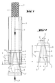
- the expansion anchor shown for example in Fig. 1 includes an anchor rod 1 a head part 2 widening in the insertion direction S.
- the head part 2 can, as shown, essentially expand conically.
- a lateral surface 11 can also be used have, which widens in the insertion direction S trumpet-shaped.
- On hers opposite end is the anchor rod 1 with a load application means 10, for example, an external thread.
- a cylindrical sleeve 3 sits axially slidably on the anchor rod 1. At its end area facing the head part 2 has the sleeve 3 separated by axial slots 5 spreading tabs 6, the extend from a plastic joint 4 to the free front end 7 of the sleeve 3.
- the plastic joint 4 is perpendicular to the axis A of the expansion anchor arranged circumferential annular groove formed in the outer surface of the sleeve 3.
- the spreading flaps 6 By the Sleeve 3 is pushed in the insertion direction S onto the head part 2 of the anchor rod 1, are the spreading flaps 6 radially.
- the spreading tabs 6 have an axial length 1 which is equal to or exceeds the axial length of the head part 2.
- each spreading tab 6 is included groove-like depressions 8 and 9 equipped, which extend from the free front end 7 of the Extend spreading flap 6 to the plastic joint 4.
- 1 and 2 are the groove-like depressions 8, 9 are provided over the entire length 1 of the spreading tabs 6 and open at the free front end 7 of each spreading flap 6; but you can also in the long sides of the spreading tabs 6 end.
- the groove-like depressions 8, 9 run preferably rectilinear and are parallel to one another in the unexpanded state Axis A of the expansion plug extending straight line G inclined. They point to plastic joint 4 a smaller distance d from the straight line G than at its Mouth a in the area of the free front end 7.
- the groove-like depressions 8, 9 can, as shown, be provided in the outside of the spreading flaps 6.
- the groove-like recesses 6 can also on the Shell surface 11 of the head part 2 facing the inside of the spreading tab 6 or on the Be attached inside and on the outside of the splicing flaps 6.
- the manufacture of the groove-like depressions 8, 9 can be cutting or non-cutting, for example by stamping or rolling.
- the non-cutting production is offered especially for expansion anchors, the sleeve of which is made from a sheet metal stamped and bent part consists.
- the angle ⁇ (FIG. 2), which the groove-like depressions 8, 9 enclose with one another, depends on the average opening angle ⁇ (FIG. 1) of the lateral surface 11 of the head part 2.
- Small opening angles ⁇ of the lateral surface 11 are small inclusion angles ⁇ assigned to the groove-like depressions 8, 9.
- the The lateral surface 11 is enclosed by the groove-like depressions 8, 9 Large angle ⁇ .
- angles ⁇ of approximately 14 ° to approximately 24 ° have proven themselves, preferably about 19 °.
- An opening angle ⁇ of the lateral surface 11 of the head part 2 of about 60 ° correspond to angles ⁇ between the groove-like depressions 8, 9 of about 22 ° to about 32 °, preferably 27 °.
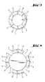
- FIG. 3 and 4 show two similar views of the expansion anchor from the view according to FIG Arrow P in Fig. 1.
- the anchor rod is in Fig. 3 omitted.
- the view of the free front end 7 of the sleeve 3 in the direction of insertion shows the spreading tabs 6 of the sleeve 3 which are separated from one another by axial slots 5
- Spreading flaps 6 are equipped with groove-like depressions 8, 9, each on open front end 7.
- t At the bottom of the groove-like depressions 8, 9 have the Spreading flap 6 a remaining material thickness t, which is about the axial extent of the groove-like depressions 8, 9 can be different.
- the remaining material thickness is t same at the mouth of the groove-like depressions 8, 9 at the free front end or less than at the plastic joint 4.
- FIG. 4 shows a view of the free front end 7 of the sleeve 3 according to FIG. 3 the head part 2 pushed on and radially flared spreading flap 6.
- Die groove-like depressions 8, 9 in the outer surface of the expansion tabs 6 act like axial ones plastic joints and allow the spreading flaps to lie flat as axial plastic joints acting groove-like depressions can Align the spreading lobe with the curvature of the lateral surface 11 of the head part 2.
- the formation of the spreading tabs according to the invention proves particularly in Undercut systems an advantage. Due to the possibility of the curvature of the spreading lobe also in the circumferential direction to the curvature of the lateral surface of the Adjusting the insertion direction expanding headboard becomes a flat system of the Spreading rag achieved. This increases the rigidity of the dowel system, which is what is particularly advantageous for self-tapping undercut systems. Because of the axial Plastic joints acting groove-like depressions will create the Spreading cloth on the ground improved and the load can be more gently in the Be initiated underground.
Landscapes
- Engineering & Computer Science (AREA)
- General Engineering & Computer Science (AREA)
- Mechanical Engineering (AREA)
- Dowels (AREA)
- Joining Of Building Structures In Genera (AREA)
Applications Claiming Priority (2)
| Application Number | Priority Date | Filing Date | Title |
|---|---|---|---|
| DE19709567 | 1997-03-08 | ||
| DE19709567A DE19709567A1 (de) | 1997-03-08 | 1997-03-08 | Spreizanker |
Publications (3)
| Publication Number | Publication Date |
|---|---|
| EP0863318A2 true EP0863318A2 (fr) | 1998-09-09 |
| EP0863318A3 EP0863318A3 (fr) | 1998-12-30 |
| EP0863318B1 EP0863318B1 (fr) | 2001-10-04 |
Family
ID=7822694
Family Applications (1)
| Application Number | Title | Priority Date | Filing Date |
|---|---|---|---|
| EP98810031A Expired - Lifetime EP0863318B1 (fr) | 1997-03-08 | 1998-01-22 | Boulon d'ancrage |
Country Status (5)
| Country | Link |
|---|---|
| US (1) | US6027292A (fr) |
| EP (1) | EP0863318B1 (fr) |
| JP (1) | JP4068712B2 (fr) |
| KR (1) | KR19980079744A (fr) |
| DE (2) | DE19709567A1 (fr) |
Cited By (2)
| Publication number | Priority date | Publication date | Assignee | Title |
|---|---|---|---|---|
| US7744320B2 (en) | 2006-06-05 | 2010-06-29 | Illinois Tool Works Inc. | Anchor bolt and annularly grooved expansion sleeve assembly exhibiting high pull-out resistance, particularly under cracked concrete test conditions |
| US7811037B2 (en) | 2006-06-05 | 2010-10-12 | Illinois Tool Works Inc. | Anchor bolt and annularly grooved expansion sleeve assembly exhibiting high pull-out resistance, particularly under cracked concrete test conditions |
Families Citing this family (14)
| Publication number | Priority date | Publication date | Assignee | Title |
|---|---|---|---|---|
| DE19819724A1 (de) * | 1998-05-02 | 1999-11-04 | Hilti Ag | Dübel |
| DE10035580B4 (de) * | 2000-07-21 | 2013-07-25 | Simpson Strong-Tie Ireland Limited | Formschlüssig setzbarer Hinterschneid-Anker |
| ATE292757T1 (de) * | 2001-03-19 | 2005-04-15 | Tai-Ping Hsu | Spreizanker |
| US7357613B2 (en) * | 2006-01-26 | 2008-04-15 | Simpson Strong -Tie Company, Inc. | Expansion anchor with crack-arresting groove |
| DE102006000486A1 (de) * | 2006-09-28 | 2008-04-10 | Hilti Ag | Ankerstab und Anordnung zum Verstärken von bestehenden Bauteilen gegen Durchstanzen mit einem solchen Ankerstab |
| US8807982B2 (en) * | 2010-04-05 | 2014-08-19 | Tindall Corporation | Expandable molding insert apparatus and method |
| FR3013085B1 (fr) * | 2013-11-13 | 2015-11-27 | Illinois Tool Works | Cheville a douille expansible et son utilisation pour la fixation d'une piece a un materiau support |
| US9581185B2 (en) | 2014-08-21 | 2017-02-28 | Precision Tower Products, Llc | Blind fastener |
| US10132344B2 (en) * | 2016-12-29 | 2018-11-20 | Kabushiki Kaisha Miyanaga | Anchor bolt |
| CN108506304A (zh) * | 2017-04-15 | 2018-09-07 | 裴志胜 | 一种带有折弯槽的高强抗拔锚固件 |
| EP3636938A1 (fr) | 2018-10-09 | 2020-04-15 | Hilti Aktiengesellschaft | Cheville à expansion comprenant des rainures vers le avant et vers l'arrière |
| US11732740B2 (en) | 2020-05-12 | 2023-08-22 | Sky Climber Fasteners LLC | Blind fastener |
| CN113585631B (zh) * | 2021-07-30 | 2024-10-29 | 哈尔滨工业大学 | 用于多束碳纤维平行拉索的连续曲锥形复合式锚具及方法 |
| US12398555B2 (en) * | 2021-12-08 | 2025-08-26 | Black & Decker Inc. | Undercut anchor |
Family Cites Families (10)
| Publication number | Priority date | Publication date | Assignee | Title |
|---|---|---|---|---|
| US3107570A (en) * | 1961-10-11 | 1963-10-22 | Us Expansion Bolt Co | Fastening device |
| US3922947A (en) * | 1973-03-06 | 1975-12-02 | Gen Cable Corp | Drop in anchor stud |
| DE3031048C2 (de) * | 1980-08-16 | 1985-02-28 | Upat Gmbh & Co, 7830 Emmendingen | Spreizanker |
| DE3120809A1 (de) * | 1981-05-25 | 1982-12-16 | Hilti AG, 9494 Schaan | Ankerbolzen mit zylindrischem bolzenkoerper |
| EP0068227B1 (fr) * | 1981-06-19 | 1986-01-29 | UPAT GMBH & CO | Boulon d'ancrage |
| CH661569A5 (en) * | 1983-08-09 | 1987-07-31 | Egli Fischer & Co | Anchor screw |
| DE3510163A1 (de) * | 1985-03-21 | 1986-09-25 | Artur Dr.H.C. 7244 Waldachtal Fischer | Spreizduebel fuer die verankerung in konisch nach innen erweitert hergestellten bohrloechern |
| DE3835300A1 (de) * | 1988-10-17 | 1990-04-19 | Hilti Ag | Spreizanker |
| US5137395A (en) * | 1989-08-02 | 1992-08-11 | Ingersoll-Rand Company | Dynamic earth anchor, and a sleeve therefor |
| CA2122945C (fr) * | 1993-05-05 | 2003-06-10 | John Christian Wilkinson | Boulon d'ancrage a coquille et a cone |
-
1997
- 1997-03-08 DE DE19709567A patent/DE19709567A1/de not_active Withdrawn
-
1998
- 1998-01-22 EP EP98810031A patent/EP0863318B1/fr not_active Expired - Lifetime
- 1998-01-22 DE DE59801603T patent/DE59801603D1/de not_active Expired - Lifetime
- 1998-02-19 KR KR1019980005174A patent/KR19980079744A/ko not_active Ceased
- 1998-02-25 US US09/030,570 patent/US6027292A/en not_active Expired - Lifetime
- 1998-03-06 JP JP05499998A patent/JP4068712B2/ja not_active Expired - Fee Related
Cited By (4)
| Publication number | Priority date | Publication date | Assignee | Title |
|---|---|---|---|---|
| US7744320B2 (en) | 2006-06-05 | 2010-06-29 | Illinois Tool Works Inc. | Anchor bolt and annularly grooved expansion sleeve assembly exhibiting high pull-out resistance, particularly under cracked concrete test conditions |
| US7811037B2 (en) | 2006-06-05 | 2010-10-12 | Illinois Tool Works Inc. | Anchor bolt and annularly grooved expansion sleeve assembly exhibiting high pull-out resistance, particularly under cracked concrete test conditions |
| US8302276B2 (en) | 2006-06-05 | 2012-11-06 | Illinois Tool Works Inc. | Anchor bolt and annularly grooved expansion sleeve assembly exhibiting high pull-out resistance, particularly under cracked concrete test conditions |
| US8491244B2 (en) | 2006-06-05 | 2013-07-23 | Illinois Tool Works Inc. | Anchor bolt and annularly grooved expansion sleeve assembly exhibiting high pull-out resistance, particularly under cracked concrete test conditions |
Also Published As
| Publication number | Publication date |
|---|---|
| EP0863318A3 (fr) | 1998-12-30 |
| JPH10259812A (ja) | 1998-09-29 |
| KR19980079744A (ko) | 1998-11-25 |
| JP4068712B2 (ja) | 2008-03-26 |
| US6027292A (en) | 2000-02-22 |
| DE59801603D1 (de) | 2001-11-08 |
| DE19709567A1 (de) | 1998-09-10 |
| EP0863318B1 (fr) | 2001-10-04 |
Similar Documents
| Publication | Publication Date | Title |
|---|---|---|
| EP0863318B1 (fr) | Boulon d'ancrage | |
| EP0308620B1 (fr) | Piston à expansion | |
| EP0308619A1 (fr) | Chéville à expansion | |
| EP0790415B1 (fr) | Cheville d'expansion | |
| CH656192A5 (de) | Spreizanker. | |
| EP0267148A1 (fr) | Cheville à expansion avec deux cônes d'écartation différents | |
| EP0818630B1 (fr) | ncre autoforeuse à contre-dépouille | |
| DE2617191A1 (de) | Spreizduebel | |
| DE3413854C2 (fr) | ||
| EP0964168B1 (fr) | Ancre à contre-dépouille | |
| EP0899468B1 (fr) | Ancre à contre-dépouille | |
| EP0225845A1 (fr) | Cheville à expansion comprenant un appendice sur l'élement extensible | |
| EP0757185B1 (fr) | Cheville à noyau d'expansion | |
| EP0926359B1 (fr) | Cheville pour trou d'ancrage à contre-dépouille | |
| EP0995913B1 (fr) | Cheville pour trou de forage à contre-dépouille | |
| EP0889250B1 (fr) | Cheville | |
| EP0290654B1 (fr) | Cheville à expansion pour l'ancrage à engagement positif dans un trou de forage | |
| DE19538898C2 (de) | Schlaganker | |
| EP0182741B1 (fr) | Cheville expansible | |
| EP0905388A1 (fr) | Boulon d'ancrage | |
| EP0421104B1 (fr) | Cheville expansible et méthode pour sa fabrication | |
| EP0892181B1 (fr) | Cheville à expansion | |
| DE102007036349A1 (de) | Montageeinheit, Befestigereinheit und Verfahren zur Herstellung einer Montageeinheit | |
| DE102020129959A1 (de) | Spreizanker und Verfahren zu seiner Verankerung | |
| EP0184988B1 (fr) | Cheville expansible à filet femelle |
Legal Events
| Date | Code | Title | Description |
|---|---|---|---|
| PUAI | Public reference made under article 153(3) epc to a published international application that has entered the european phase |
Free format text: ORIGINAL CODE: 0009012 |
|
| AK | Designated contracting states |
Kind code of ref document: A2 Designated state(s): CH DE FR GB LI |
|
| PUAL | Search report despatched |
Free format text: ORIGINAL CODE: 0009013 |
|
| AK | Designated contracting states |
Kind code of ref document: A3 Designated state(s): AT BE CH DE DK ES FI FR GB GR IE IT LI LU MC NL PT SE |
|
| 17P | Request for examination filed |
Effective date: 19990630 |
|
| AKX | Designation fees paid |
Free format text: CH DE FR GB LI |
|
| GRAG | Despatch of communication of intention to grant |
Free format text: ORIGINAL CODE: EPIDOS AGRA |
|
| GRAG | Despatch of communication of intention to grant |
Free format text: ORIGINAL CODE: EPIDOS AGRA |
|
| GRAH | Despatch of communication of intention to grant a patent |
Free format text: ORIGINAL CODE: EPIDOS IGRA |
|
| 17Q | First examination report despatched |
Effective date: 20010220 |
|
| GRAH | Despatch of communication of intention to grant a patent |
Free format text: ORIGINAL CODE: EPIDOS IGRA |
|
| GRAA | (expected) grant |
Free format text: ORIGINAL CODE: 0009210 |
|
| AK | Designated contracting states |
Kind code of ref document: B1 Designated state(s): CH DE FR GB LI |
|
| REG | Reference to a national code |
Ref country code: CH Ref legal event code: EP |
|
| REF | Corresponds to: |
Ref document number: 59801603 Country of ref document: DE Date of ref document: 20011108 |
|
| REG | Reference to a national code |
Ref country code: GB Ref legal event code: IF02 |
|
| GBT | Gb: translation of ep patent filed (gb section 77(6)(a)/1977) |
Effective date: 20011212 |
|
| ET | Fr: translation filed | ||
| PLBE | No opposition filed within time limit |
Free format text: ORIGINAL CODE: 0009261 |
|
| STAA | Information on the status of an ep patent application or granted ep patent |
Free format text: STATUS: NO OPPOSITION FILED WITHIN TIME LIMIT |
|
| 26N | No opposition filed | ||
| PGFP | Annual fee paid to national office [announced via postgrant information from national office to epo] |
Ref country code: CH Payment date: 20060127 Year of fee payment: 9 |
|
| PG25 | Lapsed in a contracting state [announced via postgrant information from national office to epo] |
Ref country code: LI Free format text: LAPSE BECAUSE OF NON-PAYMENT OF DUE FEES Effective date: 20070131 Ref country code: CH Free format text: LAPSE BECAUSE OF NON-PAYMENT OF DUE FEES Effective date: 20070131 |
|
| REG | Reference to a national code |
Ref country code: CH Ref legal event code: PL |
|
| GBPC | Gb: european patent ceased through non-payment of renewal fee |
Effective date: 20070122 |
|
| PG25 | Lapsed in a contracting state [announced via postgrant information from national office to epo] |
Ref country code: GB Free format text: LAPSE BECAUSE OF NON-PAYMENT OF DUE FEES Effective date: 20070122 |
|
| PGFP | Annual fee paid to national office [announced via postgrant information from national office to epo] |
Ref country code: GB Payment date: 20060118 Year of fee payment: 9 |
|
| REG | Reference to a national code |
Ref country code: FR Ref legal event code: PLFP Year of fee payment: 19 |
|
| PGFP | Annual fee paid to national office [announced via postgrant information from national office to epo] |
Ref country code: FR Payment date: 20151208 Year of fee payment: 19 |
|
| PGFP | Annual fee paid to national office [announced via postgrant information from national office to epo] |
Ref country code: DE Payment date: 20160119 Year of fee payment: 19 |
|
| REG | Reference to a national code |
Ref country code: DE Ref legal event code: R119 Ref document number: 59801603 Country of ref document: DE |
|
| REG | Reference to a national code |
Ref country code: FR Ref legal event code: ST Effective date: 20170929 |
|
| PG25 | Lapsed in a contracting state [announced via postgrant information from national office to epo] |
Ref country code: FR Free format text: LAPSE BECAUSE OF NON-PAYMENT OF DUE FEES Effective date: 20170131 |
|
| PG25 | Lapsed in a contracting state [announced via postgrant information from national office to epo] |
Ref country code: DE Free format text: LAPSE BECAUSE OF NON-PAYMENT OF DUE FEES Effective date: 20170801 |