EP0863350B1 - Dispositif de fixation de tuyaux - Google Patents
Dispositif de fixation de tuyaux Download PDFInfo
- Publication number
- EP0863350B1 EP0863350B1 EP97122307A EP97122307A EP0863350B1 EP 0863350 B1 EP0863350 B1 EP 0863350B1 EP 97122307 A EP97122307 A EP 97122307A EP 97122307 A EP97122307 A EP 97122307A EP 0863350 B1 EP0863350 B1 EP 0863350B1
- Authority
- EP
- European Patent Office
- Prior art keywords
- region
- latching
- arms
- central region
- designed
- Prior art date
- Legal status (The legal status is an assumption and is not a legal conclusion. Google has not performed a legal analysis and makes no representation as to the accuracy of the status listed.)
- Expired - Lifetime
Links
- 238000007789 sealing Methods 0.000 claims description 28
- 238000004804 winding Methods 0.000 claims description 23
- 239000000463 material Substances 0.000 claims description 5
- 210000001331 nose Anatomy 0.000 claims 3
- 230000015572 biosynthetic process Effects 0.000 claims 1
- 238000005755 formation reaction Methods 0.000 claims 1
- 238000001746 injection moulding Methods 0.000 claims 1
- 230000007480 spreading Effects 0.000 description 3
- 230000003993 interaction Effects 0.000 description 2
- 238000000034 method Methods 0.000 description 2
- 230000008569 process Effects 0.000 description 2
- 230000009471 action Effects 0.000 description 1
- 239000000853 adhesive Substances 0.000 description 1
- 230000008859 change Effects 0.000 description 1
- 210000000078 claw Anatomy 0.000 description 1
- 238000010276 construction Methods 0.000 description 1
- 238000011161 development Methods 0.000 description 1
- 230000018109 developmental process Effects 0.000 description 1
- 238000005507 spraying Methods 0.000 description 1
Images
Classifications
-
- B—PERFORMING OPERATIONS; TRANSPORTING
- B60—VEHICLES IN GENERAL
- B60R—VEHICLES, VEHICLE FITTINGS, OR VEHICLE PARTS, NOT OTHERWISE PROVIDED FOR
- B60R16/00—Electric or fluid circuits specially adapted for vehicles and not otherwise provided for; Arrangement of elements of electric or fluid circuits specially adapted for vehicles and not otherwise provided for
- B60R16/02—Electric or fluid circuits specially adapted for vehicles and not otherwise provided for; Arrangement of elements of electric or fluid circuits specially adapted for vehicles and not otherwise provided for electric constitutive elements
- B60R16/0207—Wire harnesses
- B60R16/0215—Protecting, fastening and routing means therefor
-
- F—MECHANICAL ENGINEERING; LIGHTING; HEATING; WEAPONS; BLASTING
- F16—ENGINEERING ELEMENTS AND UNITS; GENERAL MEASURES FOR PRODUCING AND MAINTAINING EFFECTIVE FUNCTIONING OF MACHINES OR INSTALLATIONS; THERMAL INSULATION IN GENERAL
- F16L—PIPES; JOINTS OR FITTINGS FOR PIPES; SUPPORTS FOR PIPES, CABLES OR PROTECTIVE TUBING; MEANS FOR THERMAL INSULATION IN GENERAL
- F16L3/00—Supports for pipes, cables or protective tubing, e.g. hangers, holders, clamps, cleats, clips, brackets
- F16L3/24—Supports for pipes, cables or protective tubing, e.g. hangers, holders, clamps, cleats, clips, brackets with special member for attachment to profiled girders
- F16L3/243—Supports for pipes, cables or protective tubing, e.g. hangers, holders, clamps, cleats, clips, brackets with special member for attachment to profiled girders the special member being inserted in the profiled girder
-
- H—ELECTRICITY
- H02—GENERATION; CONVERSION OR DISTRIBUTION OF ELECTRIC POWER
- H02G—INSTALLATION OF ELECTRIC CABLES OR LINES, OR OF COMBINED OPTICAL AND ELECTRIC CABLES OR LINES
- H02G3/00—Installations of electric cables or lines or protective tubing therefor in or on buildings, equivalent structures or vehicles
- H02G3/30—Installations of cables or lines on walls, floors or ceilings
- H02G3/32—Installations of cables or lines on walls, floors or ceilings using mounting clamps
Definitions
- the invention relates to a device for holding of pipes, cables or tubular objects with one with a support area to be connected to and above arranged, protruding on both sides beyond the holding area Storage area, according to the preamble of claim 1.
- Such a device is already state of the art known (FR-PS 2 717 554), in which the storage area is bowl-shaped is trained. In the middle of the bowl there are two clip-like elements in which one to be fastened Tube can be clipped. Alternatively there is also Possibility through self-adhesive band-shaped fastening elements to loop several pipes and this - on the bowl-shaped Fasten storage area.
- the disadvantage is this well-known construction that spans a longer period Period of time can release these ribbon-shaped fasteners so that the function of the holding safety is no longer guaranteed is.
- a device for holding pipes in which the storage area is relatively short and has a continuous opening on the underside through which a band-shaped fastening element extends through (CA-PS 695 251).
- the pipes to be held are only relative over one small storage area.
- Another state of the art is a device which two half-shell-like hinges There are elements that encompass the pipes to be held (GB 214 900 A).
- the Storage area each has a winding zone on its end face, which consists of at least two resilient arms extending in the longitudinal direction of the storage area consists. Through this winding zone created a resilient area that prevents themselves band-shaped fasteners that this winding zone enclose, loosen.
- the pipes to be held or Cables are thus flawless and reliable on the inventive Device attached.
- the winding zone can each consist of three, through two slots separate, resilient arms exist.
- the resilient arms - whether two or more - can be on the underside with at least one latch, preferably with several, equipped with spaced latches his.
- These locking lugs can have a sawtooth shape. In order to experiences the band-shaped fastener when looping the winding zone an additional security, especially against Move. There is also the option at the end of the To use a kind of hook-shaped locking lug to change the to achieve the same aforementioned effect.
- the winding zone each go into an enlarged, central area, which is connected to the holding area.
- This middle one The area can be tapered with the two winding zones be connected, the tapered part of the middle Area can be provided with side recesses. This creates a kind of bridge with high material savings, however great strength.
- the middle area can be above the holding area a continuous, transverse to the pipe longitudinal direction
- the top of the Wrapping zones and / or the central area one or more Locking cams are provided, which are in the middle or on the side and / or at the same or different distance from each other on the top of the winding zones and / or the central area are arranged.
- These randomly designed locking cams press themselves into the scope of the pipe to be held or pipes to be held and thus result in interaction with the band-shaped fastening element wrapping around the winding zones a very good holder for the to be fastened Elements.
- a circumferential sealing lip can be arranged, for example on the front with a made of a softer material Sealing ring is provided. This results in a good sealing effect against a carrier opening, the sealing ring for example polygonal or round in cross-section is.
- the holding area can be a clip, a profile or a threaded bolt, as part of a bayonet lock or as a sliding bearing be trained. If the holding area is designed as a clip, can be round, oval or rectangular in cross-section be formed depending on the shape of an existing carrier opening.
- the clip can be distributed over the circumference at least two resilient, have locking arms directed against the sealing lip, which, for example, has one or more end faces Gradations are provided. These resilient locking arms with their Gradations reach behind the relevant beam opening and keep the device according to the invention properly.
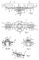
- the device for holding shown in FIGS. 1 to 4 of pipes essentially consists of one with one not holding area 1 and one arranged above, on both sides over the holding area 1 protruding storage area 2.
- the storage area 2 has according to FIG. 2 in each case on its end face S a winding zone 10, 10 '.
- the winding zones 10 and 10 ' are each in the illustrated embodiment three, through two slots 11 and 12 or 11 'and 12' from each other separate, resilient arms 7, 8, 9 or 7 ', 8', 9 ' educated.
- Fasteners 41 and 41 ' which e.g. one to be held Loop around tube 42 so that an unintentional Solve also over a longer period and / or under the influence of heat is properly avoided.
- the resilient arms 7, 8, 9 or 7', 8 ', 9' be provided on the underside with locking lugs 20 and 20 '.
- This Lugs are, for example, sawtooth-shaped. she claw into the band-shaped fastener in question 41 or 41 'and secure its location after the Wrapping one or more tubes 42 to be held.
- locking cams 40 are provided on the top of the storage area be, for example, at a uniform distance according to Fig. 1 and 2 lie. These latching cams can be centered according to FIG. 2 be arranged at the top of the storage area and up extend to the front of the middle arms 8 and 8 '.
- the shape of these locking cams 40 is arbitrary. However, it has to be guaranteed that when looping the to be held Pipes 42 with the band-shaped fastening elements 41 or 41 'the locking cams 40 so the outer circumference of the to be held Pipes act as an additional locking device given is.
- This middle area 30 can be tapered parts 31 and 32 with the two Be winding zones 10 and 10 'connected.
- This tapered Parts can according to FIGS. 1 and 4 with side recesses 33 and 35, so that a kind of bridge with high strength, but good material savings.
- FIG. 4A shows that the middle area 30 above the holding area 1 a continuous, transverse to the pipe longitudinal direction Has recess 36.
- This recess 36 can with be provided with a locking element 37. So there is the possibility of a cable tape, not shown, through to pass the recess and to wrap other Use tubes, this cable tie with the locking element 37 safe to move on the invention Device 1 is attached.
- the holding area 1 shown in FIGS. 1, 3 and 4 can as a clip, as a profile or threaded bolt, as part of one Bayonet lock or be designed as a sliding bearing.
- the holding area 1 is a clip 5 designed.
- This clip 5 can be round, oval in cross section or be rectangular. He points out the scope distributed according to FIGS. 1 and 3 at least two locking arms 18 and 19 on, one being resilient and the other rigid can be or there are two resilient locking lugs.
- sealing lip 22 can in the embodiment 1 to 4 formed in one piece his.
- the locking arms 18 and directed towards the sealing lip 22 or 22 ' 19 or 18 'and 19' can with several gradations 21 Fig. 3 or with a single gradation 21 'in the embodiment 4 A may be provided.
- the sealing ring 23 can with the help of the known two-component spraying process connected to the sealing lip 22 ' his.
- Sealing ring 23 in a mechanical manner with the sealing lip 22 ' connect.
- the Pin-like holding elements can also be provided, which after passing through the sealing lip 22 'in Store cutouts.
Landscapes
- Engineering & Computer Science (AREA)
- General Engineering & Computer Science (AREA)
- Mechanical Engineering (AREA)
- Architecture (AREA)
- Civil Engineering (AREA)
- Structural Engineering (AREA)
- Clamps And Clips (AREA)
- Supports For Pipes And Cables (AREA)
- Mutual Connection Of Rods And Tubes (AREA)
Claims (23)
- Dispositif pour la fixation de tubes, de câbles ou d'objets de forme tubulaire comportant une partie de retenue (1; 1') devant être raccordée à un support, et une partie de support (2) disposée au-dessus de la partie de retenue et fait saillie des deux côtés au-delà de la partie de retenue (1; 1') et à laquelle au moins un tube doit être fixé à l'aide d'au moins un élément de fixation en forme de bande (41; 41'), caractérisé en ce
que la partie de support (2) possède respectivement sur sa face frontale (S), une zone de bobinage (10, 10'), qui est constituée par au moins deux bras élastiques (7, 8, 9, 7', 8', 9') qui s'étendent dans la direction longitudinale de la partie de support (2). - Dispositif selon la revendication 1, caractérisé en ce
que la zone de bobinage (10; 10') est constituée respectivement de trois bras élastiques (7, 8, 9; 7', 8', 9'), qui sont séparés les uns des autres par deux fentes (11, 12; 11', 12'). - Dispositif selon la revendication 2, caractérisé en ce
que les deux bras extérieurs (7, 9; 7', 9') sont agencés extérieurement de manière à converger selon une forme conique (15, 16; 15', 16') en direction de la partie de retenue (1; 1'). - Dispositif selon une ou plusieurs des revendications précédentes, caractérisé en ce
que les bras élastiques (7, 8, 9; 7', 8', 9') sont pourvus, au niveau de leur face inférieure, d'au moins un bec d'encliquetage (20; 20'). - Dispositif selon la revendication 4, caractérisé en ce par
plusieurs becs d'encliquetage (20; 20') situés à distance les uns des autres. - Dispositif selon la revendication 4 ou 5, caractérisé en ce
que les becs d'encliquetage (20; 20') possèdent une forme en dents de scie. - Dispositif selon une ou plusieurs des revendications précédentes, caractérisé en ce
que la zone de bobinage (10; 10') se prolonge respectivement par une partie médiane agrandie (30), qui est reliée à la partie de retenue (1; 1'). - Dispositif selon la revendication 7, caractérisé en ce
que la partie médiane (30) est reliée, en convergeant avec une forme conique, aux deux zones de bobinage (10; 10'). - Dispositif selon les revendications 7 et 8, caractérisé en ce
que la partie (31, 32), qui converge avec une forme conique, est pourvue d'évidements latéraux (33, 34). - Dispositif selon les revendications 7 à 9, caractérisé en ce
que la partie médiane (30) possède, au-dessus de la partie de retenue (1; 1'), un évidement continu (36), qui s'étend transversalement par rapport à la direction longitudinale de la partie de support. - Dispositif selon la revendication 10, caractérisé en ce
que l'évidement (36) est pourvu d'un élément de verrouillage (37). - Dispositif selon une ou plusieurs des revendications précédentes, caractérisé en ce
qu'au moins un téton d'encliquetage (40) est prévu sur la face supérieure des zones de bobinage (10; 10') et/ou de la partie médiane (3). - Dispositif selon la revendication 13, caractérisé par
plusieurs tétons d'encliquetage (40). - Dispositif selon la revendication 13, caractérisé en ce
que les tétons d'encliquetage (40) sont situés à une même distance les uns des autres sur la face supérieure des zones de bobinage (10; 10') et/ou de la partie médiane (30). - Dispositif selon la revendication 14, caractérisé en ce
que les tétons d'encliquetage (40) sont disposés au centre de la face supérieure. - Dispositif selon une ou plusieurs des revendications précédentes, caractérisé en ce
qu'une lèvre périphérique d'étanchéité (22; 22') est disposée entre la partie de retenue (1) et la partie médiane (30). - Dispositif selon la revendication 16, caractérisé en ce
que la lèvre périphérique d'étanchéité (22') est pourvue frontalement d'une bague d'étanchéité (23) réalisée en un matériau plus mou. - Dispositif selon la revendication 17, caractérisé en ce
que la bague d'étanchéité (23) possède une section transversale de forme polygonale ou circulaire. - Dispositif selon la revendication 16 ou 17, caractérisé en ce
que la bague d'étanchéité (23) est reliée selon le procédé de moulage par injection à deux constituants ou bien mécaniquement à la lèvre périphérique d'étanchéité (22'). - Dispositif selon une ou plusieurs des revendications précédentes, caractérisé en ce
que la partie de retenue (1) est agencée sous la forme d'une pince (5), sous la forme d'un goujon profilée ou d'un boulon fileté, en tant que partie d'un dispositif de fermeture à baïonnette ou en tant que support coulissant. - Dispositif selon la revendication 20, caractérisé en ce
que la pince (5) agencée en tant que partie de retenue possède une section transversale circulaire, ovale ou rectangulaire. - Dispositif selon la revendication 21, caractérisé en ce
que la pince (5) comporte au moins deux bras élastiques d'encliquetage (18, 19; 18', 19'), qui sont répartis sur la périphérie et sont dirigés vers la lèvre d'étanchéité (22; 22'). - Dispositif selon la revendication 22, caractérisé en ce que
que les bras d'encliquetage (18, 19; 18', 19') sont pourvus frontalement d' une ou de plusieurs parties étagées (21, 21').
Priority Applications (1)
| Application Number | Priority Date | Filing Date | Title |
|---|---|---|---|
| DE29724330U DE29724330U1 (de) | 1997-02-07 | 1997-12-17 | Vorrichtung zum Haltern von Rohren |
Applications Claiming Priority (2)
| Application Number | Priority Date | Filing Date | Title |
|---|---|---|---|
| DE19704674 | 1997-02-07 | ||
| DE19704674A DE19704674A1 (de) | 1997-02-07 | 1997-02-07 | Vorrichtung zum Haltern von Rohren |
Publications (3)
| Publication Number | Publication Date |
|---|---|
| EP0863350A2 EP0863350A2 (fr) | 1998-09-09 |
| EP0863350A3 EP0863350A3 (fr) | 1998-11-04 |
| EP0863350B1 true EP0863350B1 (fr) | 2001-05-23 |
Family
ID=7819607
Family Applications (1)
| Application Number | Title | Priority Date | Filing Date |
|---|---|---|---|
| EP97122307A Expired - Lifetime EP0863350B1 (fr) | 1997-02-07 | 1997-12-17 | Dispositif de fixation de tuyaux |
Country Status (4)
| Country | Link |
|---|---|
| US (1) | US6076781A (fr) |
| EP (1) | EP0863350B1 (fr) |
| DE (2) | DE19704674A1 (fr) |
| ES (1) | ES2157044T3 (fr) |
Families Citing this family (40)
| Publication number | Priority date | Publication date | Assignee | Title |
|---|---|---|---|---|
| FR2777061B1 (fr) * | 1998-04-03 | 2000-06-16 | Sofanou Sa | Piece d'installation d'elements longilignes contre une paroi et outil de mise en place de ladite piece |
| DE19843633C2 (de) * | 1998-09-23 | 2002-10-31 | Trw Automotive Electron & Comp | Vorrichtung aus Kunststoff zum Haltern von Rohren, Kabeln oder rohrförmigen Gegenständen |
| DE60113528T2 (de) | 2001-07-13 | 2006-06-29 | I.T.W. España, S.A., Las Franquesas del Valles | Verstellbare Stütze zur Befestigung von Kabelbündeln und dergleichen |
| DE10141542B4 (de) * | 2001-08-24 | 2008-04-30 | Audi Ag | Einrichtung zum Festlegen von Gegenständen an einem Widerlager |
| DE10256144A1 (de) * | 2002-11-29 | 2004-06-17 | Newfrey Llc, Newark | Befestigungsvorrichtung für einen länglichen Gegenstand, insbesondere Kabelbaum |
| US20060051181A1 (en) * | 2004-09-08 | 2006-03-09 | Winton George R Iii | Universal clinch base |
| US7455192B2 (en) | 2004-11-03 | 2008-11-25 | Illinois Tool Works Inc. | Overmolded adhesive hole plug |
| KR100676324B1 (ko) * | 2005-03-15 | 2007-01-30 | 삼성전자주식회사 | 디스플레이장치 |
| ES2264635B1 (es) * | 2005-04-15 | 2007-12-01 | I.T.W. España, S.A. | Dispositivo para fijar elementos alargados flexibles, tal y como tubos flexibles o mazos de cables, a una estructura. |
| US20070034750A1 (en) * | 2005-08-10 | 2007-02-15 | Kns Associates, Inc. | Tubing mounting clip |
| DE202005017160U1 (de) * | 2005-11-03 | 2007-04-05 | Hellermann Tyton Gmbh | Befestigungsschiene für einen langgestreckten Gegenstand |
| JP2007174887A (ja) | 2005-11-24 | 2007-07-05 | Daiwa Kasei Ind Co Ltd | 留め具 |
| US7913957B2 (en) * | 2006-05-08 | 2011-03-29 | Panduit Corp. | Mounting device and apparatus for use with studs comprising T-shaped channels |
| US20070272807A1 (en) * | 2006-05-18 | 2007-11-29 | Hellermanntyton Co., Ltd. | Part mounting clamp |
| WO2007134634A1 (fr) * | 2006-05-18 | 2007-11-29 | Auto Kabel Managementgesellschaft Mbh | Profilé électrique pour traversées de câbles |
| US7793895B2 (en) * | 2006-06-13 | 2010-09-14 | Avery Dennison Corporation | Cable tie for an automotive valve cover |
| FR2905039B1 (fr) * | 2006-08-17 | 2008-12-19 | Airbus France Sas | Support pour fixer des cables electriques sur une structure |
| DE202006015674U1 (de) * | 2006-10-12 | 2007-01-18 | Trw Automotive Electronics & Components Gmbh & Co. Kg | Befestigungsvorrichtung für eine Leitung |
| CN101478126B (zh) * | 2009-01-22 | 2011-07-06 | 重庆隆鑫机车有限公司 | 摩托车布线定位卡 |
| US8221042B2 (en) * | 2009-03-05 | 2012-07-17 | Ford Global Technologies, Llc | Anti-rotation fastener for an automotive component and panel |
| US20110147541A1 (en) * | 2009-12-23 | 2011-06-23 | Caterpillar Inc. | Cable strap locating device for a wire harness and a wire harness assembly using the same |
| DE102010005300B4 (de) * | 2010-01-21 | 2014-02-13 | Bayerische Motoren Werke Aktiengesellschaft | Vorrichtung zum Befestigen eines länglichen Gegenstandes an einer Fläche |
| JP5735781B2 (ja) * | 2010-11-24 | 2015-06-17 | 矢崎総業株式会社 | ワイヤハーネス用クランプ |
| DE102012111886B3 (de) * | 2012-12-06 | 2013-09-19 | Trw Automotive Electronics & Components Gmbh | Befestigungsclip und Befestigungsbaugruppe |
| USD698633S1 (en) | 2013-03-08 | 2014-02-04 | Hellermanntyton Corporation | Offset cable tie |
| USD723361S1 (en) | 2013-03-08 | 2015-03-03 | Hellermanntyton Corporation | Offset cable tie |
| USD741691S1 (en) | 2013-03-08 | 2015-10-27 | Hellermanntyton Corporation | Offset cable tie |
| US9162550B2 (en) * | 2013-10-08 | 2015-10-20 | Denso International America, Inc. | Wire harness mounting assembly |
| JP5999072B2 (ja) * | 2013-11-15 | 2016-09-28 | 住友電装株式会社 | ワイヤーハーネス、電線固定部品及びワイヤーハーネスの製造方法 |
| JP2015097439A (ja) * | 2013-11-15 | 2015-05-21 | 住友電装株式会社 | ワイヤーハーネス及び電線固定部品 |
| JP2016077048A (ja) * | 2014-10-03 | 2016-05-12 | 住友電装株式会社 | バンドクリップ |
| KR101584921B1 (ko) * | 2014-12-26 | 2016-01-14 | 현대다이모스(주) | 케이블 홀더 |
| GB2537901A (en) * | 2015-04-30 | 2016-11-02 | Hellermann Tyton Ltd | A Cable Support |
| BR202015013915Y1 (pt) * | 2015-06-12 | 2020-04-14 | Frontec Ind De Componentes De Fixacao Ltda | disposição aplicada em clipe cruzetado para abraçadeira |
| DE102015214109B4 (de) * | 2015-07-27 | 2024-10-10 | Magna Car Top Systems Gmbh | Befestigung mit stirnseitiger Leitungsführung |
| CN105351631A (zh) * | 2015-11-12 | 2016-02-24 | 安徽江淮汽车股份有限公司 | 一种钣金卡总成 |
| JP6934924B2 (ja) * | 2018-12-21 | 2021-09-15 | 大和化成工業株式会社 | クランプ |
| US11060544B2 (en) * | 2018-12-21 | 2021-07-13 | Daiwa Kasei Kogyo Kabushiki Kaisha | Fasteners |
| US11677222B1 (en) | 2021-12-28 | 2023-06-13 | Panduit Corp. | Winged cable mount |
| DE102022110738B3 (de) | 2022-05-02 | 2023-09-21 | Lisa Dräxlmaier GmbH | Verfahren zum automatisierten anwickeln eines anwickelteils an ein werkstück und wickelautomat |
Family Cites Families (12)
| Publication number | Priority date | Publication date | Assignee | Title |
|---|---|---|---|---|
| JPH0322570Y2 (fr) * | 1987-02-17 | 1991-05-16 | ||
| US4870722A (en) * | 1987-12-15 | 1989-10-03 | Northrop Corporation | Cable clamp strip |
| FR2648208B1 (fr) * | 1989-06-13 | 1991-11-22 | Itw De France | Pied d'encliquetage |
| US4974798A (en) * | 1989-12-18 | 1990-12-04 | Chrysler Corporation | Vehicle wiring harness cable mounting assembly structure |
| US5012995A (en) * | 1990-03-16 | 1991-05-07 | General Motors Corporation | Adjustable wiring harness clip |
| US5106040A (en) * | 1991-01-02 | 1992-04-21 | Yazaki Eds Engineering, Inc. | Steering column wire protector |
| US5505411A (en) * | 1992-10-29 | 1996-04-09 | Tyton Corporation | Harness fixing device |
| US5368261A (en) * | 1992-12-17 | 1994-11-29 | Panduit Corp. | Cable mount and fixture |
| FR2717554B1 (fr) * | 1994-03-15 | 1996-04-12 | Sylea | Ensemble pour déterminer l'écartement d'organes de fixation de câblages électriques. |
| JP2989530B2 (ja) * | 1995-10-27 | 1999-12-13 | 矢崎総業株式会社 | クリップ |
| DE19607205A1 (de) * | 1996-02-26 | 1997-09-04 | United Carr Gmbh Trw | Befestigungselement auf Kunststoff |
| US5921510A (en) * | 1996-11-21 | 1999-07-13 | Avery Dennison Corp. | Cable tie with christmas tree fastener |
-
1997
- 1997-02-07 DE DE19704674A patent/DE19704674A1/de not_active Withdrawn
- 1997-12-17 ES ES97122307T patent/ES2157044T3/es not_active Expired - Lifetime
- 1997-12-17 DE DE59703595T patent/DE59703595D1/de not_active Expired - Lifetime
- 1997-12-17 EP EP97122307A patent/EP0863350B1/fr not_active Expired - Lifetime
-
1998
- 1998-01-30 US US09/016,067 patent/US6076781A/en not_active Expired - Fee Related
Also Published As
| Publication number | Publication date |
|---|---|
| ES2157044T3 (es) | 2001-08-01 |
| DE19704674A1 (de) | 1998-08-13 |
| US6076781A (en) | 2000-06-20 |
| EP0863350A3 (fr) | 1998-11-04 |
| DE59703595D1 (de) | 2001-06-28 |
| EP0863350A2 (fr) | 1998-09-09 |
Similar Documents
| Publication | Publication Date | Title |
|---|---|---|
| EP0863350B1 (fr) | Dispositif de fixation de tuyaux | |
| EP0421055B1 (fr) | Elément en bande pour emballage et fixation d'objets | |
| DE69329562T2 (de) | Vorrichtung zum Befestigen einer Kabelhalterung | |
| DE69605251T2 (de) | Vorrichtung zum Verbinden eines Bolzens | |
| DE69936823T2 (de) | Kunststoff- Kabelhalterung für Fahrzeuge | |
| EP0483636B1 (fr) | Elément de retenue en matière plastique | |
| DE2813484A1 (de) | Kabelband | |
| DE3115060A1 (de) | Halter zur befestigung elektrischer leiter oder rohre auf einer unterlage | |
| WO1998007996A1 (fr) | Support de conduits pourvu d'une zone de logement permettant sa fixation d'un cote ou de l'autre sur une tige filetee | |
| DE2847505C2 (de) | Verstellbare Klemmvorrichtung zur Befestigung von länglichen Gegenständen an einer Halterung | |
| DE8809756U1 (de) | Verbindungselement | |
| DE1903372C3 (de) | Halteschelle für Rohre, Kabel und dergl | |
| EP1447576A1 (fr) | Ecrou en plastique pour une unité de construction montrant une percée | |
| EP0726415A1 (fr) | Elément de fixation | |
| EP1013978B1 (fr) | Dispositif de fixation en matière plastique | |
| DE7012495U (de) | Schelle zum befestigen mindestens eines langgestreckten gegenstandes. | |
| DE2744036A1 (de) | Befestigungsvorrichtung, insbesondere zur befestigung von dachplatten o.dgl. mit isolierender zwischenlage auf gebaeudeteilen | |
| DE69001764T2 (de) | Befestigungsvorrichtung. | |
| EP0261215A1 (fr) | Mousqueton, en particulier pour alpinistes | |
| DE2325233A1 (de) | Klammer | |
| DE202020101103U1 (de) | Rohrschelle sowie Baukasten für ihre Erstellung | |
| EP0803429A2 (fr) | Dispositif de fixation d'un garde-boue de bicyclette | |
| DE3047462C2 (de) | Auf einen Tragbolzen aufsetzbares Befestigungselement | |
| DE3013750A1 (de) | Vorrichtung | |
| DE3941095C1 (en) | Cable channel or tray support - has coupling element operable from above in form of self-tapping screw fitting selectable slots |
Legal Events
| Date | Code | Title | Description |
|---|---|---|---|
| PUAI | Public reference made under article 153(3) epc to a published international application that has entered the european phase |
Free format text: ORIGINAL CODE: 0009012 |
|
| AK | Designated contracting states |
Kind code of ref document: A2 Designated state(s): DE ES FR GB |
|
| AX | Request for extension of the european patent |
Free format text: AL;LT;LV;MK;RO;SI |
|
| PUAL | Search report despatched |
Free format text: ORIGINAL CODE: 0009013 |
|
| RTI1 | Title (correction) | ||
| 17P | Request for examination filed |
Effective date: 19980903 |
|
| AK | Designated contracting states |
Kind code of ref document: A3 Designated state(s): AT BE CH DE DK ES FI FR GB GR IE IT LI LU MC NL PT SE |
|
| AX | Request for extension of the european patent |
Free format text: AL;LT;LV;MK;RO;SI |
|
| RTI1 | Title (correction) | ||
| AKX | Designation fees paid |
Free format text: DE ES FR GB |
|
| 17Q | First examination report despatched |
Effective date: 19990820 |
|
| RAP1 | Party data changed (applicant data changed or rights of an application transferred) |
Owner name: TRW AUTOMOTIVE ELECTRONICS & COMPONENTS GMBH & CO. |
|
| GRAG | Despatch of communication of intention to grant |
Free format text: ORIGINAL CODE: EPIDOS AGRA |
|
| GRAG | Despatch of communication of intention to grant |
Free format text: ORIGINAL CODE: EPIDOS AGRA |
|
| RIC1 | Information provided on ipc code assigned before grant |
Free format text: 7F 16L 3/23 A, 7H 02G 3/30 B |
|
| RIC1 | Information provided on ipc code assigned before grant |
Free format text: 7F 16L 3/23 A, 7H 02G 3/30 B |
|
| GRAG | Despatch of communication of intention to grant |
Free format text: ORIGINAL CODE: EPIDOS AGRA |
|
| GRAH | Despatch of communication of intention to grant a patent |
Free format text: ORIGINAL CODE: EPIDOS IGRA |
|
| GRAH | Despatch of communication of intention to grant a patent |
Free format text: ORIGINAL CODE: EPIDOS IGRA |
|
| GRAA | (expected) grant |
Free format text: ORIGINAL CODE: 0009210 |
|
| AK | Designated contracting states |
Kind code of ref document: B1 Designated state(s): DE ES FR GB |
|
| REF | Corresponds to: |
Ref document number: 59703595 Country of ref document: DE Date of ref document: 20010628 |
|
| REG | Reference to a national code |
Ref country code: ES Ref legal event code: FG2A Ref document number: 2157044 Country of ref document: ES Kind code of ref document: T3 |
|
| GBT | Gb: translation of ep patent filed (gb section 77(6)(a)/1977) |
Effective date: 20010824 |
|
| ET | Fr: translation filed | ||
| REG | Reference to a national code |
Ref country code: GB Ref legal event code: IF02 |
|
| PLBE | No opposition filed within time limit |
Free format text: ORIGINAL CODE: 0009261 |
|
| STAA | Information on the status of an ep patent application or granted ep patent |
Free format text: STATUS: NO OPPOSITION FILED WITHIN TIME LIMIT |
|
| 26N | No opposition filed | ||
| PGFP | Annual fee paid to national office [announced via postgrant information from national office to epo] |
Ref country code: GB Payment date: 20141229 Year of fee payment: 18 Ref country code: ES Payment date: 20141226 Year of fee payment: 18 |
|
| REG | Reference to a national code |
Ref country code: FR Ref legal event code: PLFP Year of fee payment: 19 |
|
| GBPC | Gb: european patent ceased through non-payment of renewal fee |
Effective date: 20151217 |
|
| PG25 | Lapsed in a contracting state [announced via postgrant information from national office to epo] |
Ref country code: GB Free format text: LAPSE BECAUSE OF NON-PAYMENT OF DUE FEES Effective date: 20151217 |
|
| REG | Reference to a national code |
Ref country code: FR Ref legal event code: PLFP Year of fee payment: 20 |
|
| REG | Reference to a national code |
Ref country code: ES Ref legal event code: FD2A Effective date: 20170126 |
|
| PG25 | Lapsed in a contracting state [announced via postgrant information from national office to epo] |
Ref country code: ES Free format text: LAPSE BECAUSE OF NON-PAYMENT OF DUE FEES Effective date: 20151218 |
|
| PGFP | Annual fee paid to national office [announced via postgrant information from national office to epo] |
Ref country code: FR Payment date: 20161227 Year of fee payment: 20 |
|
| PGFP | Annual fee paid to national office [announced via postgrant information from national office to epo] |
Ref country code: DE Payment date: 20161229 Year of fee payment: 20 |
|
| REG | Reference to a national code |
Ref country code: DE Ref legal event code: R082 Ref document number: 59703595 Country of ref document: DE Representative=s name: HAUCK PATENTANWALTSPARTNERSCHAFT MBB, DE Ref country code: DE Ref legal event code: R081 Ref document number: 59703595 Country of ref document: DE Owner name: ILLINOIS TOOL WORKS INC. (N.D.GES.D. STAATES D, US Free format text: FORMER OWNER: TRW AUTOMOTIVE ELECTRONICS & COMPONENTS GMBH & CO. KG, 78315 RADOLFZELL, DE |
|
| REG | Reference to a national code |
Ref country code: FR Ref legal event code: TP Owner name: ITW FASTENER PRODUCTS GMBH, DE Effective date: 20171002 |
|
| REG | Reference to a national code |
Ref country code: DE Ref legal event code: R071 Ref document number: 59703595 Country of ref document: DE |