EP0863373A2 - Congélateur cryogénique à courant croisé et à plusieurs étages et procédé d'utlilisation - Google Patents
Congélateur cryogénique à courant croisé et à plusieurs étages et procédé d'utlilisation Download PDFInfo
- Publication number
- EP0863373A2 EP0863373A2 EP98400459A EP98400459A EP0863373A2 EP 0863373 A2 EP0863373 A2 EP 0863373A2 EP 98400459 A EP98400459 A EP 98400459A EP 98400459 A EP98400459 A EP 98400459A EP 0863373 A2 EP0863373 A2 EP 0863373A2
- Authority
- EP
- European Patent Office
- Prior art keywords
- product
- freezing chamber
- blowers
- chamber
- pieces
- Prior art date
- Legal status (The legal status is an assumption and is not a legal conclusion. Google has not performed a legal analysis and makes no representation as to the accuracy of the status listed.)
- Withdrawn
Links
- 238000000034 method Methods 0.000 title claims abstract description 19
- 238000007710 freezing Methods 0.000 claims abstract description 140
- 230000008014 freezing Effects 0.000 claims abstract description 140
- 239000007788 liquid Substances 0.000 claims abstract description 75
- 238000001816 cooling Methods 0.000 claims description 15
- 230000003134 recirculating effect Effects 0.000 claims description 5
- 230000008016 vaporization Effects 0.000 claims description 5
- 238000009834 vaporization Methods 0.000 claims description 4
- 238000005507 spraying Methods 0.000 claims description 3
- 230000005484 gravity Effects 0.000 claims description 2
- 238000005057 refrigeration Methods 0.000 claims description 2
- 238000013019 agitation Methods 0.000 claims 1
- 239000011148 porous material Substances 0.000 claims 1
- 235000013305 food Nutrition 0.000 abstract description 30
- 230000008569 process Effects 0.000 abstract description 5
- 239000007921 spray Substances 0.000 abstract description 4
- 238000010924 continuous production Methods 0.000 abstract 1
- 239000007789 gas Substances 0.000 description 38
- IJGRMHOSHXDMSA-UHFFFAOYSA-N Atomic nitrogen Chemical compound N#N IJGRMHOSHXDMSA-UHFFFAOYSA-N 0.000 description 30
- CURLTUGMZLYLDI-UHFFFAOYSA-N Carbon dioxide Chemical compound O=C=O CURLTUGMZLYLDI-UHFFFAOYSA-N 0.000 description 29
- 229910002092 carbon dioxide Inorganic materials 0.000 description 20
- 229910052757 nitrogen Inorganic materials 0.000 description 15
- 239000002245 particle Substances 0.000 description 9
- 239000001569 carbon dioxide Substances 0.000 description 7
- 238000007654 immersion Methods 0.000 description 6
- 241000238557 Decapoda Species 0.000 description 5
- 238000004519 manufacturing process Methods 0.000 description 5
- QGZKDVFQNNGYKY-UHFFFAOYSA-N Ammonia Chemical compound N QGZKDVFQNNGYKY-UHFFFAOYSA-N 0.000 description 4
- XKRFYHLGVUSROY-UHFFFAOYSA-N Argon Chemical compound [Ar] XKRFYHLGVUSROY-UHFFFAOYSA-N 0.000 description 4
- 230000008901 benefit Effects 0.000 description 4
- 238000009434 installation Methods 0.000 description 4
- 239000007787 solid Substances 0.000 description 4
- 238000012546 transfer Methods 0.000 description 4
- 238000002347 injection Methods 0.000 description 3
- 239000007924 injection Substances 0.000 description 3
- 230000009471 action Effects 0.000 description 2
- 229910021529 ammonia Inorganic materials 0.000 description 2
- 229910052786 argon Inorganic materials 0.000 description 2
- 235000011089 carbon dioxide Nutrition 0.000 description 2
- 230000007423 decrease Effects 0.000 description 2
- 230000003247 decreasing effect Effects 0.000 description 2
- 230000000694 effects Effects 0.000 description 2
- 238000005243 fluidization Methods 0.000 description 2
- 235000015220 hamburgers Nutrition 0.000 description 2
- 238000012423 maintenance Methods 0.000 description 2
- 239000000463 material Substances 0.000 description 2
- 239000000203 mixture Substances 0.000 description 2
- 239000003507 refrigerant Substances 0.000 description 2
- 238000012360 testing method Methods 0.000 description 2
- 241000287828 Gallus gallus Species 0.000 description 1
- 239000004677 Nylon Substances 0.000 description 1
- 241000237503 Pectinidae Species 0.000 description 1
- 240000004713 Pisum sativum Species 0.000 description 1
- 235000010582 Pisum sativum Nutrition 0.000 description 1
- 241000555745 Sciuridae Species 0.000 description 1
- 235000015278 beef Nutrition 0.000 description 1
- 238000007664 blowing Methods 0.000 description 1
- 230000005779 cell damage Effects 0.000 description 1
- 208000037887 cell injury Diseases 0.000 description 1
- 238000004140 cleaning Methods 0.000 description 1
- 238000009833 condensation Methods 0.000 description 1
- 230000005494 condensation Effects 0.000 description 1
- 238000010276 construction Methods 0.000 description 1
- 239000002826 coolant Substances 0.000 description 1
- 230000006378 damage Effects 0.000 description 1
- 230000001419 dependent effect Effects 0.000 description 1
- 238000013461 design Methods 0.000 description 1
- 235000013399 edible fruits Nutrition 0.000 description 1
- 235000013611 frozen food Nutrition 0.000 description 1
- 230000001788 irregular Effects 0.000 description 1
- -1 may be used Substances 0.000 description 1
- 235000013372 meat Nutrition 0.000 description 1
- 235000013622 meat product Nutrition 0.000 description 1
- 229920001778 nylon Polymers 0.000 description 1
- 238000004806 packaging method and process Methods 0.000 description 1
- 235000021485 packed food Nutrition 0.000 description 1
- 230000002093 peripheral effect Effects 0.000 description 1
- 235000021018 plums Nutrition 0.000 description 1
- 235000013606 potato chips Nutrition 0.000 description 1
- 235000020637 scallop Nutrition 0.000 description 1
- 238000010008 shearing Methods 0.000 description 1
- 229910001220 stainless steel Inorganic materials 0.000 description 1
- 239000010935 stainless steel Substances 0.000 description 1
- 235000012184 tortilla Nutrition 0.000 description 1
- 238000013519 translation Methods 0.000 description 1
- 230000032258 transport Effects 0.000 description 1
- 238000011144 upstream manufacturing Methods 0.000 description 1
- 235000013311 vegetables Nutrition 0.000 description 1
- 239000002699 waste material Substances 0.000 description 1
- 239000002023 wood Substances 0.000 description 1
Images




Classifications
-
- A—HUMAN NECESSITIES
- A23—FOODS OR FOODSTUFFS; TREATMENT THEREOF, NOT COVERED BY OTHER CLASSES
- A23B—PRESERVATION OF FOODS, FOODSTUFFS OR NON-ALCOHOLIC BEVERAGES; CHEMICAL RIPENING OF FRUIT OR VEGETABLES
- A23B2/00—Preservation of foods or foodstuffs, in general
- A23B2/80—Freezing; Subsequent thawing; Cooling
- A23B2/803—Materials being transported through or in the apparatus, with or without shaping, e.g. in the form of powders, granules or flakes
-
- A—HUMAN NECESSITIES
- A23—FOODS OR FOODSTUFFS; TREATMENT THEREOF, NOT COVERED BY OTHER CLASSES
- A23B—PRESERVATION OF FOODS, FOODSTUFFS OR NON-ALCOHOLIC BEVERAGES; CHEMICAL RIPENING OF FRUIT OR VEGETABLES
- A23B2/00—Preservation of foods or foodstuffs, in general
- A23B2/80—Freezing; Subsequent thawing; Cooling
- A23B2/85—Freezing; Subsequent thawing; Cooling with addition of or treatment with chemicals
- A23B2/88—Freezing; Subsequent thawing; Cooling with addition of or treatment with chemicals with direct contact between the food and the chemical, e.g. liquid N2 at cryogenic temperature
-
- F—MECHANICAL ENGINEERING; LIGHTING; HEATING; WEAPONS; BLASTING
- F25—REFRIGERATION OR COOLING; COMBINED HEATING AND REFRIGERATION SYSTEMS; HEAT PUMP SYSTEMS; MANUFACTURE OR STORAGE OF ICE; LIQUEFACTION SOLIDIFICATION OF GASES
- F25D—REFRIGERATORS; COLD ROOMS; ICE-BOXES; COOLING OR FREEZING APPARATUS NOT OTHERWISE PROVIDED FOR
- F25D29/00—Arrangement or mounting of control or safety devices
- F25D29/001—Arrangement or mounting of control or safety devices for cryogenic fluid systems
-
- F—MECHANICAL ENGINEERING; LIGHTING; HEATING; WEAPONS; BLASTING
- F25—REFRIGERATION OR COOLING; COMBINED HEATING AND REFRIGERATION SYSTEMS; HEAT PUMP SYSTEMS; MANUFACTURE OR STORAGE OF ICE; LIQUEFACTION SOLIDIFICATION OF GASES
- F25D—REFRIGERATORS; COLD ROOMS; ICE-BOXES; COOLING OR FREEZING APPARATUS NOT OTHERWISE PROVIDED FOR
- F25D3/00—Devices using other cold materials; Devices using cold-storage bodies
- F25D3/10—Devices using other cold materials; Devices using cold-storage bodies using liquefied gases, e.g. liquid air
- F25D3/11—Devices using other cold materials; Devices using cold-storage bodies using liquefied gases, e.g. liquid air with conveyors carrying articles to be cooled through the cooling space
-
- F—MECHANICAL ENGINEERING; LIGHTING; HEATING; WEAPONS; BLASTING
- F25—REFRIGERATION OR COOLING; COMBINED HEATING AND REFRIGERATION SYSTEMS; HEAT PUMP SYSTEMS; MANUFACTURE OR STORAGE OF ICE; LIQUEFACTION SOLIDIFICATION OF GASES
- F25D—REFRIGERATORS; COLD ROOMS; ICE-BOXES; COOLING OR FREEZING APPARATUS NOT OTHERWISE PROVIDED FOR
- F25D2400/00—General features of, or devices for refrigerators, cold rooms, ice-boxes, or for cooling or freezing apparatus not covered by any other subclass
- F25D2400/30—Quick freezing
Definitions
- the invention relates to a cryogenic freezer for individually quick freezing articles such as food products. More particularly, the invention relates to a freezer designed to produce high quality quick frozen food products by placing the food products on a conveyor and delivering liquid and gaseous cryogen directly to the product on the conveyor.
- Individually quick frozen (IQF) products refer to food products which are frozen individually prior to packaging, as opposed to products which are frozen in clumps or blocks. Examples of such IQF products include hamburger patties, fruits, vegetables, diced ham, chicken pieces and patties, shrimp and scallops.
- Products frozen by IQF freezing techniques offer distinct advantages over block freezing methods. In particular, products which are frozen in clumps or blocks must be completely defrosted before any of the product can be used due to the fact that it is all frozen together. In contrast, IQF products can be used in the amount desired and the unused portion can be returned to the freezer. Due to this advantage, IQF products effect a premium on the market over block frozen products.
- IQF freezing Different types of apparatus are known to be used for IQF freezing including straight tunnel freezers, mechanical chilled fluidized bed freezers, liquid nitrogen immersion freezers, carbon dioxide flighted freezers, and carbon dioxide tumbling freezers.
- a traditional means of cryogenic freezing is through the use of what is referred to as a straight tunnel freezer.
- This process uses a conveyor belt that runs through an enclosed freezer. The product travels on the belt through the freezer. As the product travels, it is sprayed directly with cryogen and is cryogenically frozen.
- Typical cryogens used are liquid CO 2 (-110°F, -79°C) and liquid nitrogen (-320°F, -196°F).
- the large difference in temperature between the product and the gaseous atmosphere in the freezer causes a quick heat exchange and results in fast freezing of the product. Because of this quick freeze, or cryogenic freeze, it is known that there is less cell damage in the product and thus less product damage.
- top mounted fans blowing down on the product causing the thin layer of warm air surrounding the product to be removed and replaced with the colder cryogen gases. This results in a quick transfer of heat from the product.
- This process works well with products that are large, mostly dry, and can be placed on a single belt separated from each other so that they cannot freeze together.
- triple tier models wherein food travels on three separate horizontal conveyer belts, the food on the top belt falling onto the middle belt, and then from the middle belt onto the bottom belt. Because the top-mounted fans cannot adequately move the gas past the food on the middle conveyer and especially the bottom conveyer, side-mounted fans are sometimes provided. However, these side-mounted fans are low power, simply to move the gas around, and are not intended to move the food on the conveyer belts or lift the food off of the belts.
- the mechanical chilled fluidized bed freezers employ a freon or ammonia cooling system for cooling the air within the freezer through which the food products pass on a conveyor.
- the food product is levitated by using fans or blowers which force mechanically refrigerated air upward through the conveyor belt. This creates a "fluidized” bed of cold air around the product which promotes heat transfer and thus individually quick freezes the product.
- Advantages of mechanical freezing are the low operating cost, high production rates, and efficiency due to recirculation of cold gases.
- the main drawbacks of the mechanical fluidized bed freezer include the fact that product needs to be lightweight, of uniform shape, and small size for the true "fluidization" to occur.
- the complexity of the system usually requires special attention for installation and maintenance.
- frequent downtime is required to defrost the ice build-up on condensation coils inside the mechanical freezer.
- Other drawbacks include high capital investment, inflexibility of increased or decreased production requirements, and clumping if the product is not properly fed into the freezer.
- a typical liquid nitrogen immersion is a relatively compact device which provides freezing quickly and in a short distance by direct immersion of food product in liquid nitrogen. With this freezer, the product travels on a belt in a downward inclined direction into a bath of liquid nitrogen where the partial fluidization and crusting of the product immediately take place. The product then travels in an upwardly inclined direction out of the liquid nitrogen. This is the fastest form of individual quick freezing available. If the product particles are not touching each other when freezing, the product will be individually quick frozen. In addition, products can be of varying sizes and shapes and little floor space is required for this freezer because of the low operating temperature. Efficiency of the system can be improved by adding a post-cool tunnel to extract heat from the unused nitrogen vapors.
- a post-cool tunnel is a straight tunnel that uses the cold vapors being exhausted by the immersion freezer and recirculates them around the product, further cooling the product.
- a carbon dioxide flighted freezer typically provides a series of conveyor belts covered with a thin bed of CO 2 snow. At the entrance end of the flighted freezer, there is a crust freezing zone where the product is sprayed with liquid CO 2 . The sprayed CO 2 also creates a bed of dry ice snow in which the product travels along through the freezer. This bed of dry ice sublimes to help further freeze the product.
- the freezer tunnel has a series of belts which run at upward inclines. These inclined belt segments successively drop the food onto the next lower belt segment, dropping and tumbling the product and CO 2 snow together through the freezer. The purpose of these successive drops is to break apart product that is frozen together. Unfortunately, this is not always successful and the impact created from the drop does not always successfully separate the product that has clumped together.
- the fans above the belt attempt to remove heat from the product and sublime the CO 2 before it exits the freezer.
- Additional drawbacks of the CO 2 flighted freezer include the fact that CO 2 is the only expendable refrigerant that can be used with this process. Excess solid CO 2 snow on the belt that does not sublime before it exits the freezer may be packaged with the product. This packaged CO 2 can expand in the package causing the package to burst. Product breakage is also a common occurrence in this freezer due to the tumbling action of the product. Inefficiency and inconsistent product quality are additional drawbacks of the carbon dioxide flighted freezer. In addition, the amount of floor space and equipment required to produce large production in a flighted freezer can be a disadvantage when space constraints and equipment costs at a production facility are a consideration.
- a known carbon dioxide tumbler includes a long rotating cylindrical drum set on an angle and fed by a conveyor belt which loads product directly into the rotating drum. Baffles inside the rotating drum lift and spill the product and direct the product towards the exit end of the freezer. Liquid CO 2 is also injected into the tumbler near the entrance and provides a tumbling bed of snow for the product to travel in.
- the disadvantages of this method are similar to the disadvantages of the CO 2 flighted freezer. Additionally, due to very little shearing action within the process, product may stick and accumulate on the inner surfaces of the drum. Furthermore, the cool CO 2 gas vapors are not used efficiently due to the lack of ventilated gas movement.
- the present invention provides an improved cryogenic freezer which obviates many of the problems which occur with the known types of IQF freezers.
- the freezer according to the present invention produces a high quality quick frozen product with reduced product breakage and provides efficient use of the cryogenic liquid in embodiments wherein liquid cryogen is sprayed directly onto product.
- the quick-chilling capabilities of the high air velocity using blowers combined with product movement in which the products are constantly being agitated relative to anything which they can stick to while freezing produces a high quality IQF product.
- a freezing apparatus includes an elongated freezing chamber defined by an upper surface, a lower surface and two side walls.
- the freezing chamber also includes a product entrance and a product exit.
- a product support preferably a moving conveyer belt, is provided within the freezing chamber for transporting product through the freezing chamber from the product entrance to the product exit.
- at least one liquid cryogen injector is positioned inside the freezing chamber.
- a plurality of liquid cryogen injectors are positioned along at least one side of the product support to spray a cryogenic liquid across the surface of the product support and directly onto the product as the product is transported thereon.
- a plurality of blowers each having an inlet and an outlet direct cold recirculated gas across the product conveyor to cool and agitate the product.
- the invention also relates to a food product freezing apparatus including an elongated freezing chamber including a product entrance and a product exit.
- a product conveyor belt within the freezing chamber transports product through the freezing chamber from the product entrance to the product exit.
- a plurality of blowers positioned on both sides of the conveyor belt each having an inlet and an outlet direct cold recirculated gas across the product conveyor to cool and agitate the product.
- Another apparatus of the invention for individually quick freezing products comprises:
- the invention also relates to a method for individually quick freezing individual pieces of product, the method comprising the steps of:
- the product is transported through the freezing chamber at least partially by being translated in two dimensions across a product support by the blowers positioned on both sides of the product support.
- the product is transported through the freezing chamber at least partially by being translated in three dimensions by the blowers being positioned on a lower portion of a pair of side walls, one of each side wall positioned on either side of a product support.
- the side walls are curved.
- the blowers apply a stream of cold gas to the product to further cool and to agitate the product.
- the cryogenic individual quick freeze freezer apparatus 10 provides an apparatus which employs cryogenic liquid to efficiently crust freeze or fully freeze food products or other industrial products (such as rubber spheres and the like) of small to medium size (from about 1 millimeter diameter to about 5 centimeters in diameter for roughly spherical items, such as plums).
- the food or other industrial product is preferably of a size and shape such that it can be moved in two or three dimensions.
- food products that may be IQF by the freezer apparatus of the invention include shrimp, peas, diced meat, and meatballs.
- Examples of products that probably would not be preferred include hamburger patties, packaged food, and, due to the fragility and dimension ratios, products like tortillas and potato chips.
- Freezer apparatus 10 preferably uses direct contact of cold gases such as nitrogen, carbon dioxide, argon and the like, and mixtures of same, to cool the product as it travels through a freezing chamber 14 along a product support, preferably employing a moving conveyor belt 12.
- a moving conveyor belt is not necessary in all embodiments; a stationary table can be used. This is because in some preferred embodiments a plurality of blowers 18 are positioned on either side of product support 12 to agitate the product, move the product across the product support, and to cool the product as it passes through freezing chamber 14 from a product entrance 40 to a product exit 42 in the direction of the arrows A.
- a preferred freezer apparatus 10 includes conveyor belt 12 which conveys the food product to be frozen through elongated freezing chamber 14. While in freezing chamber 14, the product is individually quick frozen, preferably by intimate contact with cryogenic liquid injected by one or more cryogen injectors 16 (which are illustrated most clearly in FIG. 5) and with cold recirculated gas from the vaporization of the cryogenic liquid which has been recirculated by blowers 18 positioned at the sides of the conveyor belt 12.
- cryogenic liquid injected by one or more cryogen injectors 16 (which are illustrated most clearly in FIG. 5) and with cold recirculated gas from the vaporization of the cryogenic liquid which has been recirculated by blowers 18 positioned at the sides of the conveyor belt 12.
- blowers 18 must be able to function to effect movement of the food or other product, either two-dimensionally across product support 12, or, more preferably, in three dimensions, such that each individual food or other product is literally supported only by the force of the blowers in freezing chamber 14. This is significantly different from the simple provision of fans of the prior art which are simply meant to move the gaseous cryogen around inside the freezing chamber.
- a freezer housing 20 is provided which encloses freezing chamber 14 and the associated cooling devices.
- the freezer apparatus, and thus the freezer housing must be of a length and shape to perform the desired freezing function, which may be crusting of each individual product, completely freezing each individual product, or somewhere in between crusting and completely freezing.
- crusting is generally understood to mean that only a portion of the item being processed is frozen, that portion defined by the volume between the peripheral surface of the item and another imaginary surface located radially inward (for spherical products) a percentage of the radius of the product. This percentage typically and preferably ranges from about 0 to about 50 percent, although some in the art may refer to the product as being crust frozen if any portion of the product remains unfrozen, such as a small core portion.
- Freezer housing 20 is preferably of a modular construction, as illustrated in FIGS. 1 and 4, which illustrate a modular freezer housing constructed of two freezer housing modules connected at their ends.
- each freezer housing module of the modularly constructed freezer housing is of a length sufficient to contain a total of one to about ten blowers 18, preferably with an equal number of blowers located on each side of conveyor belt 12. Illustrated in FIG. 2 are six blowers 18 in each modular freezer housing 20, although the presently preferred configuration is 8 blowers 18, four on each side of freezer housing 20.
- Modular freezer housings 20 are adapted to be easily connected to one another to form a freezer apparatus 12 of any length necessary for a particular use.
- Freezer housing 20 includes freezing chamber 14 and two side recirculation chambers 22 positioned on either side of freezing chamber 14.
- Recirculation chambers 22, preferably containing a plurality of blowers 18, are preferably provided with hinged covers 24 which may be opened to provide access to the blowers to facilitate adjustment, maintenance and cleaning.
- freezer housing 20 completely encloses and contains the cool cryogenic gas so that the only openings provided are product entrance 40 and product exit 42 at either end of freezer apparatus 10.
- Product entrance 40 and exit 42 are preferably provided with flexible flaps (not illustrated) which function both to contain the cryogenic gas and are flexible to allow the product to pass through.
- product entrance and exit openings may be provided which are appropriately size to allow the product to pass through while allowing minimal cryogenic gas to escape.
- freezer housing 20 is preferably entirely insulated to further improve the efficiency of freezer apparatus 10.
- Conveyor belt 12 is a variable speed conveyor belt which extends through the entire length of freezing chamber 14 and is preferably made of a solid or tightly woven mesh material, for example nylon solid or mesh.
- the solid or tightly woven mesh material allows smaller particles of the product which may have broken off to be transported through the freezer on conveyor belt 12 along with the larger pieces. Therefore, waste which is common in known freezer systems due to smaller pieces of product falling through conveyor belt 12 and building up on the bottom of the freezer is prevented.
- the preferred orientation of any product support useful in the invention is horizontal; however, other orientations are also possible as illustrated in FIGS. 6-11. If the product support is a moving conveyor belt as illustrated in FIG. 1, the speed of conveyor belt 12 may be varied as necessary for a particular use and installation.
- a pair of side walls 26 and 27 of freezing chamber 14 are each preferably convexly curved outward and have lower edges which abut or nearly abut the side edges of the conveyor belt 12 so that small pieces of product can not pass between conveyor belt 12 and side walls 26 and 27.
- Convexly curved side walls 26 and 27 allow the product which is translated in two or three dimensions by the force of blowers 18 to travel partially up curved walls 26 and 27, therefore, preventing the product breakage which can occur when product is caused to collide with a vertical wall surface, although vertical, concave, and irregularly shaped side walls may be employed.
- one side wall may be vertical, while the other is convex or concave.
- a gap 44 is provided between the top of the two curved side wall surfaces 26 and 27 and a top cover 28 of freezer housing 20, preferably along the entire length of freezing chamber 14 as illustrated in FIG. 3. Gap 44 allows recirculating cool cryogenic gas to pass from the freezing chamber 14 over side walls 26 and 27 and into recirculation chambers 22.
- Blowers 18 mounted in recirculation chambers 22 each have an inlet 30 preferably on the upper surface thereof and an outlet 32 in one of side walls 26 or 27 of freezing chamber 14. Blowers 18 draw the cold gas from freezing chamber 14 through gap 44 between the top of side walls 26 and 27 and top cover 28 and recirculate the cold cryogenic gas across the product on conveyor belt 12. Blower outlets 32 direct the cryogenic liquid (or cold air in mechanical-type apparatus embodiments discussed below) laterally across conveyor belt 12 directly on the product, causing the product both to be cooled and to be agitated or blown across and/or over conveyer belt 12 at the same time by the force of the gas.
- cryogenic liquid or cold air in mechanical-type apparatus embodiments discussed below
- cryogenic liquid is sprayed directly into freezing chamber 14
- the liquid cryogen injectors are preferably positioned in the blower exits of the first blowers, as illustrated in FIG. 2.
- Blowers 18 may be single speed or variable speed, depending on factors such as product size and shape, whether two dimensional or three dimensional translation is desired, and the like.
- Blowers 18 are preferably positioned on either side of conveyor belt 12 in an alternating arrangement in the conveyor direction, as illustrated most clearly in FIG. 2, so that each individual piece of the product is blown gently back and forth across conveyor belt 12 as well as up side walls 26 and 27 as they advance through freezing chamber 14. In this way clumping of individual frozen product pieces into a larger mass is prevented because each of the product pieces moves individually in a random path through freezing chamber 14. Blowers 18 are positioned such that the gas is directed substantially transversely across conveyor belt 12, preferably perpendicular to conveyor belt 12 movement direction if it is a moving conveyor belt. If the product support is stationary, blowers 18 are preferably positioned such that the gas is directed at an angle to urge the product down stream in the apparatus.
- product may be fed into freezer apparatus 10 at product entry 40 in a fashion such that first-in product is essentially pushed out of the apparatus by the in-flux of more product.
- blowers 18 may be positioned so that the gas is blown substantially perpendicular to conveyor belt 12.
- each blower outlet 32 are preferably at the same height as, or flush with, the top of conveyor belt 12. This ensures that no piece of product will pass in front of a blower without being affected by the gaseous cryogen flow being produced by liquid cryogen sprayers (discussed below), or by air in embodiments where mechanical cooling is used.
- blowers 18 are preferably tilted down at an angle with the horizontal plane of conveyor belt 12. This angle preferably ranges from about 1° to about 20°, more preferably from about 5° to about 15°. This slight tilt to blowers 18 forces the gaseous cryogen and/or air at a downward incline toward conveyor belt 12 and also makes blowers 18 easier to clean by allowing moisture to drain out therefrom.
- variable speed blower having a 2 horsepower motor with a 13.5 inch (34.3 cm) radial blade rotating at 1725 rpm is sufficient to agitate a plurality of individual product pieces, each having an average diameter ranging from about 0.5 centimeter up to about 5 centimeters, and density ranging from about 0.7 to about 2.0 grams per cubic centimeter, across an 18 inch (45.7 cm) wide horizontal conveyor belt. Blowers of this and other sizes are available from Dayton Blower Co., Dayton, OH. However, a wide range of blower size to belt width ratios are also possible and are within the scope of the invention.
- blower outlets 32 may also be fixed or variable. Outlets 32 are preferably rectangular, however, they may be of any shape (for example geometric shapes such as square, triangle, semi-circle, and the like, and irregular shapes).
- blower outlets 32 preferably include a gas deflector 38 ("wedge") which slightly decreases the width of each blower outlet 32.
- gas deflectors 38 may be in various orientations.
- the blower or blowers nearest product exit 42 may have a deflector that forces both gaseous cryogen and/or air and product flow toward product entrance 40 of freezer 10 to increase the product dwell time.
- freezing chamber 14 may optionally be provided with a divider or baffle (not illustrated) which extends along the entire length of freezing chamber 14. The divider, when used, would preferably extend from top cover 28 of freezing chamber 14 downward into freezing chamber 14 to block the passage of small product particles into recirculation chambers 22 and to improve the circulation of the gas and/or air.
- blower outlets 32 are provided with openings for blower outlets 32.
- a liquid cryogen injectors 16 Liquid cryogen is supplied from a cryogenic liquid source (not illustrated) to a cryogen injection manifold which, in the embodiment illustrated, runs along the freezer underneath blowers 18.
- cryogen injection manifold is positioned along the top of freezer chamber 14.
- Each cryogen injector 16 is positioned within the lower portion of a blower outlet 32 in one preferred embodiment.
- Liquid cryogen injectors 16 spray the cryogenic liquid directly on the food or other products which are passing along conveyor belt 12 in front of the blower outlets.
- Blower outlets 18 may be provided with a single cryogenic injector or a plurality of injectors, as illustrated in FIG. 5. Although groups of three injectors 16 are illustrated, the exact number of injectors grouped in one blower outlet will depend on the particular use of a freezer installation. Groups of between one and five injectors will be acceptable for most applications.
- one or more liquid cryogen control valves may be positioned upstream of the liquid cryogen injectors, the control valves operated through a temperature control system to control the volume of cryogenic liquid flowing through the injectors.
- liquid cryogen injectors 16 are preferably provided at blower outlets 32 of more than one blower, although all injectors may be positioned in one blower. Particularly, liquid cryogen injectors are preferably provided in blower outlets at the product entrance 40 of the freezer and in the middle portion of the freezer but not at the product exit 42 of the freezer. Therefore, the cryogenic liquid provided by liquid cryogen injectors 16 which has vaporized after coming into contact with the product will be recirculated a number of times through blowers 18 to assist in cooling the product before the gas reaches the product exit 42 of the freezer.
- cryogenic coolants are liquid nitrogen or liquid carbon dioxide
- any expendable food service acceptable cryogen such as argon
- the liquid cryogenic injectors may be replaced with mechanical cooling methods, which may employ freon, ammonia, and the like, as the cooling media, which travels through cooling coils. Heat transfer in these embodiments [of course] occurs between the air in the freezer chamber and the refrigerant in the cooling coils.
- blowers 18 preferably move air, although it is possible to also spray liquid cryogen into the freezer chamber at the same time that mechanical cooling is employed.
- the blowers and liquid cryogen injectors together create a sufficiently high gas velocity (which may be computed from the blower CFM rating, blower outlet dimensions, product density and shape, and the like) to translate the product in two dimensions across the product support or three dimensionally in the freezer chamber.
- gas velocity which may be computed from the blower CFM rating, blower outlet dimensions, product density and shape, and the like
- the velocity of the gas is most preferably high enough to ensure that the contact which the product particles make with other particles and surfaces is brief enough so that they do not freeze together.
- the velocity of the gas can further enhance IQF by creating an air cushion between the product and any surface which the product may come into contact with. However, the gas velocity should not be so high that the product gets damaged due to excessive collisions.
- Product exit 42 of the freezer functions to provide an exhaust for cryogen vapors out of the freezer.
- the freezer apparatus of the invention are preferably provided with at least one, and preferably more than one, temperature sensor (not illustrated).
- the temperature sensors can be positioned along the length of freezing chamber 14 and connected to a temperature control system which adjusts the velocity of the liquid cryogen injected by liquid cryogen injectors 16 to control the temperature within the freezer.
- the temperature control system enables the user to adjust the temperature to a temperature ranging from ambient (about 25°C to 35°C) down to -320°F (-196°C) to obtain the optimal freezing temperature for a particular installation and use.
- a control system can also be provided which controls the conveyor belt velocity, blower motor speed and/or one or more liquid cryogen control valves to control the volume of liquid cryogen injected into the freezer apparatus.
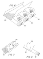
- FIGS. 6-8 An alternative apparatus embodiment of the present invention is illustrated in FIGS. 6-8 in which conveyor belt 60 and blowers 62 are positioned at an inclined angle with respect to horizontal.
- the path of the food product is illustrated by the line 64 in FIGS. 7 and 8.
- the product is moved by blowers 62 across conveyor belt 60 from right to left as illustrated in the figure and then the product falls back across conveyor belt 60 to the right towards the next blower.
- liquid cryogen injectors may also be provided along only one side, or on both sides, of the conveyor.
- FIGS. 9-11 Another alternative apparatus embodiment of the invention is illustrated in FIGS. 9-11.
- a V-shaped conveyor belt 70 is provided having two inclined portions meeting at a crest.
- Blowers 72 of this embodiment are positioned on either side of conveyor belt 70, and blow the product back and forth over the crest of conveyor belt 70.
- blowers 72 may be arranged either in an alternating or in an opposing arrangement.
- the path 74 of the product in this embodiment is illustrated in FIGS. 10 and 11.
- a multitier crossflow cryogenic freezer 78 includes a freezer apparatus 10.
- Freezer apparatus 10 comprises the first or top tier of freezer 78.
- a second tier 80 is located below freezer apparatus 10.
- a third tier 82 may optionally be provided below second tier 80, as well as additional tiers (not shown) serially below third tier 82.
- Second tier 80 and third tier 82 contain no source(s) of cryogen to cool the product passing through the tiers.
- Second tier 80 and third tier 82 may optionally include cross-flow blowers (not shown), similar to those described with reference to the embodiments illustrated in FIGS. 1-11.
- Cross-flow blowers draw used cryogen gas into second tier 80 and third tier 82, and move it toward exit 86 in the lowermost tier (in the embodiment illustrated in FIG. 12, the third tier).
- the use of cross-flow blowers increases the heat transfer from the product for the amount of cryogen used, and ensures that the used cryogen gas exits freezer 78 at exit 86.
- the flow of a product and used cryogen through freezer 78 is indicated by arrows 84.
- the product travels along freezer 10 and drops or is carried down to second tier 80.
- Second tier 80 moves the product in a direction opposite that of freezer 10.
- third tier 82 moves the product in a direction opposite that of second tier 80.
- additional tiers (not shown) are added, the product drops or is carried down to the next tier, which moves the product in a direction opposite from that of the tier from which they receive the product.
- the arrangement of the multiple tiers according to the embodiment illustrated in FIG. 12 provides the advantages of decreasing the footprint of the freezer 78 while providing a longer cooling conveyance path, and therefore longer residence time for a product passing though the freezer 78, than freezer 10 alone. Freezer 78 therefore also enables increased production rates through freezer 78.
- each of the inventive apparatus embodiments described provides an unobstructed side gas flow from the blowers and injectors which bathes the complete surface of each piece of product in a cold environment, causing rapid heat exchange and resulting in a very time efficient means of freezing.
- cold vapor is continuously recirculated through the freezing chamber by the blowers allowing for more efficient cryogen usage.
- the side mounted cryogen injection adds to the high velocity side to side air movement causing the product to be further agitated.
- the direct liquid/gas contact with the product causes the most rapid heat removal allowing for more product throughput per length of freezer.
- the resulting flash freezing leads to high quality IQF product.
- Product flow rates may range from about 500 pounds per hour up to about 4000 pounds per hour, but this is highly dependent on a combination of many factors, including the temperature of the product entering the freezer and the desired product exit temperature; the cryogen used; blower speed, and the like.
- a prototype freezer was built substantially in accordance with FIGs. 1-5 having a moving conveyor belt and six blowers, three blowers on each side.
- the main structural components (aside from the blowers, cryogen injectors and associated piping, and the like) were made from wood, although commercial units will be made of stainless steel (for the food industry).
- the blowers used were variable speed blowers, made by Dayton Co. model No. 7C639, although other equivalent blowers could have been used.
- the prototype allowed changing of the side wall shape during testing. Liquid nitrogen was used as the cryogen in all testing, which was injected in three injectors in the first blower on each side of the apparatus, as depicted in FIG. 2.
Landscapes
- Engineering & Computer Science (AREA)
- Chemical & Material Sciences (AREA)
- Life Sciences & Earth Sciences (AREA)
- Polymers & Plastics (AREA)
- Zoology (AREA)
- Food Science & Technology (AREA)
- Wood Science & Technology (AREA)
- Combustion & Propulsion (AREA)
- Physics & Mathematics (AREA)
- Mechanical Engineering (AREA)
- Thermal Sciences (AREA)
- General Engineering & Computer Science (AREA)
- Freezing, Cooling And Drying Of Foods (AREA)
Applications Claiming Priority (2)
| Application Number | Priority Date | Filing Date | Title |
|---|---|---|---|
| US08/805,916 US5765381A (en) | 1997-03-04 | 1997-03-04 | Multitier crossflow cryogenic freezer and method of use |
| US805916 | 1997-03-04 |
Publications (2)
| Publication Number | Publication Date |
|---|---|
| EP0863373A2 true EP0863373A2 (fr) | 1998-09-09 |
| EP0863373A3 EP0863373A3 (fr) | 2000-11-08 |
Family
ID=25192867
Family Applications (1)
| Application Number | Title | Priority Date | Filing Date |
|---|---|---|---|
| EP98400459A Withdrawn EP0863373A3 (fr) | 1997-03-04 | 1998-02-26 | Congélateur cryogénique à courant croisé et à plusieurs étages et procédé d'utlilisation |
Country Status (2)
| Country | Link |
|---|---|
| US (1) | US5765381A (fr) |
| EP (1) | EP0863373A3 (fr) |
Cited By (2)
| Publication number | Priority date | Publication date | Assignee | Title |
|---|---|---|---|---|
| EP1785043A1 (fr) * | 2005-11-15 | 2007-05-16 | L'AIR LIQUIDE, Société Anonyme pour l'Etude et l'Exploitation des Procédés Georges Claude | Procédé et appareil de refroidissement d'aliments |
| US11889844B2 (en) | 2017-10-26 | 2024-02-06 | Gea Food Solutions Bakel B.V. | Treatment of insects |
Families Citing this family (21)
| Publication number | Priority date | Publication date | Assignee | Title |
|---|---|---|---|---|
| US6178756B1 (en) | 1999-05-14 | 2001-01-30 | Tri-Gas, Inc. | Method and apparatus for chilling perishable liquids |
| FR2809481B1 (fr) * | 2000-05-23 | 2002-08-16 | Air Liquide | Ventilateur destine notamment a equiper un tunnel de refrigeration de produits tels que des produits alimentaires et tunnel equipe d'un ensemble de ces ventilateurs |
| NO316630B1 (no) * | 2001-10-29 | 2004-03-15 | Yara Int Asa | Fremgangsmate og anordning for kjoling og/eller frysing av produkter |
| BR0313529A (pt) * | 2002-08-16 | 2005-07-12 | Boc Group Inc | Método e aparelho para congelar crosta superficial de produto alimentìcio |
| US6877327B2 (en) * | 2002-08-20 | 2005-04-12 | The Boc Group, Inc. | Flow enhanced tunnel freezer |
| DE102004020193A1 (de) * | 2004-04-22 | 2005-11-17 | Linde Ag | Vorrichtung zum Kühlen und/oder Gefrieren von Produkten |
| US7197883B2 (en) * | 2005-05-06 | 2007-04-03 | Praxair Technology, Inc. | Cooling or heating with multi-pass fluid flow |
| DE102006045324A1 (de) * | 2006-09-22 | 2008-04-03 | Linde Ag | Vorrichtung zum schnellen Frosten von Stoffen |
| WO2009012780A2 (fr) * | 2007-07-25 | 2009-01-29 | Dantech Food Systems Pte Ltd. | Appareil pour traitement thermique par voie gazeuse |
| US8333087B2 (en) | 2007-08-13 | 2012-12-18 | Linde, Inc. | Cross-flow spiral heat transfer system |
| WO2009070586A1 (fr) * | 2007-11-27 | 2009-06-04 | Linde, Inc. | Système de congélateur tunnel à écoulement transversal |
| JP5143597B2 (ja) * | 2008-03-11 | 2013-02-13 | 株式会社テクニカン | 凍結物の製造方法および製造装置 |
| US20100162727A1 (en) * | 2008-12-31 | 2010-07-01 | Linde. Inc. | Freezer with pulse flow generator |
| WO2012050575A1 (fr) * | 2010-10-13 | 2012-04-19 | Linde Aktiengesellschaft | Système de transfert de chaleur spiral à flux transversal comportant une courroie transporteuse spirale auto-empilable |
| US8904811B2 (en) * | 2012-11-15 | 2014-12-09 | Linde Aktiengesellschaft | Baffle controlled oscillating flow freezer |
| US20140302207A1 (en) * | 2013-04-03 | 2014-10-09 | Meduri Farms, Inc. | Fruit breaking system and method |
| US9560868B2 (en) * | 2014-02-26 | 2017-02-07 | Inventure Foods, Inc. | System and method for fortifying fruits with vitamins |
| US9969569B2 (en) | 2015-09-22 | 2018-05-15 | Deere & Company | Agricultural vehicle pneumatic distribution system |
| GB2545515A (en) * | 2015-12-14 | 2017-06-21 | Linde Ag | Cryogenic impingement chilling for carcasses |
| CN106403458A (zh) * | 2016-11-23 | 2017-02-15 | 上海海洋大学 | 一种新型上下鼓风式速冻机孔板 |
| WO2020152288A1 (fr) * | 2019-01-24 | 2020-07-30 | BSH Hausgeräte GmbH | Dispositif d'évacuation des émanations pour plaque de cuisson et appareil combiné |
Family Cites Families (33)
| Publication number | Priority date | Publication date | Assignee | Title |
|---|---|---|---|---|
| US1865168A (en) * | 1930-03-25 | 1932-06-28 | Equity Construction Company In | Refrigerating method and apparatus |
| US2527542A (en) * | 1944-10-12 | 1950-10-31 | Rensselaer H Greene Van | Method and apparatus for freezing materials |
| US2677943A (en) * | 1951-07-13 | 1954-05-11 | Eskimo Pie Corp | Machine for manufacturing frozen confections |
| US3027728A (en) * | 1959-11-12 | 1962-04-03 | Greer J W Co | Chocolate confection cooling |
| US3553973A (en) * | 1966-06-23 | 1971-01-12 | Jack K Moran | Continuous freezer |
| US3507128A (en) * | 1967-12-22 | 1970-04-21 | Tom H Murphy | Continuous cryogenic process combining liquid gas and mechanical refrigeration |
| US3605434A (en) * | 1969-11-12 | 1971-09-20 | James L Foster | Refrigeration apparatus including a conveyor and employing cryogenic fluid |
| US3708995A (en) * | 1971-03-08 | 1973-01-09 | D Berg | Carbon dioxide food freezing method and apparatus |
| US3813895A (en) * | 1972-09-28 | 1974-06-04 | Air Prod & Chem | Food freezing apparatus |
| GB1452082A (en) * | 1972-10-31 | 1976-10-06 | Osaka Gas Co Ltd | Method and an apparatus for cooling goods by contacting the goods with a low temperature gas |
| US3892104A (en) * | 1973-09-20 | 1975-07-01 | David J Klee | Cryogenic freezer with variable speed gas control system |
| US4086784A (en) * | 1976-12-15 | 1978-05-02 | Hollymatic Corporation | Apparatus for refrigerating articles |
| US4157018A (en) * | 1977-05-06 | 1979-06-05 | Teckton, Inc. | Machines for conveying articles through a heat transfer medium |
| US4481782A (en) * | 1983-01-25 | 1984-11-13 | The Boc Group, Inc. | Methods and apparatus for refrigerating products |
| US4475351A (en) * | 1983-08-09 | 1984-10-09 | Air Products And Chemicals, Inc. | Dual-flow cryogenic freezer |
| GB8611539D0 (en) * | 1986-05-12 | 1986-06-18 | Boc Group Plc | Food freezing apparatus |
| FR2600406B1 (fr) * | 1986-06-18 | 1988-08-05 | Air Liquide | Procede et tunnel de refroidissement |
| US4726766A (en) * | 1986-12-01 | 1988-02-23 | Stewart Systems, Inc. | Air circulation and exhaust control system for commerical ovens |
| US4912943A (en) * | 1988-12-14 | 1990-04-03 | Liquid Air Corporation | Method and apparatus for enhancing production capacity and flexibility of a multi-tier refrigeration tunnel |
| US5205135A (en) * | 1991-11-13 | 1993-04-27 | Liquid Carbonic Corporation | Helical conveyor freezer |
| FR2686403B1 (fr) * | 1992-01-21 | 2001-02-09 | Air Liquide | Procede et dispositif de congelation. |
| US5343714A (en) * | 1992-05-20 | 1994-09-06 | Air Products And Chemicals, Inc. | Spiral freezer |
| US5335503A (en) * | 1992-06-10 | 1994-08-09 | The Boc Group, Inc. | Cooling method and apparatus |
| NZ250270A (en) * | 1992-12-29 | 1995-07-26 | Boc Group Inc | Freezing food using liquid refrigerant: turbulent flow of refrigerant induced in trough type conveyor |
| US5335504A (en) * | 1993-03-05 | 1994-08-09 | The M. W. Kellogg Company | Carbon dioxide recovery process |
| GB2286657A (en) * | 1994-02-14 | 1995-08-23 | Boc Group Plc | Immersion freezer |
| GB9402855D0 (en) * | 1994-02-15 | 1994-04-06 | Air Prod & Chem | Tunnel freezer |
| GB9402884D0 (en) * | 1994-02-15 | 1994-04-06 | Air Prod & Chem | Tunnel freezer |
| GB9402840D0 (en) * | 1994-02-15 | 1994-04-06 | Air Prod & Chem | Tunnel freezer |
| US5444985A (en) * | 1994-05-13 | 1995-08-29 | Liquid Carbonic Corporation | Cryogenic tunnel freezer |
| US5509277A (en) * | 1994-12-14 | 1996-04-23 | Air Products And Chemicals, Inc. | Combination immersion/impingement tunnel freezer |
| AU718112B2 (en) * | 1995-03-28 | 2000-04-06 | Boc Group, Inc., The | Apparatus and method for freezing food products |
| US5606861A (en) * | 1995-06-07 | 1997-03-04 | Air Liquide America Corporation | Crossflow cryogenic freezer and method of use |
-
1997
- 1997-03-04 US US08/805,916 patent/US5765381A/en not_active Expired - Fee Related
-
1998
- 1998-02-26 EP EP98400459A patent/EP0863373A3/fr not_active Withdrawn
Non-Patent Citations (1)
| Title |
|---|
| None |
Cited By (3)
| Publication number | Priority date | Publication date | Assignee | Title |
|---|---|---|---|---|
| EP1785043A1 (fr) * | 2005-11-15 | 2007-05-16 | L'AIR LIQUIDE, Société Anonyme pour l'Etude et l'Exploitation des Procédés Georges Claude | Procédé et appareil de refroidissement d'aliments |
| WO2007057330A1 (fr) * | 2005-11-15 | 2007-05-24 | L'air Liquide Societe Anonyme Pour L'etude Et L'exploitation Des Procedes Georges Claude | Procede et dispositif de refroidissement d'articles alimentaires |
| US11889844B2 (en) | 2017-10-26 | 2024-02-06 | Gea Food Solutions Bakel B.V. | Treatment of insects |
Also Published As
| Publication number | Publication date |
|---|---|
| US5765381A (en) | 1998-06-16 |
| EP0863373A3 (fr) | 2000-11-08 |
Similar Documents
| Publication | Publication Date | Title |
|---|---|---|
| US5765381A (en) | Multitier crossflow cryogenic freezer and method of use | |
| US5606861A (en) | Crossflow cryogenic freezer and method of use | |
| US6334330B2 (en) | Impingement cooler | |
| CA2280199C (fr) | Refroidisseur a inertie | |
| US4481782A (en) | Methods and apparatus for refrigerating products | |
| US6895775B2 (en) | Apparatus for surface crust freezing of food product | |
| US5878582A (en) | Method and apparatus for freezing food products | |
| MXPA05001810A (es) | Congelador de tunel de flujo mejorado. | |
| US6418834B1 (en) | Apparatus for treating an item during travel of the item along a treating trough | |
| EP3290834B1 (fr) | Impacteur servant à refroidir ou congeler des produits et processus/procédé correspondant | |
| US6912869B2 (en) | Helical impingement cooling and heating | |
| EP1214553B1 (fr) | Chambre et procede de traitement thermique | |
| US20070169630A1 (en) | Thermal processing chamber and conveyor belt for use therein and method of processing product | |
| US5222363A (en) | Fluidized bed air cooling system | |
| EP0846928B1 (fr) | Appareil pour surgeler des produits alimentaires en continu | |
| KR102176270B1 (ko) | 개별 신선 냉동(Individual Fresh Frozen)을 이용한 닭고기 냉동 방법 및 장치 | |
| SU1750599A1 (ru) | Устройство дл охлаждени изделий | |
| CA2533223C (fr) | Chambre de traitement thermique et bande transporteuse associee, et methode de traitement d'article | |
| NZ314047A (en) | Conveying apparatus with a plenum chamber beneath the perforated bottom of a trough, typically for heating or cooling food down spiralling trough | |
| AU4575102A (en) | Food treating device |
Legal Events
| Date | Code | Title | Description |
|---|---|---|---|
| PUAI | Public reference made under article 153(3) epc to a published international application that has entered the european phase |
Free format text: ORIGINAL CODE: 0009012 |
|
| AK | Designated contracting states |
Kind code of ref document: A2 Designated state(s): DE ES FR GB IT |
|
| PUAL | Search report despatched |
Free format text: ORIGINAL CODE: 0009013 |
|
| AK | Designated contracting states |
Kind code of ref document: A3 Designated state(s): AT BE CH DE DK ES FI FR GB GR IE IT LI LU MC NL PT SE |
|
| 17P | Request for examination filed |
Effective date: 20010508 |
|
| AKX | Designation fees paid |
Free format text: DE ES FR GB IT |
|
| RAP1 | Party data changed (applicant data changed or rights of an application transferred) |
Owner name: L'AIR LIQUIDE, S.A. A DIRECTOIRE ET CONSEIL DE SUR |
|
| STAA | Information on the status of an ep patent application or granted ep patent |
Free format text: STATUS: THE APPLICATION HAS BEEN WITHDRAWN |
|
| 18W | Application withdrawn |
Withdrawal date: 20020529 |