EP0863404B1 - Procédé et appareil de détection de la vitesse d'un moteur à partir du son émis - Google Patents
Procédé et appareil de détection de la vitesse d'un moteur à partir du son émis Download PDFInfo
- Publication number
- EP0863404B1 EP0863404B1 EP97890052A EP97890052A EP0863404B1 EP 0863404 B1 EP0863404 B1 EP 0863404B1 EP 97890052 A EP97890052 A EP 97890052A EP 97890052 A EP97890052 A EP 97890052A EP 0863404 B1 EP0863404 B1 EP 0863404B1
- Authority
- EP
- European Patent Office
- Prior art keywords
- signal
- speed
- engine
- engine speed
- measurement
- Prior art date
- Legal status (The legal status is an assumption and is not a legal conclusion. Google has not performed a legal analysis and makes no representation as to the accuracy of the status listed.)
- Expired - Lifetime
Links
- 238000000034 method Methods 0.000 title claims description 59
- 238000001514 detection method Methods 0.000 title claims description 5
- 238000004458 analytical method Methods 0.000 claims description 60
- 238000005259 measurement Methods 0.000 claims description 57
- 238000002485 combustion reaction Methods 0.000 claims description 47
- 238000011156 evaluation Methods 0.000 claims description 43
- 230000009466 transformation Effects 0.000 claims description 27
- 238000011835 investigation Methods 0.000 claims description 10
- 230000001419 dependent effect Effects 0.000 claims description 8
- 230000008859 change Effects 0.000 claims description 6
- 230000008569 process Effects 0.000 claims description 5
- 238000012937 correction Methods 0.000 claims description 4
- 238000006243 chemical reaction Methods 0.000 claims description 2
- 230000003321 amplification Effects 0.000 claims 1
- 238000013208 measuring procedure Methods 0.000 claims 1
- 238000003199 nucleic acid amplification method Methods 0.000 claims 1
- 230000005236 sound signal Effects 0.000 description 20
- 238000001228 spectrum Methods 0.000 description 19
- 238000002347 injection Methods 0.000 description 7
- 239000007924 injection Substances 0.000 description 7
- 238000004364 calculation method Methods 0.000 description 6
- 230000006872 improvement Effects 0.000 description 6
- 230000003595 spectral effect Effects 0.000 description 6
- 230000001052 transient effect Effects 0.000 description 5
- 230000001133 acceleration Effects 0.000 description 4
- 230000000737 periodic effect Effects 0.000 description 4
- 230000002123 temporal effect Effects 0.000 description 4
- 238000005070 sampling Methods 0.000 description 3
- 238000012360 testing method Methods 0.000 description 3
- 238000012935 Averaging Methods 0.000 description 2
- 238000005311 autocorrelation function Methods 0.000 description 2
- 239000000203 mixture Substances 0.000 description 2
- 239000003921 oil Substances 0.000 description 2
- 238000010845 search algorithm Methods 0.000 description 2
- 230000036962 time dependent Effects 0.000 description 2
- YZSCPLGKKMSBMV-UHFFFAOYSA-N 5-fluoro-4-(8-fluoro-4-propan-2-yl-2,3-dihydro-1,4-benzoxazin-6-yl)-N-[5-(1-methylpiperidin-4-yl)pyridin-2-yl]pyrimidin-2-amine Chemical compound FC=1C(=NC(=NC=1)NC1=NC=C(C=C1)C1CCN(CC1)C)C1=CC2=C(OCCN2C(C)C)C(=C1)F YZSCPLGKKMSBMV-UHFFFAOYSA-N 0.000 description 1
- 230000005526 G1 to G0 transition Effects 0.000 description 1
- 238000012952 Resampling Methods 0.000 description 1
- 230000003044 adaptive effect Effects 0.000 description 1
- 239000000654 additive Substances 0.000 description 1
- 230000000996 additive effect Effects 0.000 description 1
- 238000013459 approach Methods 0.000 description 1
- 235000019504 cigarettes Nutrition 0.000 description 1
- 239000003086 colorant Substances 0.000 description 1
- 230000003750 conditioning effect Effects 0.000 description 1
- 238000013461 design Methods 0.000 description 1
- 238000010586 diagram Methods 0.000 description 1
- 230000000694 effects Effects 0.000 description 1
- 238000010616 electrical installation Methods 0.000 description 1
- 230000005284 excitation Effects 0.000 description 1
- 238000000695 excitation spectrum Methods 0.000 description 1
- 238000002474 experimental method Methods 0.000 description 1
- 238000010304 firing Methods 0.000 description 1
- 238000009472 formulation Methods 0.000 description 1
- 230000001939 inductive effect Effects 0.000 description 1
- 230000002045 lasting effect Effects 0.000 description 1
- 239000010687 lubricating oil Substances 0.000 description 1
- 238000005457 optimization Methods 0.000 description 1
- 238000012545 processing Methods 0.000 description 1
- 230000004044 response Effects 0.000 description 1
- 238000004611 spectroscopical analysis Methods 0.000 description 1
- 238000010183 spectrum analysis Methods 0.000 description 1
- 230000001629 suppression Effects 0.000 description 1
- 230000001360 synchronised effect Effects 0.000 description 1
- 238000010792 warming Methods 0.000 description 1
Images


Classifications
-
- G—PHYSICS
- G01—MEASURING; TESTING
- G01P—MEASURING LINEAR OR ANGULAR SPEED, ACCELERATION, DECELERATION, OR SHOCK; INDICATING PRESENCE, ABSENCE, OR DIRECTION, OF MOVEMENT
- G01P3/00—Measuring linear or angular speed; Measuring differences of linear or angular speeds
- G01P3/42—Devices characterised by the use of electric or magnetic means
- G01P3/44—Devices characterised by the use of electric or magnetic means for measuring angular speed
- G01P3/48—Devices characterised by the use of electric or magnetic means for measuring angular speed by measuring frequency of generated current or voltage
Definitions
- the invention relates to a method for determining the rotational speed of an internal combustion engine, wherein the sound generated by the machine is continuously detected and converted into an electrical Measuring signal is converted, and wherein the measuring signal to the obtained speed information examined and the result to determine a measure of the speed is used. Furthermore, the invention also relates to a device for determining the Speed of an internal combustion engine using such a method, with an arranged at least in the vicinity of the internal combustion engine sound sensor to the continuous Detecting the sound generated by the machine and converting it into an electrical one Signal and associated therewith and with an output unit evaluation.
- the object of the invention is the disadvantages of the known arrangements and to avoid procedures and in particular a simple and generally applicable
- the present invention is based on the consideration that the previously known Methods and arrangements for speed determination of internal combustion engines under Evaluation of sound signals of the internal combustion engine essentially therefore not for dynamic measurements are suitable because they use signal analysis methods, the are only suitable for stationary signals, and / or because so-called tracking systems used which, of course, always lag behind in dynamic measuring mode Correction and search algorithms can be used for the individual speed determinations. Accordingly, according to the present invention, a kind of "forward strategy" is used, by two simultaneously existing measurement characteristics for the speed sought together be evaluated - the one for the rough estimate of an auxiliary speed for the required time-axis transformation, the other for the actual, signal-analytical determination the speed based on the transformed axis.
- an auxiliary quantity will now be considered first determined, with the respective speed in principle only in an approximate Must be related, which is also non-linear and / or error-prone may be and of course preferably approximately proportional to the speed and should be easily determinable, but beyond that is uncritical.
- auxiliary size come many identifiable engine or vehicle sizes with speed-dependent features in question, as the skilled artisan easily recognize and can choose appropriate to a particular application.
- pneumatic e.g., crankcase pressure
- hydraulic e.g. the lubricating oil supply
- electrical for example from the electrical Installation of the vehicle
- the Back pressure in the exhaust because he was about at the beginning already mentioned Abgassmeßellon is easily additional measurable.
- a in arranged on or outside the vehicle Airborne microphone in the vicinity of the internal combustion engine or of their exhaust in question.
- roughly speed-proportional auxiliary size directly a level size the recorded structure-borne sound signal used. This can be done by the operating staff be prompted in a calibration procedure, the engine at operate stationary at least two different speeds, preferably idle (expected range 350 to 1200 rpm) and upper Idling (expected range 1500 to 6000 rpm).
- the time-dependent determined measuring signal by means of a signal-analytical Method based on the approximate crank angle proportional Size is examined, the analysis method mentioned above, from the estimated speed (k) for the transformation of the time axis used on the approximate crank angle proportional size and off determined the result of the investigation, the measure of the speed becomes.
- crank angle dependence Signal analyzed by appropriate signal analysis methods.
- the transformation of the time axis is approximated to the crankshaft-proportional size de facto in the method of signal analysis built-in. Both ultimately provide the intended and highly dynamic Applications suitable investigation of basically dependent from the time determined measuring signal based on the approximate crank angle proportional Size.
- a calibrated relationship between a Intensticians slaughter of the detected sound and the signal-analytically determined Speed can be used, this calibration preferably before implementation the measurement carried out at at least two stationary speeds becomes.
- intensity measures for the sound signal There are a variety of known intensity measures for the sound signal.
- sound level defined in the literature with different Frequency ratings defined are also sound levels with special frequency ratings.
- the determined measures for already determined speeds can after a particularly preferred further embodiment of the invention for tracking or improvement of the calibration parameters for subsequent determinations be used. It is not, as in the beginning addressed to subsequent corrections of individual measurement results or order the projecting of current measured values into the future, which experience has shown to be dynamic Operation always to inaccuracies or smearings over the Timeline and possibly leads to instabilities of the gauge, but to adaptive improvements of the calibration parameters that are not immediate at the respective measuring point but only in total by an improvement of the evaluation, especially in terms of measurement accuracy, reliability and success rate even at transient speeds, make noticeable.
- the search for the significant peak in Result history supported by the application of a weight function Within a search and expectation range of the abscissa around the ideal value is to emphasize the course and its maxima and outside be weakened. In this way, the probably significant peak be highlighted under other peaks.
- Time axis transformation is particularly advantageous in that the search and Expected range regardless of the respective speed always in the same Area of the abscissa can be spanned and not possibly constantly and rapidly changing speeds must be tracked.
- n is from the in the signal analysis flowed through values of the auxiliary speed, or the factor (k) by Averaging a reference auxiliary speed, or a reference factor (K) formed, and just corrected the registered deviation from the ideal value.
- the significant peak in the result So in the simplest case it can be the highest peak in the vicinity of the abscissa ideal value be taken.
- An improved suppression of eventually Existing interference is through the use of the above Weight function achieved by e.g. the highest weighted peak as significant peak is taken.
- the deviation of the as significantly abscissa value are taken from the ideal value.
- the large deviation may not be as significant as the resulting speed evaluated and / or the speed determining personnel performing be displayed accordingly.
- the preferred safety measure a kind of signal-to-noise ratio evaluated in the result of the signal analysis. This is a regression line over all values of the result curve in the search and expectation range the signal analysis and as security value of a found peak and thus an associated speed value becomes the value of the regression line at this Position exceeding the height of the peak relative to the height of the search and expectation area taken absolutely highest peak.
- a speed value is considered safe only if if the safety measure of the associated tip lies within a tolerance band, or a minimum value.
- a feature (L) of the at Internal combustion engine recorded signal preferably the measuring signal (u (t)) itself
- the factor (k) for the time axis transformation is therefore proportional to one rough estimate of the
- the factor (k) is the factor (k) proportional to the approximation of the respective one Differential quotient (da / dt) of the continuous course of approximate crank angle proportional magnitude (a) over time (t) and to view use.
- the Factor (k) proportional to the approximation of the corresponding difference quotient (.DELTA.a / .DELTA.t) and is therefore for approximate conversion of the discrete time intervals ( ⁇ t) in discrete intervals ( ⁇ a) of size (a) and to carry out the actual signal analysis used.
- the result size (E) of the actual signal analysis on the base is formed of the size (a), it also needs a back transformation in the The time domain.
- the time is indeed the basis of the speed indication.
- To this Purpose becomes from the values used for the determination of the result size (E) of the factor (k) determines a reference factor (K) by means of which the crank angle-related Result in a time-related result, namely the speed, is converted.
- the reference factor (K) has the same dimension as the factor (k) and is e.g. in the case of spectral or cepstral analysis, the mean of the course of the factor (k) used for the analysis in the evaluation area.
- the reference factor (K) has the meaning of a mean auxiliary speed.
- the latter FTT is also a process that is also special for the temporally high-resolution frequency analysis is indicated.
- Purpose have become known, for example, the Fourier short-time spectroscopy for the calculation of so-called spectrograms, the Wigrier-Ville distribution and the different variants of wavelet analysis.
- the function variable of the signal u is the time
- the function variable of the spectrum obtained after the first Fourier transform has the dimension of a frequency
- the function variable of the cepstrum again the dimension of a time bearing the art name queference.
- the queference specifies the spectral period number per frequency unit (Hertz).
- Kepstrum analysis based on the crank angle, or a to proportional size, such as the number of cycles, so has the function variable of the spectrum the dimension atomic number (i.e. period number per revolution, or cycle) and that of the cepstrum again the dimension of a crank angle, or a number of cycles.
- the estimation unit one from the Signal of the sound sensor an intensity measurement intensity measuring unit for determining the factor k, wherein both the evaluation device as well as the transformation unit, the estimation unit and the intensity measuring unit be implemented in terms of hardware as well as software can.
- a Device designed to carry out the method according to the invention, in that the output unit connected to the evaluation device Elements for indicating a non-significant speed determination and / or to request to change the location of sound detection, and / or to Indication that only the estimated speed is output has what the normal measuring operation with such a device much easier.
- a further embodiment of the invention is a the entire Ausreteund Calibration procedure of a measuring process controlling unit provided, preferably also those for the determination and improvement of the calibration parameters (P) suitable measuring signals and operating conditions of the internal combustion engine determined automatically. So the user does not have to be special Dialogue with the measuring device or a certain sequence in Maintain engine operation. Because of the estimation unit and the evaluation unit determined sequence of values for the intensity measure, the auxiliary speed, the speed and the safety measure are given by the control unit Signals to the output unit and preferably also to the calibration unit, so that on the one hand the user on the respective full or readiness of the system is always informed and on the other hand a determination and improvement of the calibration parameters takes place automatically, whenever that due to a detected as stationary speed and a sufficient safety is reasonable and possible.
- P calibration parameters
- the sound sensor provided for the speed determination according to the invention has both an airborne sound sensor and a structure-borne sound sensor. This gives the user the greatest possible freedom in attaching the Sound sensor given, because one of the two signal sources delivers with great Probability a useful signal for the speed determination.
- the control unit automatically amplifies, mixing, Selection and assignment of the two, preferably in common housing arranged sensors emitted signals to an auxiliary signal for the Determining the auxiliary speed and a main signal for the determination of Speed controls. This ensures that the signal, the speed values allowed to determine with the greatest safety measure, indeed is used. It may be advantageous to main and auxiliary signal the Assign to two different signal sources, or in particular a Mixed signal from the two brought to approximately the same level signals generate and use for the speed determination according to the invention.
- a structure-borne sound sensor with a Magnetic base mounted on a suitable component of the engine or vehicle As an attachment point have, inter alia, cylinder head bolts, engine mounting eyelets, Engine block, oil drain plug, vehicle frame, etc. proven. But also with a microphone near the engine or the vehicle Recorded airborne sound allows the speed determination by the same procedure and with similarly good results as the structure-borne noise, such as experiments have shown. It is therefore also to a measuring device with both a Structure-borne sound as well as an airborne sound sensor thought, in which either the each better measuring signal selected or at the two signals in level be coordinated with each other and formed from a mixed signal and the Speed determination is used.
- At least one sound sensor including preamplifier Measurement signal is an anti-aliasing filter (cutoff frequency between 5 and 20 kHz) and a digitizer (sampling rate at least 2 times Cutoff frequency of the anti-aliasing filter).
- the digitally displayed Signal is processed in a computer or signal processor.
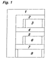
- the measuring system waits that the operator follows the displayed message and the sensor at a suitable location. As soon as and as long as a measuring signal sufficient amplitude is available, the loop core (2 to 8) to be processed; otherwise the measurement will stop and a new one may be to be started.
- the system expects the Engine stationary in lower idle running.
- the speed of the engine e.g., 660 rpm
- a security measure as described above, e.g. the relative height of the relevant peak in the cepstrum, sufficiently high is, e.g. 80%.
- This speed and the associated value of the intensity measure form a first value pair for the calibration of the relationship between Speed and intensity measure.
- block 4 the user is given the successful completion of block 3 and so that the appropriate sensor attachment together with the determined speed displayed.
- loop 5 and block 6 the system expects a second steady state Operating point of the engine at increased idling. Just like in loop 2 and Block 3 is given for the steady state and with the help of a second predetermined rough estimation of the speed of the motor (e.g., 3000 rpm) a second pair of trusted value for speed and intensity measure determined.
- a second predetermined rough estimation of the speed of the motor e.g., 3000 rpm
- the user is successful in performing the calibration phase displayed.
- the measuring system is ready, in block 8, the inventive Method for speed determination even with highly dynamic To perform speed changes and continuously the respective speed, for example with a refresh rate of 2 to 10 Hz.
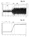
- FIG. 2a shows the time profile of a typical measurement signal (u_t) (corresponds to (u (t)), which in this case with a at the oil drain plug of a typical 6-cylinder truck diesel engine mounted structure-borne sound sensor during a phase in low idle, an acceleration phase and a phase was measured at increased idle at Abregelcard. Furthermore, Fig. 2a dashed lines drawn the course of the detected from the measurement signal Intensity measure (L), which in this case as by a moving averaging smoothed absolute value of the one with a high pass (cutoff frequency 1500 Hz) filtered measuring signal (u_t) was determined.
- Intensity measure L
- FIG. 2b shows, at the same time as FIG. 2a, the curves of the intensity measure (L) certain auxiliary speed (n_L) compared to the reference speed (n_Ref_t) of the engine.
- the reference speed was independent of the invention System and measured for comparison purposes only, with an on a diesel injection line clamped clamp for detecting the at each Cycle occurring injection pressure peaks and thus for measuring the injection period, or the engine speed was used.
- FIGS. 3 to 5 the inventive speed determination of the easier to understand because of the measured sound signal, but be explained on the basis of a synthetic waveform.
- the signal was chosen so that essential characteristics of the motor can be measured Sound signals are recognizable, in particular the periodicity in the basic cycle frequency and in the ignition frequency as well as a characteristic content associated overtones.
- As vivid, simple and sufficiently realistic has proved to be a square wave, in which every combustion assigned sound signal through a rectangle and the existing at each engine Inequality between the individual cylinders of the engine and the associated with them sound signals by an elevation of only one rectangle is displayed per cycle.
- the selection was made as for the measuring signals of Fig. 2 is a 6-cylinder engine.
- the calculation of the synthetic signal was carried out at the same time as Fig. 2 and took place exactly after the measured reference speed curve shown there (N_Ref_t). The duration of each rectangular period was just chosen so that they with the from the respective mean reference speed This timing matches the ignition period of the engine.
- the temporal resolution (sampling rate) of the synthetic signal is 4096 Points per second.
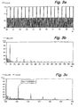
- Fig. 3a shows the time course of the synthetic signal (u_t_s_oll) in the period 10 indicated in FIG. 2, for a stationary one Operating point at increased idle, at the Abregelcardiere.
- Fig. 3b shows that from the signal of Fig. 3a after a simple time-based FFT (fast Fourier transform) obtained amplitude spectrum. For which gives 4096 points of the signal in the time window (10) of 6.0 to 7.0 sec the FFT 2048 frequency points and a frequency resolution of 1 Hz. One recognizes clearly that in the cycle frequency and in the ignition frequency harmonic Spectrum.
- FFT fast Fourier transform
- FIG. 3 c shows a time-based calculation of the frequency spectrum (FIG. 3 a) Cepstrum of the synthetic signal (Fig. 3a), wherein the spectrum only the section was used until 1024 Hz.
- the calculation was done by logarithmizing the amplitude spectrum and subsequent Fourier transformation with representation of the amount.
- abscissa value zero whose meaning with the "Similarity of the signal to itself" can be paraphrased
- dew abscissa value
- Fig. 4a shows the time course of the synthetic signal in Period 11.
- the synthetic signal clearly indicates the change in the Recognize period duration, which is not so obvious in the measured sound signal would.
- FIG. 4b shows the frequency spectrum calculated time-based as in FIG. 3b to the signal of Fig. 4a
- Fig. 4c shows the associated time-based cepstrum. It can be seen that the gradients are "smeared", so that no significant Tips can be found.
- the crux of the present invention is that the time base underlying the analysis of the measurement signal is transformed by means of a roughly estimated auxiliary speed such that the "smearing" of the analysis results shown in FIG. 4 is largely prevented. This is achieved if the analysis is based on a basis proportional to the approximate crank angle of the engine instead of the time base.
- the time interval ⁇ t underlying a digital-electronic data processing, for example the sampling interval, is therefore proportional to a crank angle-proportional interval ⁇ a.
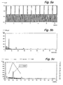
- Fig. 5a shows the application of this time axis transformation to the synthetic signal in the transient period 11, the run-up. you detects that the waveform applied over the approximate cycle number a stationary looks.
- the application of the cycle-number-based spectrum analysis ( Figure 5b) and cepstrum analysis ( Figure 5c) produces an appearance Similar result as the time-based shown in Fig. 3b and Fig. 3c Analysis of the Stationary Signal of FIG. 3a.
- Figure 5b cycle-number-based spectrum analysis
- Figure 5c cepstrum analysis
- the application of the time axis transformation shown in FIG Signal for subsequent signal analysis evaluation can be optimized be by adding the computational effort through an interpolating resampling a constant score per cycle number is reduced. This has further to Consequence that for a given score of, for example, 2048 points per FFT the temporal window width at high speeds low and low Speeds is comparatively longer, which has advantages in the accuracy of measurement and effected in the temporal measurement resolution.
- time axis transformation according to the invention As shown in Fig. 5 - also in the signal-analytical method can be incorporated as shown by a simple, analytically presented Fourier transformation is to be shown, of which a corresponding discrete-time Representation can be easily derived using the usual methods can.
- the order analysis can therefore also with the help of a modified Fourier transformation directly from the temporal course of the signal and the time course of the auxiliary speed can be performed.
- Fig. 5c is also in the search and expectation range of 0.5 to 2 Cycles determined regression line (regression) to determine the safety measure entered.
- Weight is the cepstral curve (cep_s_a) near the cycle number 1, thus facilitating the search for the speed-significant peak.
- the weighted Kepstral course (cep_g) is shown in dotted lines.
- the number of cycles (A) is also entered as the result (E) of the cepstral analysis at 1.0339: here, the abscissa value at the highest peak in the weighted cepstrum.
- This value, or its deviation from the number of cycles 1 means that the values of the auxiliary speed on which the time transformation was based were too large on average by 3.39%.
- the mean value of the auxiliary speed curve was 1511 1 / min, as entered in the table.
- the measurement error in this example is only 4 [1 / min] or 0.3%, which is a good result in view of the highly dynamic speed change.
- the deviation of the estimated speed (naux) from the determined Speed (n) in this example is +50 [1 / min] or +3.39%. This is in any case, this deviation is less than a maximum permissible deviation for example - 50% and + 100%, and the speed could cope in be determined in this search area.
- the safety measure determined for the tip in FIG. 5c is 89.4%. and is thus much larger than a minimum allowable value of, for example 60%, so that the determined speed confirmed as significant becomes.
- the determined speed can be trusted Value to be displayed and there is no need to place of which to display the auxiliary speed and inform the user about it.
- Fig. 6 is a device for carrying out the inventive Shown method.
- a sensor unit 12 which in the example shown in a housing both an airborne sound sensor (microphone) for airborne sound 13 and a structure-borne sound sensor (e.g., acceleration sensor) for body sound 14 with the help of a Magnetfußes 15 directly to the internal combustion engine 16, or possibly also e.g. on the vehicle frame or on a near the Vehicle mounted tripod, attached.
- the detected signals 17 are fed to a signal conditioning unit 18 and amplified there, filtered and optionally digitized that both a main signal 19 of the Evaluation unit 25 and an auxiliary signal 20 of the estimation unit 21 supplied can be.
- a control unit 36 controls the gain, and optionally Mixture of the signals 17 and their assignment to the main signal 19th and auxiliary signal 20.
- the estimation unit 21 includes an intensity measuring unit 22 in which the auxiliary signal 20 continuously an intensity measure and from this an auxiliary speed 24, or a factor (k), is determined for the time axis transformation.
- the Calibration parameters required for the estimation are included in one of the Control unit 36 controlled calibration unit 23 at the beginning of a measurement process first determined and then constantly improved.
- the evaluation unit 25 contains a transformation unit 26, in which from the transmitted from the estimation unit 21 auxiliary speed 24, or the Factor (k), the new basis (a) for the actual signal analyzer 27 performed analysis of the main signal 19 is formed.
- the security measurement unit 28 is checked whether the analysis result is a clear Speed determination with sufficient significance allows and whether the safety measure the new speed value is sufficiently high.
- the speed determination unit 29 becomes the auxiliary speed values used in the analysis 24, or the factor (k), a reference auxiliary speed (naux), or a Reference factor (K), formed and thus from the analysis result, the speed 30th certainly.
- the control unit 36 is, as already mentioned, for the control of entire evaluation and calibration procedure (see Fig. 1) and for the meaningful Coordination of the various units and their functions. she helps the entire device also to an attractive and user-friendly User interface, so that the speed measurement on largely All vehicles even during the run-up easily and safely carried out can be.
Landscapes
- Physics & Mathematics (AREA)
- General Physics & Mathematics (AREA)
- Combined Controls Of Internal Combustion Engines (AREA)
- Testing Of Engines (AREA)
Claims (16)
- Procédé de détermination de la vitesse de rotation (n) d'un moteur à combustion interne, le son produit par la machine étant détecté de façon continue et converti en un signal de mesure électrique (u(t)), le signal de mesure (u(t)) étant examiné pour y trouver l'information contenue de vitesse de rotation et le résultat étant utilisé pour déterminer une indication quantitative de la vitesse de rotation (n), caractérisé para) une estimation grossière de la vitesse de rotation respective du moteur à combustion interne et la détermination d'un facteur (k(t)) à partir de la vitesse de rotation estimée et du nombre de temps connu du moteur à combustion interne,b) détermination d'une grandeur a à peu près proportionnelle à l'angle de vibrequin à partir de la relation delta_a=k(t)* delta_t respectivement da=k(t)*dt,c) évaluation analytique d'après les signaux, du signal (u(t)) à l'aide et/ou sur la base de la grandeur a,d) détermination de l'indication quantitative de la vitesse de rotation (n) à partir du résultat de l'évaluation analytique par l'examen des signaux, effectué sur le signal (u(t)).
- Procédé selon la revendication 1, caractérisé en ce que le signal de mesure (u(t)), lors de l'examen, est transformé au moyen du facteur (k) sur un signal d'allure de courbe (u(a)) dépendant de l'angle de vibrequin, et ce signal d'allure étant utilisé pour déterminer l'indication quantitative de la vitesse de rotation, par examen basé sur la grandeur (a), à peu proportionnelle à l'angle de vibrequin.
- Procédé selon la revendication 1, caractérisé en ce que le signal de mesure (u(t)) est examiné à l'aide d'un procédé analytique opérant sur les signaux, basé sur l'angle de vibrequin (a), le procédé d'analyse utilisant le facteur (k) pour la transformation de l'axe des temps (t) à la grandeur (a) à peu proportionnelle à l'angle de vibrequin et déterminant l'indication quantitative de la vitesse de rotation (n), à partir du résultat d'examen ainsi obtenu.
- Procédé selon une des revendications 1 à 3, caractérisé en ce que, pour estimer la vitesse de rotation (n) spécifique, est utilisée une liaison étalonnée, entre une indication d'intensité du bruit détecté et la vitesse de rotation (n).
- Procédé selon la revendication 4, caractérisé en ce que l'étalonnage est effectué avant d'effectuer la mesure, pour au moins deux vitesses de rotation stationnaires (n).
- Procédé selon une ou plusieurs des revendications 1 à 5, caractérisé en ce que les grandeurs de mesure déterminées, pour des vitesses de rotation (n) déjà déterminées, sont utilisées pour asservir ou améliorer les paramètres d'étalonnage pour des estimations subséquentes.
- Procédé selon une ou plusieurs des revendications 1 à 6, caractérisé en ce que, pour déterminer le pic de signal, significatif pour la détermination de la vitesse de rotation, dans l'allure obtenue en résultat de l'analyse des signaux sur une plage de recherche autour de la valeur idéale en abscisse de préférence dans la zone comprise entre 0,5 fois et 2 fois cette valeur idéale, on fait intervenir une fonction de pondération.
- Procédé selon une ou plusieurs des revendications 1 à 7, caractérisé en ce que, pour déterminer le pic de signal significatif pour la détermination de la vitesse de rotation, dans l'allure obtenue en résultat de l'analyse des signaux, pour le pic de signal maximum déterminé dans la plage examinée, on forme une valeur de confiance et le pic ayant le niveau de confiance maximal est pris comme étant le pic significatif.
- Procédé selon une ou plusieurs des revendications 1 à 8, caractérisé en ce que chaque fois, pour la vitesse de rotation déterminée, on forme et on vérifie une valeur de confiance, et en ce que, dans le cas ou une valeur de confiance est hors d'une plage de tolérance susceptible d'être prédéterminée, la détermination individuelle respective de la vitesse de rotation est évaluée comme non significative et/ou est affichée, de manière correspondante, au personnel procédant à la détermination de la vitesse de rotation.
- Procédé selon la revendication 9, caractérisé en ce que, dans le cas où la détermination de la vitesse de rotation n'est pas significative, la vitesse de rotation estimée grossièrement elle-même est éditée en tant que telle.
- Procédé selon une ou plusieurs des revendications 1 à 10, caractérisé en ce que l'examen, effectué pour déterminer l'indication quantitative de la vitesse de rotation (n) sur le signal, à base de la grandeur (a) à peu près proportionnelle à l'angle du vibrequin, se fait en utilisant une analyse de cepstre, la valeur d'abscisse (A) significative, située dans l'environnement d'une période du cycle opératoire du moteur à combustion interne, étant utilisée comme grandeur de correction pour la détermination de la vitesse de rotation (n) effective, à partir de la vitesse de rotation estimée.
- Dispositif de détermination de la vitesse de rotation (n) d'un moteur à combustion interne mettant en oeuvre un procédé selon une ou plusieurs des revendications 1 à 11, avec au moins un capteur de bruit (12) disposé au moins à proximité du moteur à combustion interne, afin de détecter en continu le bruit (13,14) produit par le moteur et le convertir en un signal électrique (u(t)), et un dispositif d'évaluation (25) lui étant relié et étant relié à une unité d'édition (31), caractérisé par une unité d'estimation (21) reliée au dispositif d'évaluation (25), afin d'obtenir une estimation grossière de la vitesse de rotation respective du moteur à combustion interne et de déterminer un facteur (k(t)) à partir de la vitesse de rotation estimée et du nombre de temps, connu, du moteur à combustion, et en ce que le dispositif d'évaluation (25) présente une unité de transformation (26) pour déterminer une grandeur a, à peu près proportionnelle à l'angle de vibrequin, à partir de la relation delta_a=k(t)* delta_t, respectivement da=k(t)*dt, et pour l'évaluation analytique par analyse des signaux effectuée sur le signal (u(t)), à l'aide et/ou sur la base de la grandeur a, afin d'examiner le signal de mesure (u(t)) fourni en fonction du temps par le capteur de bruit (12), en se basant sur la grandeur (a) à peu près proportionnelle à l'angle de vibrequin, et détermine une grandeur de mesure concernant la vitesse de rotation (n) à partir du résultat de l'évaluation analytique basée sur les signaux, effectuée sur le signal (u(t)).
- Dispositif selon la revendication 12, caractérisé en ce que l'unité d'estimation (21) présente une unité de mesure d'intensité (22) déterminant une intensité quantitative d'intensité à partir du signal du capteur de bruit (12), afin de déterminer le facteur (k).
- Dispositif selon la revendication 12 ou 13 pour la mise en oeuvre du procédé selon la revendication 9 ou 10, caractérisé en ce que l'unité d'édition (31) reliée au dispositif d'évaluation (25) présente des éléments (35) pour l'indication d'une détermination de vitesse de rotation non significative et/ou pour la requête de changer l'emplacement de la détection de bruit, et/ou pour une indication du fait que seule la vitesse de rotation estimée est éditée.
- Dispositif selon une ou plusieurs des revendications 12 à 14, caractérisé en ce qu'est prévue une unité de commande (36) commandant l'ensemble de la procédure d'évaluation et d'étalonnage d'un déroulement de mesure, unité de commande qui, de préférence, détermine également les signaux de mesure et les états de fonctionnement du moteur à combustion interne, convenant pour déterminer et améliorer les paramètres d'étalonnage (P).
- Dispositif selon la revendication 15, caractérisé en ce que le capteur de bruit (12) présente un capteur de bruit aérien et un capteur de bruit de corps, et en ce que l'unité de commande (36) commande automatiquement l'amplification, le mélange, la sélection et l'association des signaux, pour obtenir un signal auxiliaire afin de déterminer la vitesse de rotation auxiliaire, et un signal principal, afin de déterminer la vitesse de rotation.
Priority Applications (1)
| Application Number | Priority Date | Filing Date | Title |
|---|---|---|---|
| AT97890052T ATE252732T1 (de) | 1997-03-07 | 1997-03-19 | Verfahren und vorrichtung zur bestimmung der drehzahl einer brennkraftmaschine aus dem emittierten schall |
Applications Claiming Priority (3)
| Application Number | Priority Date | Filing Date | Title |
|---|---|---|---|
| AT14797 | 1997-03-07 | ||
| AT0014797U AT1519U3 (de) | 1997-03-07 | 1997-03-07 | Verfahren und vorrichtung zur bestimmung der drehzahl einer brennkraftmaschine |
| AT147/97 | 1997-03-07 |
Publications (2)
| Publication Number | Publication Date |
|---|---|
| EP0863404A1 EP0863404A1 (fr) | 1998-09-09 |
| EP0863404B1 true EP0863404B1 (fr) | 2003-10-22 |
Family
ID=3482787
Family Applications (1)
| Application Number | Title | Priority Date | Filing Date |
|---|---|---|---|
| EP97890052A Expired - Lifetime EP0863404B1 (fr) | 1997-03-07 | 1997-03-19 | Procédé et appareil de détection de la vitesse d'un moteur à partir du son émis |
Country Status (4)
| Country | Link |
|---|---|
| EP (1) | EP0863404B1 (fr) |
| AT (2) | AT1519U3 (fr) |
| DE (1) | DE59710888D1 (fr) |
| ES (1) | ES2208864T3 (fr) |
Families Citing this family (14)
| Publication number | Priority date | Publication date | Assignee | Title |
|---|---|---|---|---|
| AT2172U3 (de) * | 1997-10-10 | 1998-09-25 | Avl List Gmbh | Verfahren und vorrichtung zur kalibrierung einer drehzahlmessung |
| DE19825023C2 (de) * | 1998-06-04 | 2001-02-08 | Siemens Ag | Verfahren und Anordnung zum Bestimmen der Motordrehzahl eines Kraftfahrzeugs |
| ES2155000B1 (es) * | 1998-12-23 | 2001-11-16 | Univ Madrid Carlos Iii | Teletacometro acustico robusto, automatico, en tiempo real, de maxima resolucion y universal para motores de explosion. |
| DE10241005A1 (de) * | 2002-09-05 | 2004-03-25 | Zf Friedrichshafen Ag | Rotordrehzahl-Messanordnung |
| DE102004010263A1 (de) * | 2004-03-03 | 2005-09-22 | Daimlerchrysler Ag | Verfahren und Vorrichtung zur Drehzahlerfassung von Turboladern |
| DE102009045410B4 (de) * | 2009-10-07 | 2021-05-06 | Robert Bosch Gmbh | Verfahren und Vorrichtung zur Drehzahlbestimmung |
| IT1400363B1 (it) * | 2010-06-03 | 2013-05-31 | Magneti Marelli Spa | Metodo di determinazione della velocita' di rotazione di un compressore in un motore a combustione interna |
| DE102010030522A1 (de) | 2010-06-25 | 2011-12-29 | Robert Bosch Gmbh | Verfahren und Vorrichtung zur Drehzahlbestimmung |
| US10371081B2 (en) * | 2017-05-02 | 2019-08-06 | Garrett Transportation I Inc. | System and methods for adaptively determining turbocharger speed |
| GB2563913B (en) * | 2017-06-29 | 2020-03-25 | Perkins Engines Co Ltd | Engine monitoring apparatus |
| EP3462137A1 (fr) * | 2017-09-29 | 2019-04-03 | Siemens Aktiengesellschaft | Dispositif ou procédé de détection d'une rotation d'un corps |
| CN108470148B (zh) * | 2018-02-14 | 2022-03-15 | 上海为秀互联网科技有限公司 | 发动机转速检测方法、检测系统、互联网平台及其应用 |
| EP3901635A1 (fr) * | 2020-04-20 | 2021-10-27 | ABB Schweiz AG | Estimation de la vitesse d'une machine rotative |
| CN114322931B (zh) * | 2021-11-23 | 2024-05-17 | 潍柴动力股份有限公司 | 坡度传感器信号的处理方法、装置、设备、系统及介质 |
Family Cites Families (6)
| Publication number | Priority date | Publication date | Assignee | Title |
|---|---|---|---|---|
| US4189940A (en) * | 1978-05-30 | 1980-02-26 | Rca Corporation | Engine fault diagnosis |
| US4452079A (en) * | 1982-09-27 | 1984-06-05 | Cooper Industries, Inc. | Acoustic tachometer |
| SE500813C2 (sv) * | 1993-01-22 | 1994-09-12 | Ase Autotest Ab | Förfarande för mätning av varvtalet på turboaggregat för motorer |
| FR2712699B1 (fr) * | 1993-11-17 | 1995-12-22 | Sagem | Procédé de mesure de la vitesse de rotation d'une machine tournante génératrice d'un signal acoustique périodique. |
| GB9501380D0 (en) * | 1995-01-24 | 1995-03-15 | Sun Electric Uk Ltd | Engine and rotary machine analysis |
| DE19538776A1 (de) * | 1995-10-18 | 1997-04-24 | Bosch Gmbh Robert | Verfahren und Anordnung zur optischen Drehzahlmessung von Verbrennungsmotoren, insbesondere in Kraftfahrzeugen |
-
1997
- 1997-03-07 AT AT0014797U patent/AT1519U3/de not_active IP Right Cessation
- 1997-03-19 AT AT97890052T patent/ATE252732T1/de active
- 1997-03-19 ES ES97890052T patent/ES2208864T3/es not_active Expired - Lifetime
- 1997-03-19 EP EP97890052A patent/EP0863404B1/fr not_active Expired - Lifetime
- 1997-03-19 DE DE59710888T patent/DE59710888D1/de not_active Expired - Lifetime
Also Published As
| Publication number | Publication date |
|---|---|
| AT1519U2 (de) | 1997-06-25 |
| EP0863404A1 (fr) | 1998-09-09 |
| ATE252732T1 (de) | 2003-11-15 |
| DE59710888D1 (de) | 2003-11-27 |
| AT1519U3 (de) | 1997-12-29 |
| ES2208864T3 (es) | 2004-06-16 |
Similar Documents
| Publication | Publication Date | Title |
|---|---|---|
| EP0863404B1 (fr) | Procédé et appareil de détection de la vitesse d'un moteur à partir du son émis | |
| DE68910809T2 (de) | Leistungsmessanordnung. | |
| DE4227104C2 (de) | Verfahren und System zum Aufspüren von Fehlzündungen einer Kolbenbrennkraftmaschine | |
| EP1525382B1 (fr) | Reglage du mode de fonctionnement d'un moteur a combustion interne | |
| DE69632087T2 (de) | Analysierender Drehzahlmesser | |
| DE102010035612B4 (de) | Verfahren zum Detektieren von Fehlzündungen in Verbrennungsmotoren und Detektierungsvorrichtung | |
| EP2122143B1 (fr) | Dispositif d'indication et procédé de détermination d'un paramètre moteur | |
| EP0780689B1 (fr) | Procédé et montage de circuit pour déterminer la vitesse angulaire d'un moteur à combustion interne couplée à un générateur | |
| EP0494171B1 (fr) | Procede de detection des irregularites de fonctionnement d'un moteur a combustion interne | |
| DE10313558B4 (de) | Steuervorrichtung für einen Verbrennungsmotor | |
| DE3933947C1 (en) | Combustion pressure determn. method for petrol-diesel engine - using acceleration sensors fitted at crankshaft bearings of engine in cylinder axial direction | |
| EP1017979A1 (fr) | Procede pour determiner des grandeurs importantes representant la pression dans les cylindres d'un moteur a combustion interne | |
| DE19920691A1 (de) | Motorsteuerungssystem | |
| EP1444494B1 (fr) | Procede et dispositif de suppression du bruit parasite lors de la detection des cognements dans un moteur a combustion interne | |
| DE102009045410B4 (de) | Verfahren und Vorrichtung zur Drehzahlbestimmung | |
| AT396842B (de) | Verfahren und einrichtung zur motorüberwachung | |
| WO2010060445A1 (fr) | Procédé de détection des ratés de combustion dans un moteur à combustion interne, appareil de commande d'un moteur à combustion interne et moteur à combustion interne | |
| DE10250291A1 (de) | Messung des Drehmomentes eines Verbrennungsmotors aus den Lagerkräften | |
| EP0988554B1 (fr) | Procede pour determiner la vitesse de rotation d'un moteur a combustion interne | |
| DE29521352U1 (de) | Vorrichtung zur Drehzahlermittlung eines mit einem Generator gekoppelten Verbrennungsmotors | |
| AT391028B (de) | Messverfahren zur gewinnung von daten ueber betriebs- und zustandsgroessen einer selbstoder fremdgetriebenen, druckumlaufgeschmierten brennkraftmaschine und vorrichtung zur durchfuehrung des verfahrens | |
| EP0895089B1 (fr) | Dispositif pour déterminer la vitesse de rotation d'un moteur à combustion interne | |
| DE102011051072A1 (de) | Kompensation von Fehlzündungen im Saugrohr für Motorräder | |
| AT2172U2 (de) | Verfahren und vorrichtung zur kalibrierung einer drehzahlmessung | |
| DE19825023C2 (de) | Verfahren und Anordnung zum Bestimmen der Motordrehzahl eines Kraftfahrzeugs |
Legal Events
| Date | Code | Title | Description |
|---|---|---|---|
| PUAI | Public reference made under article 153(3) epc to a published international application that has entered the european phase |
Free format text: ORIGINAL CODE: 0009012 |
|
| AK | Designated contracting states |
Kind code of ref document: A1 Designated state(s): AT BE DE ES FR GB IT LU NL |
|
| 17P | Request for examination filed |
Effective date: 19981211 |
|
| AKX | Designation fees paid |
Free format text: AT BE DE ES FR GB IT LU NL |
|
| RBV | Designated contracting states (corrected) |
Designated state(s): AT BE DE ES FR GB IT LU NL |
|
| 17Q | First examination report despatched |
Effective date: 20011119 |
|
| RAP1 | Party data changed (applicant data changed or rights of an application transferred) |
Owner name: AVL LIST GMBH |
|
| GRAH | Despatch of communication of intention to grant a patent |
Free format text: ORIGINAL CODE: EPIDOS IGRA |
|
| GRAH | Despatch of communication of intention to grant a patent |
Free format text: ORIGINAL CODE: EPIDOS IGRA |
|
| GRAS | Grant fee paid |
Free format text: ORIGINAL CODE: EPIDOSNIGR3 |
|
| GRAA | (expected) grant |
Free format text: ORIGINAL CODE: 0009210 |
|
| AK | Designated contracting states |
Kind code of ref document: B1 Designated state(s): AT BE DE ES FR GB IT LU NL |
|
| REG | Reference to a national code |
Ref country code: GB Ref legal event code: FG4D Free format text: NOT ENGLISH |
|
| GBT | Gb: translation of ep patent filed (gb section 77(6)(a)/1977) |
Effective date: 20031022 |
|
| REF | Corresponds to: |
Ref document number: 59710888 Country of ref document: DE Date of ref document: 20031127 Kind code of ref document: P |
|
| REG | Reference to a national code |
Ref country code: ES Ref legal event code: FG2A Ref document number: 2208864 Country of ref document: ES Kind code of ref document: T3 |
|
| ET | Fr: translation filed | ||
| PLBE | No opposition filed within time limit |
Free format text: ORIGINAL CODE: 0009261 |
|
| STAA | Information on the status of an ep patent application or granted ep patent |
Free format text: STATUS: NO OPPOSITION FILED WITHIN TIME LIMIT |
|
| 26N | No opposition filed |
Effective date: 20040723 |
|
| PGFP | Annual fee paid to national office [announced via postgrant information from national office to epo] |
Ref country code: ES Payment date: 20100427 Year of fee payment: 14 |
|
| REG | Reference to a national code |
Ref country code: ES Ref legal event code: FD2A Effective date: 20120424 |
|
| PG25 | Lapsed in a contracting state [announced via postgrant information from national office to epo] |
Ref country code: ES Free format text: LAPSE BECAUSE OF NON-PAYMENT OF DUE FEES Effective date: 20110320 |
|
| REG | Reference to a national code |
Ref country code: DE Ref legal event code: R082 Ref document number: 59710888 Country of ref document: DE Representative=s name: KOHLER SCHMID MOEBUS PATENTANWAELTE PARTNERSCH, DE |
|
| REG | Reference to a national code |
Ref country code: FR Ref legal event code: PLFP Year of fee payment: 20 |
|
| PGFP | Annual fee paid to national office [announced via postgrant information from national office to epo] |
Ref country code: NL Payment date: 20160310 Year of fee payment: 20 Ref country code: DE Payment date: 20160318 Year of fee payment: 20 Ref country code: LU Payment date: 20160324 Year of fee payment: 20 |
|
| PGFP | Annual fee paid to national office [announced via postgrant information from national office to epo] |
Ref country code: AT Payment date: 20160324 Year of fee payment: 20 Ref country code: BE Payment date: 20160321 Year of fee payment: 20 Ref country code: FR Payment date: 20160311 Year of fee payment: 20 Ref country code: GB Payment date: 20160321 Year of fee payment: 20 |
|
| PGFP | Annual fee paid to national office [announced via postgrant information from national office to epo] |
Ref country code: IT Payment date: 20160324 Year of fee payment: 20 |
|
| REG | Reference to a national code |
Ref country code: DE Ref legal event code: R071 Ref document number: 59710888 Country of ref document: DE |
|
| REG | Reference to a national code |
Ref country code: NL Ref legal event code: MK Effective date: 20170318 |
|
| REG | Reference to a national code |
Ref country code: GB Ref legal event code: PE20 Expiry date: 20170318 |
|
| REG | Reference to a national code |
Ref country code: AT Ref legal event code: MK07 Ref document number: 252732 Country of ref document: AT Kind code of ref document: T Effective date: 20170319 |
|
| PG25 | Lapsed in a contracting state [announced via postgrant information from national office to epo] |
Ref country code: GB Free format text: LAPSE BECAUSE OF EXPIRATION OF PROTECTION Effective date: 20170318 |