EP0863503A2 - Disque compact avec des informations perceptibles par l'oeil humain sur une surface intérieure - Google Patents
Disque compact avec des informations perceptibles par l'oeil humain sur une surface intérieure Download PDFInfo
- Publication number
- EP0863503A2 EP0863503A2 EP98200473A EP98200473A EP0863503A2 EP 0863503 A2 EP0863503 A2 EP 0863503A2 EP 98200473 A EP98200473 A EP 98200473A EP 98200473 A EP98200473 A EP 98200473A EP 0863503 A2 EP0863503 A2 EP 0863503A2
- Authority
- EP
- European Patent Office
- Prior art keywords
- disk
- compact disk
- layer
- printing
- substrate
- Prior art date
- Legal status (The legal status is an assumption and is not a legal conclusion. Google has not performed a legal analysis and makes no representation as to the accuracy of the status listed.)
- Withdrawn
Links
Images


Classifications
-
- G—PHYSICS
- G11—INFORMATION STORAGE
- G11B—INFORMATION STORAGE BASED ON RELATIVE MOVEMENT BETWEEN RECORD CARRIER AND TRANSDUCER
- G11B23/00—Record carriers not specific to the method of recording or reproducing; Accessories, e.g. containers, specially adapted for co-operation with the recording or reproducing apparatus ; Intermediate mediums; Apparatus or processes specially adapted for their manufacture
- G11B23/38—Visual features other than those contained in record tracks or represented by sprocket holes the visual signals being auxiliary signals
- G11B23/40—Identifying or analogous means applied to or incorporated in the record carrier and not intended for visual display simultaneously with the playing-back of the record carrier, e.g. label, leader, photograph
-
- G—PHYSICS
- G11—INFORMATION STORAGE
- G11B—INFORMATION STORAGE BASED ON RELATIVE MOVEMENT BETWEEN RECORD CARRIER AND TRANSDUCER
- G11B7/00—Recording or reproducing by optical means, e.g. recording using a thermal beam of optical radiation by modifying optical properties or the physical structure, reproducing using an optical beam at lower power by sensing optical properties; Record carriers therefor
- G11B7/24—Record carriers characterised by shape, structure or physical properties, or by the selection of the material
- G11B7/26—Apparatus or processes specially adapted for the manufacture of record carriers
Definitions
- the present invention relates to compact disks having internal recorded and print information.
- a compact disk is a high-volume and long lived data-storage medium.
- One recordable compact disk (CD-R) contains a polycarbonate disk that is coated with a dye layer, a metallized reflective layer, and a protective layer.
- a CD-R will be understood to be a compact disk that can be written on, typically by a laser beam as contrasted with a CD-ROM which information is replicated by injection molding. Cyanine, phthalocyanine, and metallized azo dyes are commonly used dyes coated in a polymer binder in the dye layer.
- the metallized reflective layer typically consists of gold in CD-R, and aluminum in CD-ROM. In a CD writer, a laser beam illuminates the dye polymers through the polycarbonate substrate as the disk spins.
- the illumination is turned on and off at selective locations determined by the input digital information.
- the heating by the laser causes the dye layer to chemically change at these locations, forming readable marks in the dye polymer.
- the degraded dye polymers in the marked regions are less reflective than the unmarked regions.
- a low-power laser scans the dye polymer layer in a recorded disk. The laser light is reflected directly from the unmarked regions, but is scattered or diminished in the marked regions.
- a sensor monitors the transitions between the marked and unmarked regions from the intensity of the reflective light, and converts it into a digital data stream. Similar to the above process, a CD-ROM differentiates the intensity of the reflective light by pits and lands in the compact disks. These pits and lands are pre-recorded by pressing the compact disks, typically mass produced.
- the CDs are often coated with a printable surface opposite to the surface from which the information is recorded and retrieved.
- a label is printed which can be logos, trademarks, text, graphics, and bar codes, etc., which are related to the information stored on the CD.
- the label also protects the CD from physical damage. Because the CD spins at high speed in the writer and the player, the CD label needs to be precisely balanced to the center of the disk for smooth rotation.
- CD-R disks are designed to allow customized user information to be recorded in standardized CD formats.
- Label stock for this type of CD-R labeling is available from a number of sources. These allow pre-cut labels to be printed using desktop or commercial inkjet, thermal wax transfer, or electrophotographic printers.
- An example of such labels is the STOMP Company's (Irvine, California) CD Stomper package of die-cut CD labels that can be printed on any 8.5 by 11 inch inkjet or laser electrophotographic printer.
- the labels can be applied manually with or without the aid of an alignment tool or a specially designed machine. This method can be labor intensive. It is also prone to human error in label transfer. Damage to the CD-R can result if the label is removed. System performance problems can occur due to disk imbalance or label delamination in the CD writer or reader.
- US-A-5,317,337 describes an apparatus and method for printing label information on a CD. Both inkjet and laser electrophotographic printing are described, but the laser electrophotographic printing is limited to printing ink onto an intermediate drum and then transferring the image to the CD label, that is, offset printing
- Thermal printing has demonstrated a lack of robustness with respect to abrasion and ink jet printing is less resistant to moisture. There are additional concerns over the inability to produce multicolor output on the thermal wax transfer CD-label printers, and the long print time required for the ink jet label printing. Additionally, both of these printers are binary in the density scale, and cannot reproduce continuous tone photographic images.
- thermal resistive dye diffusion (or sublimation) printer One known continuous-tone digital color printing technique is the thermal resistive dye diffusion (or sublimation) printer.
- Printing techniques have been disclosed in US-A-5,542,768, and the above cross referenced copending applications.
- a thermal resistive head both thermal wax transfer and dye diffusion
- Good printing uniformity by thermal resistive printing requires (see for example, US-A-5,244,861) a conformable layer in the receiving paper, which is lacking in CDs.
- An object of this invention is to provide a method of providing human readable information on a recordable disk that prevents the printed records from physical abrasion and are thus relatively permanent.
- a compact disk having at least two substrates and an internal recording layer and an internal printed layer with human readable information.
- the present invention provides an effective way of providing human readable information in a CD that is free from physical abrasion during usage of the CD.
- a feature of this invention is that customized images can be produced by computers that can readily be transferred to the compact disk.
- Another feature of the invention is to print a mirror image of the intended data on the internal surfaces of the transparent disk polymer support.
- mirror image can be printed directly on the internal surface of a disk polymer support
- mirror image can be printed on an essentially transparent coating layer of the internal surface of a disk polymer support.
- Another feature of the invention is that the image was printed on an internal surface of the polymer support where no data is stored.
- Another feature of the invention is that additional coatings can be made on the internal surfaces of the disk polymer support to serve as the background for the printed image.
- compact disk which can include a CD-ROM and a CD-R
- compact disk which can include a CD-ROM and a CD-R
- two disk portions which can conveniently be a half of a disk, can be laminated together. This is, of course, backward compatible with CD-ROM players. Both portions can store information thus increasing the amount of information stored. Alternatively, one portion can carry and the other portion can be left blank.
- DVD digital versatile disk
- a diode laser beam 10 is shown being focused by a lens 12 through a transparent donor element support 14 onto a layer 16 which contains a colorant such as a dye and a light absorbing structure for the laser beam to generate heat.
- a colorant such as a dye and a light absorbing structure for the laser beam to generate heat.
- the colorant is transferred to the disk record layer 20 which is coated onto the disk.
- the substrate of the disk is provided by a polymeric support layer 22.
- a polymeric binder is provided to hold the colorant in the layer 16.
- the heat generated by the absorption of the laser beam causes the colorant to evaporate, sublime, or ablatively transfer the pixel 24 from the donor element layer to the disk 28. Between the donor element and the disk are deposed spacer beads 18 to maintain a fixed gap "g" between the donor element 26 and the disk record layer 20.
- colorant it will be understood to includes dyes, pigments, or transferable materials which can form a dichroic filter or the like.
- the colorants in the color layer can be chosen from a number of dyes or pigments. It is important that the colorant have a clean, strong hue, with good color saturation and little unwanted absorption in the optical region of the electromagnetic spectrum.
- the colorant should also have a low thermal mass, so the minimum amount of heating is required to cause the colorant to transfer from the donor element to the receiver.
- thermal mass it will be understood to mean the weight, or mass, of material that will be raised a given temperature by a given amount of energy (a given number of Joules).
- Exemplary dyes that can be use can be found in commonly assigned US-A-5,576,267 to DeBoer et al, the disclosure of which is hereby incorporated by reference.
- the polymeric binder for the colorant can be chosen from the common film forming thermoplastic polymers, such as cellulose acetate, cellulose acetate propionate, polyvinylbutyral, nitrocellulose, and the like.
- Exemplary binder polymers can be found in US-A-5,491,045, the disclosure of which is hereby incorporated by reference.
- the polymeric receiver layer 20 on the disk can be chosen from a number of film forming polymers such as polycarbonates, polyesters, and polyacrylates, for example. It should be noted that it is possible for the composition of the polymeric receiver layer to be the same as that of the disk polymer support 24, that is, the disk can be written on directly, without coating a separate layer 20. A different polymer may be chosen to optimize the performance of the disk.
- the polymeric receiver layer 20 may be coated over the entire surface of the disk, or may cover only a portion of the surface.
- the polymeric receiver layer 20 may contain addenda such as surfactants to aid in coating, or opacification agents such as titanium dioxide and the like to provide a white reflective surface.
- Exemplary polymers can be found in US-A-4,695,286; US-A-4,470,797; US-A-4,775,657; and US-A-4,962,081, the disclosure of which is hereby incorporated by reference.
- Factors dictating the proper choice of the receiver polymer layer are compatibility with the colorant, abrasion resistance, water and fade resistance of the image, cost and manufacturability.
- a proper choice of the polymeric receiver layer and the colorant will provide a relatively permanent record.
- the term "relatively permanent" as used throughout this specification will be understood to those skilled in the art to mean that labeled disk, in the normal course of use and storage will not undergo significant change over a period of many years.
- the absorber in the donor can be a dye or a pigment Ideally, the absorber should have high absorption for a given thermal mass, and should not transfer to the receiver in any significant way that might contaminate the colors of the image.
- Exemplary dyes that can be used as absorbers can be found in US-A-4,973,572, the disclosure of which is hereby incorporated by reference.
- the spacer beads 18 in FIG. 1 can be polymeric, crosslinked or not, inorganic materials such as sand, glass, or metal, as long as they are insoluble in the solvent or binder that they are coated in.
- the shape of the beads can be symmetric, such as spherical, or unsymmetric, provided the range of the average diameter is no more than 50% of the average diameter.
- the spacer beads can be located either in the receiver layer, as exemplified by US-A-4,876,235 or in the donor element, as exemplified by US-A-4,772,582, the disclosures of which are hereby incorporated by reference.
- the purpose of the beads is to provide spacing so that the gap "g" remains constant through the process of transferring colorant. The details of size, number and distribution of the beads are also given in the above references.
- FIG. 2 shows a laser diode 40 which emits a beam 10 of laser light which passes through collimating lens 42, beam shaping lenses 44 and 46 and reflects off a fixed mirror 48.
- a galvanometer structure 50 includes a moving mirror 52 and a motor 54 which oscillates or nutates the beam of light which was reflected from the fixed mirror 48.
- the motor 54 controls the position of the moving mirror 52 so as to provide relative movement between the disk surface and the laser beam and modulating the laser beam in correspondence with a data record, thereby effecting laser thermal colorant transfer from the donor element to the disk in correspondence with a desired data record.
- the position of the laser beam is thereby controlled by the galvanometer structure 50.
- an F-theta lens 12 is provided between the disk surface and the moving mirror 52 and is adapted to focus the beam onto the donor element.
- the position of the moving mirror 52 controls the position of the laser spot in one direction, and a rotational mechanism 58 moves the CD to control the relative position of the laser spot in an orthogonal direction opposite to that provided by the moving mirror 52.
- Other means of translation can also be employed, such as two galvanometers, or a linear motor to translate the disk.
- the figure shows a diode laser for illustration, other lasers can be used, such as gas lasers or solid state lasers. Other optical paths are also possible.
- the laser beam can be focused to approximately the same size as the wavelength of light emitted by the laser. For a near infra-red laser this is a spot size of about one micron. This small size assures that a high quality photographic image can be printed. Modulation of the intensity of the beam allows many levels of color, from very light to very dark, to be printed at any given pixel of the image.
- the experimental layout is similar to that illustrated in FIG 1 except for, first, only one portion, in this case a half of the disk 68, is used to receive the colorant from the donor element 26; second, the colorant was transferred to the internal surface 62, rather than an external surface of the disk polymer support 64; furthermore, as described in the example below, no coating was required on the internal surface of the disk polymer support.
- Cyan, magenta and yellow dye donor elements as described in US-A-4,973,572 were placed in contact with the internal surfaces of one half of disk 68.
- the disk polymer support 22a is made of polycarbonate material and is not coated.
- the composition of the dye donor elements, including the spacer bead overcoat, is completely described in US-A-4,772,582.
- the laser power was 37 mW at the focal plane. After exposure to all three colors, a high quality photographic image was seen on the internal surface 62 of one half of the disk 68.
- the printed image is the mirror image (opposite in left-right symmetry) of the intended image.
- the final CD is formed (described below), the desired image is visualized through the transparent polycarbonate disk polymer support. After printing is completed, the image is fused in methylene chloride vapor.
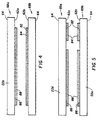
- the portion of disk 68b that is printed with data is combined with another one half of a disk 68a that carries the stored information to form the final CD.
- a dye layer 86 and a metallized reflective layer are coated on the internal surface 62a of the disk polymer support 22b for storing data.
- the printed colorant data in the disk record layer 20 and a back coat 84 are bonded to the internal surface 62b of the disk polymer support 22c.
- the back coat 84 which is coated over the polymeric receiver layer 20 is an acrylate-based polymer material containing TiO 2 particles.
- the whitening effect of the TiO 2 particles provides a background to the image in the polymer receiver layer 20. It is understood that coats of different colors can be coated in coat 84. It is also possible that no back coat is required, in that the polymeric binder for the dye receiving layer 20 can serve both to hold the dye image and to laminate the two portions of the disk together.
- the adhesives that are used in laminating the two portions of the disk are disclosed in the commonly assigned US-A-5,466,723; US-A-5,422,234; US-A-5,418,120; US-A-5,393,649; and US-A-5,340,420.
- FIG. 5 Another disk layout is illustrated in FIG. 5.
- the two portions of a disk 89a and 89b both carry the stored data and printed data on the internal surfaces 62c of the disk polymer supports 22d and 22e.
- dye layers 86 and metallized reflective layers are coated on the internal surfaces 62c of the disk polymer supports 22d and 22e for storing data.
- the printed colorant data in the disk record layer 20 and back coat 84 are bonded to the internal surfaces 62c of the disk polymer supports 22d and 22e.
- the two portions of disks 89a and 89b are combined to form the final CD.
- the adhesives are first applied on the inside surfaces of the two portions of the disk that are facing each other.
- the inside surfaces refer to the exposed portions of the surfaces on 62a, 62b, 62c, 84, and 88 in FIG. 4 and FIG. 5.
- the two portions of the disk are aligned and pressed together so that the inside surfaces are in good contact. Heating and other treatment can be applied to assist the curing of the adhesives.
- the final disk has the external surfaces of the polymer support 64 and the edges exposed to air.
- the adhesives and detailed lamination procedure are disclosed in the commonly assigned US-A-5,466,723; US-A-5,422,234; US-A-5,418,120; US-A-5,393,649; and US-A-5,340,420.
Landscapes
- Engineering & Computer Science (AREA)
- Manufacturing & Machinery (AREA)
- Optical Record Carriers And Manufacture Thereof (AREA)
- Magnetic Record Carriers (AREA)
Applications Claiming Priority (2)
| Application Number | Priority Date | Filing Date | Title |
|---|---|---|---|
| US80741097A | 1997-02-28 | 1997-02-28 | |
| US807410 | 1997-02-28 |
Publications (2)
| Publication Number | Publication Date |
|---|---|
| EP0863503A2 true EP0863503A2 (fr) | 1998-09-09 |
| EP0863503A3 EP0863503A3 (fr) | 2001-01-31 |
Family
ID=25196311
Family Applications (1)
| Application Number | Title | Priority Date | Filing Date |
|---|---|---|---|
| EP98200473A Withdrawn EP0863503A3 (fr) | 1997-02-28 | 1998-02-14 | Disque compact avec des informations perceptibles par l'oeil humain sur une surface intérieure |
Country Status (2)
| Country | Link |
|---|---|
| EP (1) | EP0863503A3 (fr) |
| JP (1) | JPH10308036A (fr) |
Cited By (4)
| Publication number | Priority date | Publication date | Assignee | Title |
|---|---|---|---|---|
| EP1229527A4 (fr) * | 1999-11-12 | 2005-05-11 | Matsushita Electric Industrial Co Ltd | Disque optique et appareil a disque optique |
| EP1431056A3 (fr) * | 2002-10-04 | 2005-07-06 | Fuji Photo Film Co., Ltd. | Support d'enregistrement optique |
| EP1515336A3 (fr) * | 2003-09-11 | 2007-09-12 | DOCdata Germany Berlin Optical Disc GmbH | Support d'information optique |
| WO2012066338A3 (fr) * | 2010-11-19 | 2012-08-09 | Lingvitae Holding As | Procédé et appareil pour l'écriture directe |
Families Citing this family (2)
| Publication number | Priority date | Publication date | Assignee | Title |
|---|---|---|---|---|
| JP2014028529A (ja) * | 2013-11-11 | 2014-02-13 | Seiko Epson Corp | データ記録媒体の表面層への印刷 |
| JP2015063144A (ja) * | 2015-01-13 | 2015-04-09 | セイコーエプソン株式会社 | データ記録媒体の表面層への印刷 |
Family Cites Families (4)
| Publication number | Priority date | Publication date | Assignee | Title |
|---|---|---|---|---|
| US4772582A (en) * | 1987-12-21 | 1988-09-20 | Eastman Kodak Company | Spacer bead layer for dye-donor element used in laser-induced thermal dye transfer |
| KR100272136B1 (ko) * | 1995-03-16 | 2000-11-15 | 오츠코츠 다케시 | 광학 디스크와 그 제조 방법 및 제조 장치 |
| JPH08315427A (ja) * | 1995-05-16 | 1996-11-29 | Dainippon Printing Co Ltd | 光ディスク |
| US5729533A (en) * | 1995-09-12 | 1998-03-17 | Wae Manufacturing Inc. | Two-sided, light-readable information recording disc stacks and methods of making same |
-
1998
- 1998-02-14 EP EP98200473A patent/EP0863503A3/fr not_active Withdrawn
- 1998-02-20 JP JP10039227A patent/JPH10308036A/ja active Pending
Cited By (5)
| Publication number | Priority date | Publication date | Assignee | Title |
|---|---|---|---|---|
| EP1229527A4 (fr) * | 1999-11-12 | 2005-05-11 | Matsushita Electric Industrial Co Ltd | Disque optique et appareil a disque optique |
| US7196975B1 (en) | 1999-11-12 | 2007-03-27 | Matsushita Electric Industrial Co., Ltd. | Magneto-optical disk with protective layer, and optical disk device |
| EP1431056A3 (fr) * | 2002-10-04 | 2005-07-06 | Fuji Photo Film Co., Ltd. | Support d'enregistrement optique |
| EP1515336A3 (fr) * | 2003-09-11 | 2007-09-12 | DOCdata Germany Berlin Optical Disc GmbH | Support d'information optique |
| WO2012066338A3 (fr) * | 2010-11-19 | 2012-08-09 | Lingvitae Holding As | Procédé et appareil pour l'écriture directe |
Also Published As
| Publication number | Publication date |
|---|---|
| JPH10308036A (ja) | 1998-11-17 |
| EP0863503A3 (fr) | 2001-01-31 |
Similar Documents
| Publication | Publication Date | Title |
|---|---|---|
| US5915858A (en) | Organizing pixels of different density levels for printing human readable information on CDs | |
| US5781221A (en) | Method of printing visually readable information on a compact disk | |
| US5894069A (en) | Transferring colorant from a donor element to a compact disc | |
| US5854175A (en) | Embossed compact disc surfaces for laser thermal labeling | |
| US7172991B2 (en) | Integrated CD/DVD recording and labeling | |
| US20040147399A1 (en) | Black leuco dyes for use in CD/DVD labeling | |
| US5797688A (en) | Thermal dye transfer printing of compact disc labels including a circular recessed carrier | |
| EP1509919B1 (fr) | Procede pour annoter des disques compacts et disque annote | |
| US6556234B1 (en) | Method for personalizing a data storage medium | |
| EP0863503A2 (fr) | Disque compact avec des informations perceptibles par l'oeil humain sur une surface intérieure | |
| US6983475B2 (en) | Method and data storage device that utilizes blocking material | |
| US20060204894A1 (en) | Optical recording medium and displaying method on surface of the medium | |
| JP2002197727A (ja) | 光ディスクの印刷方法及びその印刷方法による印刷を備えた光ディスク | |
| US7364780B2 (en) | Thermally-sensitive medium with Fabry-Perot cavities | |
| JP2000113516A (ja) | 光情報記録媒体 | |
| KR100688599B1 (ko) | 광디스크용 라벨 프린터를 구비한 광기록/재생 장치 및광디스크에 라벨을 인쇄하는 방법 | |
| JP4008832B2 (ja) | 光情報記録媒体 | |
| JPH11110816A (ja) | 光記録媒体及びイメージの形成方法 | |
| JP2001273687A (ja) | 光記録媒体の製造方法および識別情報記録方法 | |
| JP3383769B2 (ja) | 画像記録方法 | |
| JP2000071613A (ja) | 印刷媒体および印刷記録媒体 | |
| SE523048C2 (sv) | Skiva för lagring av digital och visuell information | |
| KR100618784B1 (ko) | 광디스크 및 이 광디스크용 라벨 프린팅 시스템 및 방법 | |
| JP3591430B2 (ja) | 光記録媒体 | |
| JP2006172588A (ja) | 光記録媒体 |
Legal Events
| Date | Code | Title | Description |
|---|---|---|---|
| PUAI | Public reference made under article 153(3) epc to a published international application that has entered the european phase |
Free format text: ORIGINAL CODE: 0009012 |
|
| AK | Designated contracting states |
Kind code of ref document: A2 Designated state(s): AT BE CH DE DK ES FI FR GB GR IE IT LI LU MC NL PT SE |
|
| AX | Request for extension of the european patent |
Free format text: AL;LT;LV;MK;RO;SI |
|
| PUAL | Search report despatched |
Free format text: ORIGINAL CODE: 0009013 |
|
| AK | Designated contracting states |
Kind code of ref document: A3 Designated state(s): AT BE CH DE DK ES FI FR GB GR IE IT LI LU MC NL PT SE |
|
| AX | Request for extension of the european patent |
Free format text: AL;LT;LV;MK;RO;SI |
|
| RIC1 | Information provided on ipc code assigned before grant |
Free format text: 7G 11B 7/24 A, 7G 11B 7/26 B, 7G 11B 23/40 B |
|
| STAA | Information on the status of an ep patent application or granted ep patent |
Free format text: STATUS: THE APPLICATION IS DEEMED TO BE WITHDRAWN |
|
| 18D | Application deemed to be withdrawn |
Effective date: 20000901 |