EP0863586B1 - Stütze für Leuchtstofflampe - Google Patents
Stütze für Leuchtstofflampe Download PDFInfo
- Publication number
- EP0863586B1 EP0863586B1 EP97103560A EP97103560A EP0863586B1 EP 0863586 B1 EP0863586 B1 EP 0863586B1 EP 97103560 A EP97103560 A EP 97103560A EP 97103560 A EP97103560 A EP 97103560A EP 0863586 B1 EP0863586 B1 EP 0863586B1
- Authority
- EP
- European Patent Office
- Prior art keywords
- lamp
- lamp assembly
- light fixture
- assembly
- upper cover
- Prior art date
- Legal status (The legal status is an assumption and is not a legal conclusion. Google has not performed a legal analysis and makes no representation as to the accuracy of the status listed.)
- Expired - Lifetime
Links
- 230000000712 assembly Effects 0.000 claims description 13
- 238000000429 assembly Methods 0.000 claims description 13
- 238000009434 installation Methods 0.000 claims description 7
- 230000008878 coupling Effects 0.000 claims description 5
- 238000010168 coupling process Methods 0.000 claims description 5
- 238000005859 coupling reaction Methods 0.000 claims description 5
- 238000003780 insertion Methods 0.000 claims description 3
- 230000037431 insertion Effects 0.000 claims description 3
- 238000005286 illumination Methods 0.000 description 5
- 238000010276 construction Methods 0.000 description 4
- 239000004033 plastic Substances 0.000 description 3
- 229920003023 plastic Polymers 0.000 description 3
- 238000012986 modification Methods 0.000 description 2
- 230000004048 modification Effects 0.000 description 2
- 238000005452 bending Methods 0.000 description 1
- 230000005540 biological transmission Effects 0.000 description 1
- 239000004020 conductor Substances 0.000 description 1
- 230000008602 contraction Effects 0.000 description 1
- 230000003247 decreasing effect Effects 0.000 description 1
- 230000007547 defect Effects 0.000 description 1
- 230000007257 malfunction Effects 0.000 description 1
- 239000000463 material Substances 0.000 description 1
- 230000013011 mating Effects 0.000 description 1
- 238000005192 partition Methods 0.000 description 1
- 239000002990 reinforced plastic Substances 0.000 description 1
- 230000002787 reinforcement Effects 0.000 description 1
- 230000000007 visual effect Effects 0.000 description 1
Images


Classifications
-
- H—ELECTRICITY
- H01—ELECTRIC ELEMENTS
- H01R—ELECTRICALLY-CONDUCTIVE CONNECTIONS; STRUCTURAL ASSOCIATIONS OF A PLURALITY OF MUTUALLY-INSULATED ELECTRICAL CONNECTING ELEMENTS; COUPLING DEVICES; CURRENT COLLECTORS
- H01R33/00—Coupling devices specially adapted for supporting apparatus and having one part acting as a holder providing support and electrical connection via a counterpart which is structurally associated with the apparatus, e.g. lamp holders; Separate parts thereof
- H01R33/05—Two-pole devices
- H01R33/06—Two-pole devices with two current-carrying pins, blades or analogous contacts, having their axes parallel to each other
- H01R33/08—Two-pole devices with two current-carrying pins, blades or analogous contacts, having their axes parallel to each other for supporting tubular fluorescent lamp
-
- F—MECHANICAL ENGINEERING; LIGHTING; HEATING; WEAPONS; BLASTING
- F21—LIGHTING
- F21S—NON-PORTABLE LIGHTING DEVICES; SYSTEMS THEREOF; VEHICLE LIGHTING DEVICES SPECIALLY ADAPTED FOR VEHICLE EXTERIORS
- F21S4/00—Lighting devices or systems using a string or strip of light sources
- F21S4/20—Lighting devices or systems using a string or strip of light sources with light sources held by or within elongate supports
-
- F—MECHANICAL ENGINEERING; LIGHTING; HEATING; WEAPONS; BLASTING
- F21—LIGHTING
- F21V—FUNCTIONAL FEATURES OR DETAILS OF LIGHTING DEVICES OR SYSTEMS THEREOF; STRUCTURAL COMBINATIONS OF LIGHTING DEVICES WITH OTHER ARTICLES, NOT OTHERWISE PROVIDED FOR
- F21V19/00—Fastening of light sources or lamp holders
- F21V19/0075—Fastening of light sources or lamp holders of tubular light sources, e.g. ring-shaped fluorescent light sources
- F21V19/008—Fastening of light sources or lamp holders of tubular light sources, e.g. ring-shaped fluorescent light sources of straight tubular light sources, e.g. straight fluorescent tubes, soffit lamps
-
- F—MECHANICAL ENGINEERING; LIGHTING; HEATING; WEAPONS; BLASTING
- F21—LIGHTING
- F21V—FUNCTIONAL FEATURES OR DETAILS OF LIGHTING DEVICES OR SYSTEMS THEREOF; STRUCTURAL COMBINATIONS OF LIGHTING DEVICES WITH OTHER ARTICLES, NOT OTHERWISE PROVIDED FOR
- F21V19/00—Fastening of light sources or lamp holders
- F21V19/04—Fastening of light sources or lamp holders with provision for changing light source, e.g. turret
-
- F—MECHANICAL ENGINEERING; LIGHTING; HEATING; WEAPONS; BLASTING
- F21—LIGHTING
- F21V—FUNCTIONAL FEATURES OR DETAILS OF LIGHTING DEVICES OR SYSTEMS THEREOF; STRUCTURAL COMBINATIONS OF LIGHTING DEVICES WITH OTHER ARTICLES, NOT OTHERWISE PROVIDED FOR
- F21V21/00—Supporting, suspending, or attaching arrangements for lighting devices; Hand grips
- F21V21/005—Supporting, suspending, or attaching arrangements for lighting devices; Hand grips for several lighting devices in an end-to-end arrangement, i.e. light tracks
-
- F—MECHANICAL ENGINEERING; LIGHTING; HEATING; WEAPONS; BLASTING
- F21—LIGHTING
- F21V—FUNCTIONAL FEATURES OR DETAILS OF LIGHTING DEVICES OR SYSTEMS THEREOF; STRUCTURAL COMBINATIONS OF LIGHTING DEVICES WITH OTHER ARTICLES, NOT OTHERWISE PROVIDED FOR
- F21V23/00—Arrangement of electric circuit elements in or on lighting devices
- F21V23/06—Arrangement of electric circuit elements in or on lighting devices the elements being coupling devices, e.g. connectors
Definitions
- the present invention relates to a small diameter fluorescent lamp, specifically, to a fluorescent lamp of a small diameter for ornamental purposes (to provide visual effects) as well as for simple illumination.
- the fluorescent lamp disclosed in U.S. Patent No. 5,521,805 has a construction where the fluorescent lamp is integral with a lamp assembly so that the lamp assembly as well as the fluorescent lamp must be replaced at the end of the lamp service life, or when the lamp fails.
- the fluorescent lamp has a construction which conveniently allows connecting multiple lamps in series by using female and male connectors made of plastic. This results in regular lamp spacing in applications using an array of multiple lamps. Therefore, the connecting portion which is apparently cut off does not present a fine exterior.
- a flourescent light fixture according to the precharacterized portion of claim 1 is known from US-A 5 226 724.
- a similar light fixture is known from US-A 5 124 896.
- the present invention is directed to a fluorescent lamp that substantially obviates one or more of the problems, limitations, and disadvantages of the related art.
- An objective of the present invention is to solve the above-mentioned problems and thus to create a fluorescent lamp with a construction amicable to convenient connecting and replacement of lamp assemblies, and possible replacement of fluorescent lamps only.
- a fluorescent light fixture including: a lamp assembly having a circuit board therein where various components for the lamp's operation are located; a lamp fixing member for fixing and connecting a lamp to the opposite ends of the lamp assembly by insertion into the fixing member; an upper cover covering the top surface of the lamp assembly; a connector connected to said lamp fixing member through an installation groove at one end of the lamp assembly; and a coupler coupling said connector to other similar connectors, characterised in that the lamp fixing member comprises a key slot, and a key for opening/closing the key slot so that the lamp can be removed from the lamp assembly through the key slot.
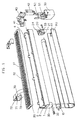
- the fluorescent lamp of the present invention basically has components that are similar to a conventional fluorescent lamp's. That is to say, the lamp comprises a lamp assembly 1 having a circuit board therein, a lamp fixing member 20, for fixing a lamp 10 to the opposite ends of the lamp assembly 1, and a lamp 10 inserted in the lamp fixing member 20 and illuminated when electrical power is supplied.
- the diameter of the lamp is smaller than that of a conventional lamp, the electronically fluorescent lamp generally has a compact construction, and all constituting elements are assembled.
- the small diameter fluorescent lamp may be used for ornamental purposes as well as simple illumination. This kind of lamp is applicable to furniture.
- An upper cover 30, is located over the lamp assembly having a circuit board (not shown), for opening/closing it.
- Multiple elastic hooks 4 protrude from the outer surface of the lamp assembly 1, mate with grooves 32 in the upper cover 30 to fasten the upper cover 30 to the lamp assembly 1.
- An installation groove 2, at one end of lamp assembly 1, is opened/closed by a stopper 3. Accordingly, when only one lamp assembly is used, the installation groove 2 is closed by the stopper 3, resulting in tidy exterior. Otherwise, when multiple lamp assemblies 1 are connected together, or when a plug for supplying electric power is connected, the stopper 3 is removed so that the installation groove 2 is a junction.
- a hook 24 protrudes from the top of the lamp fixing member 20, and is detachably coupled to a corresponding groove (not shown) in the lamp assembly.
- the lamp fixing member 20 contains a key slot 21 located at the lower portion thereof, and a key 22 inserted in the key slot.
- the fluorescent lamp is inserted/extracted into/out of the lamp assembly through key slot 21 after removing key 22.
- Key 22 closes key slot 21 after the fluorescent lamp 10 is inserted so that the fluorescent lamp is not extracted from the lamp assembly.
- Key 22 is essential for safety. Therefore, some countries require that the fluorescent lamp 10 not be extracted from the lamp assembly. In this regard, key 22 which seals the key slot, meets the above mentioned safety regulations.
- a fluorescent lamp cover 60 is installed at the outer portion of the lamp 10 for the purpose of reflection of fluorescent light or indirect illumination.
- a protruding portion 61 on the inner opposite ends of the fluorescent lamp cover 60 which is made of transparent or translucent plastic, mates with groove 23 on the outside of the lamp fixing member 20.
- bracket 70 is used to attach the lamp assembly 1 to a surface.
- brackets 70 are fastened at the location where the lamp assembly 1 should be installed, by inserting a screw through a hole 72, the lamp assembly 1 is pushed to the brackets 70 and held securely with hooks at the open ends of the channel shaped bracket 70.
- Hooks 73 at the open end of the channel shaped bracket 70 seize protruding ends of the upper cover 30 coupled to the lamp assembly 1.
- Long grooves 31 in the upper cover 30 add the reinforcement force with the corrugated surface formed by the long grooves 31 to the cover 30 in order to prevent the cover 30 from bending.
- a protrusion 71 on the upper inner surface of the bracket 70 moves along the long grooves 31 on the upper cover 30 until it stops at the ends of the cover 30, preventing the cover 30 from moving any further. Thereafter, lamp assembly 1 can be installed vertically without removing cover 30.
- connection between adjacent lamp assemblies is achieved with a connector 40 inserted into mating ends of the lamp assemblies and a coupler 50 coupling the connectors 40.
- Connector 40 which is inserted into the installation groove, contains a pair of electrical terminals 41, which make contact with the circuit board, (not shown) installed in the lamp assembly.
- a bent conductor 42 contacting opposite sides of the connector 40 connects the circuit board (not shown), and a terminal contact portion protruded downward is contacted with the end terminals of the lamp 10 by being inserted in the lamp fixing member 20.
- the connector 40 and the lamp assembly 1 are assembled with each other.
- the box-shaped coupler 50 which couples the connectors 40, contains a partition 51 installed in the center thereof, and U-shaped conductive clips 52 installed therein.
- the connector 40 is inserted through the clips 52 to electrically connect the connectors attached to the corresponding lamp assemblies, as shown in FIG. 2.
- Connectors 40 and the coupler 50, coupling connectors 40 are made of reinforced plastic, because these materials are not affected by heat, to prevent poor contact between the terminal members due to contraction or expansion of the terminal members.
- FIG. 3 shows the main bodies 1 of fluorescent lamps connected at a fixed interval.
- the electric power between the lamp assemblies can be connected by means of an electric wire 81, with a fixed length connected with connecting cable 80 inserted into one side of coupler 50.
- the fluorescent lamp can be installed perpendicularly or however desired.
- a plug 90 is installed at one end of the connecting cable 80 as shown in FIG. 4.
- the lamp can be turned on/off by a separate electric power switch installed on the electric wire 81.
- the fluorescent lamp can be replaced, and the lamp assembly is easily exchanged so that the lighting fixture can be used for a long time.
- the lamp assembly need not be replaced, thereby decreasing the cost.
- a lamp malfunctions only the lamp part of the lamp assembly of the lamp is replaced, it need not be disassembled and only one part thereof can be easily replaced.
- the present invention provides a convenient connection between the connecting member, and no poor operation resulting from the transmission of heat.
Landscapes
- Engineering & Computer Science (AREA)
- General Engineering & Computer Science (AREA)
- Arrangement Of Elements, Cooling, Sealing, Or The Like Of Lighting Devices (AREA)
- Non-Portable Lighting Devices Or Systems Thereof (AREA)
- Fastening Of Light Sources Or Lamp Holders (AREA)
Claims (8)
- Leuchtstofflampenkörper, umfassend: eine Lampeneinheit (1), welche darin eine Leiterplatte aufweist, auf der sich unterschiedliche Komponenten zum Betrieb der Lampe befinden; ein Lampen-Befestigungsteil (20) zum Befestigen und Kontaktieren einer Lampe (10) an den entgegengesetzten Enden der Lampeneinheit (1) durch Einsetzen in das Befestigungsteil (20); eine obere Abdeckung (30), welche die obere Außenfläche der Lampeneinheit (1) abdeckt; einen Verbinder (40), welcher mit dem Lampen-Befestigungsteil (20) über eine Installationsaussparung (2) an einem Ende der Lampeneinheit (1) verbunden ist; und einen Koppler (50), welcher den Verbinder (40) mit anderen ähnlichen Verbindern koppelt, dadurch gekennzeichnet, daß das Lampen-Befestigungsteil (20) einen Schlüsselschlitz und einen Schlüssel zum Öffnen/Schließen des Schlüsselschlitzes (21) aufweist, so daß die Lampe (10) durch den Schlüsselschlitz (21) von der Lampeneinheit (1) entfernt werden kann.
- Lampenkörper nach Anspruch 1, bei welchem eine transparente oder durchscheinende Leuchtstofflampenabdeckung (60) zusätzlich an der Lampeneinheit (1) angebracht ist, in welche die Lampe (10) eingesetzt wird.
- Lampenkörper nach Anspruch 1 oder 2, bei welcher ein Paar von kanalförmigen Klammern (70) elastisch auf der oberen Abdeckung (30) eingehakt sind, um die Lampeneinheit (1) an einer ebenen Oberfläche anzubringen.
- Lampenkörper nach Anspruch 3, bei welcher mehrere lange Aussparungen (31) in der oberen Abdeckung (30) mit Vorsprüngen (71) an den Befestigungsklammern (70) zusammenpassen, so daß die Lampeneinheit (1) nicht aus der Befestigungsklammer (70) herausgleitet.
- Lampenkörper nach einem der Ansprüche 1 bis 4, bei welcher, wenn die Lampeneinheiten (1) nicht miteinander verbunden werden, kein Verbinder (40) installiert ist, und anstelle dessen eine Blende in einer Installationsaussparung (2) in der Lampeneinheit (1) eingepaßt ist, um das offene Ende der Lampeneinheit (1) abzuschließen.
- Lampenkörper nach einem der Ansprüche 1 bis 5, bei welcher elektrische Energie über ein in eine Seite des Kopplers (50) eingestecktes Verbindungskabel (80) und einen damit verbundenen Stecker (90) zugeführt wird.
- Lampenkörper nach Anspruch 6, wobei zwei Lampeneinheiten (1) in einem festen Abstand mit einem Verbindungskabel (80, 81) verbunden sind, wobei an einem Ende anstelle eines Steckers ein Verbinder die Verbindung zur zweiten Lampeneinheit herstellt.
- Lampenkörper nach einem der Ansprüche 1 bis 7, bei welcher mehrere elastische Haken (4) über dem oberen Abschnitt der Lampeneinheit (1) hervorstehen und in Einsetz-Aussparungen (32) der oberen Abdeckung (30) eingesetzt sind, um die obere Abdeckung (30) zu befestigen.
Priority Applications (5)
| Application Number | Priority Date | Filing Date | Title |
|---|---|---|---|
| US08/801,404 US5906427A (en) | 1997-02-20 | 1997-02-20 | Fluorescent lamp |
| EP97103560A EP0863586B1 (de) | 1997-02-20 | 1997-03-04 | Stütze für Leuchtstofflampe |
| DE69723048T DE69723048T2 (de) | 1997-03-04 | 1997-03-04 | Stütze für Leuchtstofflampe |
| CN97104559A CN1090808C (zh) | 1997-02-20 | 1997-03-25 | 荧光灯固定装置 |
| JP9102436A JPH10283808A (ja) | 1997-02-20 | 1997-04-07 | 蛍光ランプ |
Applications Claiming Priority (4)
| Application Number | Priority Date | Filing Date | Title |
|---|---|---|---|
| US08/801,404 US5906427A (en) | 1997-02-20 | 1997-02-20 | Fluorescent lamp |
| EP97103560A EP0863586B1 (de) | 1997-02-20 | 1997-03-04 | Stütze für Leuchtstofflampe |
| CN97104559A CN1090808C (zh) | 1997-02-20 | 1997-03-25 | 荧光灯固定装置 |
| JP9102436A JPH10283808A (ja) | 1997-02-20 | 1997-04-07 | 蛍光ランプ |
Publications (2)
| Publication Number | Publication Date |
|---|---|
| EP0863586A1 EP0863586A1 (de) | 1998-09-09 |
| EP0863586B1 true EP0863586B1 (de) | 2003-06-25 |
Family
ID=27429995
Family Applications (1)
| Application Number | Title | Priority Date | Filing Date |
|---|---|---|---|
| EP97103560A Expired - Lifetime EP0863586B1 (de) | 1997-02-20 | 1997-03-04 | Stütze für Leuchtstofflampe |
Country Status (4)
| Country | Link |
|---|---|
| US (1) | US5906427A (de) |
| EP (1) | EP0863586B1 (de) |
| JP (1) | JPH10283808A (de) |
| CN (1) | CN1090808C (de) |
Families Citing this family (34)
| Publication number | Priority date | Publication date | Assignee | Title |
|---|---|---|---|---|
| US6793381B2 (en) * | 1996-04-10 | 2004-09-21 | Bji Energy Solutions, Llc | CCFL illuminated device and method of use |
| US6152573A (en) * | 1998-08-05 | 2000-11-28 | Mitchell; Cary L. | Lens retainer for lighted sign |
| USD424230S (en) * | 1998-10-23 | 2000-05-02 | Boam R&D Co., Ltd. | Fluorescent lamp |
| GB9823482D0 (en) * | 1998-10-28 | 1998-12-23 | Hopper John D | Lighting apparatus |
| DE19911377B4 (de) * | 1999-03-15 | 2004-02-19 | NORKA Norddeutsche Kunststoff- und Elektro-Gesellschaft Stäcker & Co. mbH | Leuchte für langgestreckte Lampen und Verfahren zur Montage von langgestreckten Lampen |
| US6530673B1 (en) * | 1999-03-24 | 2003-03-11 | Japan Servo Co., Ltd. | Lighting fixture mounting device and lamp protecting device |
| US6511213B1 (en) * | 2000-11-14 | 2003-01-28 | Techlite Inc. | Lighting fixture lens retainer |
| USD473670S1 (en) | 2001-02-23 | 2003-04-22 | Victor Kelmelis | Interspaced flush lighting assembly |
| USD496487S1 (en) | 2003-07-31 | 2004-09-21 | Thin-Lite Corporation | Combination light fixture and lens assembly |
| USD514248S1 (en) | 2003-07-31 | 2006-01-31 | Thin-Lite Corporation | Light fixture frame |
| US6929389B1 (en) | 2003-07-31 | 2005-08-16 | Thin-Lite Corporation | Lighting fixture frame and mounting panel apparatus |
| CN1715737B (zh) * | 2004-06-29 | 2010-12-08 | 威海碧陆斯电子有限公司 | 荧光灯器具以及荧光灯插座 |
| JP2006344602A (ja) * | 2005-06-09 | 2006-12-21 | Samsung Electronics Co Ltd | ランプ、ランプホルダー、電源供給モジュール、それを有するバックライトアセンブリ及び表示装置 |
| TWM279082U (en) * | 2005-06-14 | 2005-10-21 | Omnilux Lighting Llc | Connection device for lamps |
| US7293895B2 (en) * | 2005-10-20 | 2007-11-13 | Cathode Lighting Systems, Inc. | Modular lighting system and method of installation |
| USD564694S1 (en) | 2006-02-17 | 2008-03-18 | Liteco | Light fixture |
| US20080165530A1 (en) * | 2007-01-10 | 2008-07-10 | Westerveld Johannes Hendrikus | Illuminative apparatus |
| USD593698S1 (en) * | 2007-05-15 | 2009-06-02 | Averd Co., Ltd. | Fluorescent lamp fixture |
| USD595444S1 (en) * | 2007-08-01 | 2009-06-30 | Sanyo Electric Co., Ltd. | LED lamp |
| WO2009019946A1 (ja) * | 2007-08-09 | 2009-02-12 | Nec Lighting, Ltd. | 照明装置および、該照明装置を複数備えた照明ユニット |
| USD608928S1 (en) * | 2008-01-31 | 2010-01-26 | Si Chung Noh | Fluorescent lamp fixture |
| US20090196029A1 (en) * | 2008-02-05 | 2009-08-06 | Richard Kurtz | Discharge lamp and fixture therefor |
| DE202008014905U1 (de) * | 2008-04-01 | 2009-08-13 | Zumtobel Lighting Gmbh | Lichtbandsystem |
| USD612978S1 (en) * | 2008-10-28 | 2010-03-30 | DTT Group LLC | Lamp base unit |
| USD620189S1 (en) | 2009-05-22 | 2010-07-20 | Coleman Hill | Protective casing for exterior lighting fixtures |
| US8454192B2 (en) * | 2009-06-05 | 2013-06-04 | Abl Ip Holding Llc | Strip lighting fixture with channel |
| US8764220B2 (en) * | 2010-04-28 | 2014-07-01 | Cooper Technologies Company | Linear LED light module |
| WO2011139764A2 (en) | 2010-04-27 | 2011-11-10 | Cooper Technologies Company | Linkable linear light emitting diode system |
| CN102338320B (zh) * | 2010-07-29 | 2013-10-09 | 富士迈半导体精密工业(上海)有限公司 | 灯条组件及灯条固定装置 |
| US8960962B2 (en) | 2012-10-01 | 2015-02-24 | Abl Ip Holding Llc | Ceiling mount fixture |
| US20140168975A1 (en) * | 2012-12-14 | 2014-06-19 | Avago Technologies General Ip (Singapore) Pte. Ltd | Lighting fixture with flexible lens sheet |
| US9080731B2 (en) * | 2013-11-04 | 2015-07-14 | Luminator Holding, Lp | Lighting housing with LED illumination insert |
| JP2021176119A (ja) * | 2020-05-01 | 2021-11-04 | 有限会社カナリヤ総合システム | 易設蛍光灯器具 |
| US12098828B1 (en) * | 2023-05-02 | 2024-09-24 | Elemental LED, Inc. | Rotating bracket for linear lighting |
Family Cites Families (17)
| Publication number | Priority date | Publication date | Assignee | Title |
|---|---|---|---|---|
| US3086105A (en) * | 1960-01-27 | 1963-04-16 | Westinghouse Electric Corp | Luminaire |
| US3120929A (en) * | 1960-03-31 | 1964-02-11 | Curtis Electro Lighting Inc | Fluorescent lighting fixture |
| US3375322A (en) * | 1963-09-23 | 1968-03-26 | Thomas Industries Inc | Power unit assembly for fluorescent lighting system |
| US3299264A (en) * | 1964-08-28 | 1967-01-17 | Willis L Lipscomb | End plate for lighting fixtures |
| US3349237A (en) * | 1964-12-29 | 1967-10-24 | Sylvania Electric Prod | Strip lighting fixture and connector therefor |
| US3892457A (en) * | 1973-12-04 | 1975-07-01 | Lewis Detch | Locking means for double pin fluorescent lamps |
| US4494175A (en) * | 1984-01-09 | 1985-01-15 | Gte Products Corporation | Recessed lighting fixture with improved louver mounting |
| DE3634955A1 (de) * | 1986-10-14 | 1988-04-21 | Grigull Karl August | Anordnung fuer den betrieb mehrerer leuchtstoffroehren |
| US4726781A (en) * | 1987-05-05 | 1988-02-23 | Lightolier Incorporated | Connective mechanism for adjacent fluorescent fixtures |
| JPH03190007A (ja) * | 1989-12-19 | 1991-08-20 | Tokyo Electric Co Ltd | 照明器具 |
| US5088015A (en) * | 1991-06-26 | 1992-02-11 | Woodhead Industries, Inc. | Portable fluorescent lamp fixture |
| US5124896A (en) * | 1991-09-04 | 1992-06-23 | Bentley Raymond B | Fluorescent lamp fixture |
| US5226724A (en) * | 1992-06-17 | 1993-07-13 | Kanarek Shepard S | Modular, user-installed, surface-mounted, fluorescent lighting system |
| JPH06215609A (ja) * | 1993-01-13 | 1994-08-05 | Hitachi Lighting Ltd | チェン吊り蛍光灯器具のルーバ取付構造 |
| US5521805A (en) * | 1993-08-05 | 1996-05-28 | Lim; Young G. | Fluorescent lamp |
| US5410462A (en) * | 1993-11-18 | 1995-04-25 | Usi Lighting, Inc. | Modular recessed compact fluorescent lamp fixture |
| US5448460A (en) * | 1994-05-05 | 1995-09-05 | Lighting World Inc. | Fluorescent lighting fixture having a bendable support and mounting system |
-
1997
- 1997-02-20 US US08/801,404 patent/US5906427A/en not_active Expired - Fee Related
- 1997-03-04 EP EP97103560A patent/EP0863586B1/de not_active Expired - Lifetime
- 1997-03-25 CN CN97104559A patent/CN1090808C/zh not_active Expired - Fee Related
- 1997-04-07 JP JP9102436A patent/JPH10283808A/ja active Pending
Also Published As
| Publication number | Publication date |
|---|---|
| CN1090808C (zh) | 2002-09-11 |
| US5906427A (en) | 1999-05-25 |
| CN1194451A (zh) | 1998-09-30 |
| JPH10283808A (ja) | 1998-10-23 |
| EP0863586A1 (de) | 1998-09-09 |
Similar Documents
| Publication | Publication Date | Title |
|---|---|---|
| US5906427A (en) | Fluorescent lamp | |
| US5658067A (en) | Modular light unit | |
| US8079739B2 (en) | Interlocking system for hanging decorative lights and fixtures | |
| KR102044663B1 (ko) | 레일조명시스템용 led조명등 | |
| KR102292015B1 (ko) | 간편 장착 및 전원 연결구조를 갖는 레일조명 | |
| US7314295B2 (en) | Ceiling light with an oblong light housing | |
| KR100274271B1 (ko) | 조광기 | |
| US20020008975A1 (en) | Lighting fixture mounting device and lamp protecting device | |
| KR102159999B1 (ko) | 레일 등기구 조립구조 | |
| US6048220A (en) | Lampholder connector for multiple fluorescent lamps | |
| US4929192A (en) | Connection and fixing system for electronic unit | |
| CN216346150U (zh) | 一种拔插式更换的控制装置及其应用的灯具 | |
| CN211289977U (zh) | 一种组装式灯具 | |
| CN104879715A (zh) | 一种条形灯 | |
| KR19980067484A (ko) | 형광 램프 | |
| US5615942A (en) | Light socket adapter | |
| CN223954017U (zh) | 灯具的拼接结构 | |
| KR102918055B1 (ko) | Led 매입등 | |
| CN222378029U (zh) | 一种灯具插拔接头 | |
| KR200298563Y1 (ko) | 형광램프의 소켓구조 | |
| KR20240148596A (ko) | 천장직착등 조립체 | |
| KR0121632Y1 (ko) | 연속취부형 조명기구 | |
| KR200412939Y1 (ko) | 조명기기의 전원공급용 커넥터 | |
| KR200285370Y1 (ko) | 형광등용 소켓 | |
| KR200203500Y1 (ko) | 형광등용 소켓 지지구조 |
Legal Events
| Date | Code | Title | Description |
|---|---|---|---|
| PUAI | Public reference made under article 153(3) epc to a published international application that has entered the european phase |
Free format text: ORIGINAL CODE: 0009012 |
|
| AK | Designated contracting states |
Kind code of ref document: A1 Designated state(s): DE FR GB IT |
|
| AX | Request for extension of the european patent |
Free format text: AL;LT;LV;SI |
|
| 17P | Request for examination filed |
Effective date: 19980901 |
|
| AKX | Designation fees paid |
Free format text: DE FR GB IT |
|
| RBV | Designated contracting states (corrected) |
Designated state(s): DE FR GB IT |
|
| 17Q | First examination report despatched |
Effective date: 19990506 |
|
| RTI1 | Title (correction) |
Free format text: SUPPORT FOR FLUORESCENT LAMP |
|
| GRAH | Despatch of communication of intention to grant a patent |
Free format text: ORIGINAL CODE: EPIDOS IGRA |
|
| GRAH | Despatch of communication of intention to grant a patent |
Free format text: ORIGINAL CODE: EPIDOS IGRA |
|
| GRAA | (expected) grant |
Free format text: ORIGINAL CODE: 0009210 |
|
| AK | Designated contracting states |
Designated state(s): DE FR GB IT |
|
| REG | Reference to a national code |
Ref country code: GB Ref legal event code: FG4D |
|
| REF | Corresponds to: |
Ref document number: 69723048 Country of ref document: DE Date of ref document: 20030731 Kind code of ref document: P |
|
| PLBE | No opposition filed within time limit |
Free format text: ORIGINAL CODE: 0009261 |
|
| STAA | Information on the status of an ep patent application or granted ep patent |
Free format text: STATUS: NO OPPOSITION FILED WITHIN TIME LIMIT |
|
| ET | Fr: translation filed | ||
| 26N | No opposition filed |
Effective date: 20040326 |
|
| PGFP | Annual fee paid to national office [announced via postgrant information from national office to epo] |
Ref country code: GB Payment date: 20050307 Year of fee payment: 9 |
|
| PGFP | Annual fee paid to national office [announced via postgrant information from national office to epo] |
Ref country code: DE Payment date: 20050309 Year of fee payment: 9 |
|
| PGFP | Annual fee paid to national office [announced via postgrant information from national office to epo] |
Ref country code: FR Payment date: 20050311 Year of fee payment: 9 |
|
| PG25 | Lapsed in a contracting state [announced via postgrant information from national office to epo] |
Ref country code: GB Free format text: LAPSE BECAUSE OF NON-PAYMENT OF DUE FEES Effective date: 20060304 |
|
| PGFP | Annual fee paid to national office [announced via postgrant information from national office to epo] |
Ref country code: IT Payment date: 20060331 Year of fee payment: 10 |
|
| PG25 | Lapsed in a contracting state [announced via postgrant information from national office to epo] |
Ref country code: DE Free format text: LAPSE BECAUSE OF NON-PAYMENT OF DUE FEES Effective date: 20061003 |
|
| GBPC | Gb: european patent ceased through non-payment of renewal fee |
Effective date: 20060304 |
|
| REG | Reference to a national code |
Ref country code: FR Ref legal event code: ST Effective date: 20061130 |
|
| PG25 | Lapsed in a contracting state [announced via postgrant information from national office to epo] |
Ref country code: FR Free format text: LAPSE BECAUSE OF NON-PAYMENT OF DUE FEES Effective date: 20060331 |
|
| PG25 | Lapsed in a contracting state [announced via postgrant information from national office to epo] |
Ref country code: IT Free format text: LAPSE BECAUSE OF NON-PAYMENT OF DUE FEES Effective date: 20070304 |