EP0863634B1 - Réseau de transmission en anneau reconfigurable avec multiplexage en longueur d'onde pour liaisons semi-permanentes - Google Patents
Réseau de transmission en anneau reconfigurable avec multiplexage en longueur d'onde pour liaisons semi-permanentes Download PDFInfo
- Publication number
- EP0863634B1 EP0863634B1 EP98400329A EP98400329A EP0863634B1 EP 0863634 B1 EP0863634 B1 EP 0863634B1 EP 98400329 A EP98400329 A EP 98400329A EP 98400329 A EP98400329 A EP 98400329A EP 0863634 B1 EP0863634 B1 EP 0863634B1
- Authority
- EP
- European Patent Office
- Prior art keywords
- network
- optical
- transmission
- ring
- site
- Prior art date
- Legal status (The legal status is an assumption and is not a legal conclusion. Google has not performed a legal analysis and makes no representation as to the accuracy of the status listed.)
- Expired - Lifetime
Links
- 230000003287 optical effect Effects 0.000 title claims description 55
- 230000005540 biological transmission Effects 0.000 title claims description 22
- 239000013307 optical fiber Substances 0.000 claims description 17
- 230000001360 synchronised effect Effects 0.000 claims description 5
- 238000000605 extraction Methods 0.000 description 29
- 239000000835 fiber Substances 0.000 description 24
- 238000004891 communication Methods 0.000 description 6
- 238000000034 method Methods 0.000 description 4
- 238000003780 insertion Methods 0.000 description 3
- 230000037431 insertion Effects 0.000 description 3
- 230000003595 spectral effect Effects 0.000 description 2
- 238000011144 upstream manufacturing Methods 0.000 description 2
- 229910013641 LiNbO 3 Inorganic materials 0.000 description 1
- 238000007792 addition Methods 0.000 description 1
- 230000007613 environmental effect Effects 0.000 description 1
- 239000000543 intermediate Substances 0.000 description 1
- 230000001902 propagating effect Effects 0.000 description 1
- 230000006641 stabilisation Effects 0.000 description 1
- 238000011105 stabilization Methods 0.000 description 1
Images



Classifications
-
- H—ELECTRICITY
- H04—ELECTRIC COMMUNICATION TECHNIQUE
- H04J—MULTIPLEX COMMUNICATION
- H04J14/00—Optical multiplex systems
- H04J14/02—Wavelength-division multiplex systems
- H04J14/0278—WDM optical network architectures
- H04J14/0283—WDM ring architectures
-
- H—ELECTRICITY
- H04—ELECTRIC COMMUNICATION TECHNIQUE
- H04J—MULTIPLEX COMMUNICATION
- H04J14/00—Optical multiplex systems
- H04J14/02—Wavelength-division multiplex systems
- H04J14/0227—Operation, administration, maintenance or provisioning [OAMP] of WDM networks, e.g. media access, routing or wavelength allocation
-
- H—ELECTRICITY
- H04—ELECTRIC COMMUNICATION TECHNIQUE
- H04J—MULTIPLEX COMMUNICATION
- H04J14/00—Optical multiplex systems
- H04J14/02—Wavelength-division multiplex systems
- H04J14/0227—Operation, administration, maintenance or provisioning [OAMP] of WDM networks, e.g. media access, routing or wavelength allocation
- H04J14/0241—Wavelength allocation for communications one-to-one, e.g. unicasting wavelengths
-
- H—ELECTRICITY
- H04—ELECTRIC COMMUNICATION TECHNIQUE
- H04J—MULTIPLEX COMMUNICATION
- H04J14/00—Optical multiplex systems
- H04J14/02—Wavelength-division multiplex systems
- H04J14/0278—WDM optical network architectures
- H04J14/0286—WDM hierarchical architectures
-
- H—ELECTRICITY
- H04—ELECTRIC COMMUNICATION TECHNIQUE
- H04Q—SELECTING
- H04Q11/00—Selecting arrangements for multiplex systems
- H04Q11/0001—Selecting arrangements for multiplex systems using optical switching
Definitions
- the present invention relates to a network of reconfigurable transmission for semi-permanent links or, more generally, temporary.
- Known networks which realize temporary links between two users, are founded on a star architecture and multiplexing in wave length.
- the resources of a network of this type are pooled by an optical coupler.
- Each station in the network is equipped with a tunable optical filter that selects the length waveform serving as a support for transmitting information.
- Network management and implementation communication are managed by a data network that is superimposed on the star network.
- two optical fibers ensure the transmission of information between the coupler optical, which can be single or multiple, and a station.
- the station is then isolated from the rest of the network.
- Synchronous Digital Hierarchy ( Synchronous Digital Hierarchy” or “SDH”)
- SDH Synchronous Digital Hierarchy
- Reconfigurable architectures known are based on spectral routing and use tunable optical filters.
- the first category includes filters Fabry-Perot bundles and made with the techniques of micro-optics.
- the corresponding insertion losses are about 2 dB and the fineness is between 100 and 200.
- the insertion-extraction function (" add-drop ”) is obtained with an optical coupler.
- the second category consists of the acousto-optical modulator realized in integrated optics on LiNbO 3 .
- This modulator has the function directly insertion-extraction and its domain of tunability is about 100 nm.
- Such modulators are still at the stage of the laboratory and are penalized by a high level of crosstalk (from 15 to 18 dB), which limits their application at great distances between channels (greater than 4 nm) and makes critical the reuse of wavelengths.
- modulators have a coefficient high temperature (of the order of 0.1 nm / ° C) and therefore require temperature stabilization so that their operation is stable.
- the present invention aims to to overcome the previous disadvantages related to the use of tunable filters.
- the invention uses the spectral routing on a ring network, with fixed optical filters and optical switches intended to establish links between stations or network users.
- each node comprises a insertion-extraction multiplexer which is intended to exchange form information optical with the corresponding site and by through which the means of management control the optical switching means of this node.
- the ring is connected to a main transmission network information, at least one insertion-extraction multiplexer installed on this network transmission of information, provided with wavelength transmission-reception means particular and connected to the ring via insertion-extraction means at wavelength special.
- the network comprises a plurality of rings connected to a main transmission network information, a plurality of multiplexers electronic insertion-extraction being installed on this main network of information transmission and respectively associated with the rings, each insertion-extraction multiplexer being equipped with transmission-reception means to the length particular wave and connected to the corresponding ring through means of insertion-extraction the particular wavelength.
- At least one site may include N users respectively associated with N means of transmission-reception in this site, N being an integer at least equal to 2, the node corresponding to this site further comprising N type 1 to N optical switches that are controlled by the network management means of in order to be able to create an optical link to the particular wavelength between any of the users of this site and a user of another site.
- the network comprises two ring optical fibers that are meant to be traveled in opposite directions by the information.
- the optical switching means capable of to be in the first and second states can be cross-bar type switches.
- the information under optical form have a wavelength equal to 1.3 ⁇ m and the particular wavelength is equal to 1.5 microns.
- Each site can include means transmission-reception at a plurality of lengths particular wave, which are respectively associated to a plurality of insertion-extraction means optical at these particular wavelengths, in order to be able simultaneously to establish a plurality temporary optical links.
- each ring is designed to use the standard Synchronous Digital Hierarchy.
- insertion-extraction multiplexers electronic or MIE add-drop multiplexers
- ADM add-drop multiplexers
- This network 2 comprises two optical fibers 2a and 2b which are traversed in opposite directions by information in optical form and that pass successively by the nodes of the network 2.
- main node and in which is a MIE 6.
- This MIE 6 is linked to management means network 8.
- FIG. 1 another ring-shaped network 10 which includes several nodes 12, three nodes in the example shown.
- the network 10 also includes another MIE 14 which is linked to the MIE 4.
- Each of the nodes 12 is associated with a site 13 which corresponds to a user equipped with equipment 15.
- This equipment is a MIE or preferably, a terminal multiplexer.
- each node 12 contains a MIE 16 which is intended to exchange information in form optical with the equipment 15 that is in the site 13 associated with this node.
- the nodes 12 and the MIE 14 are connected to each other by an optical fiber 18 called normal fiber that forms a loop in which information flows in a sense determined since the MIE 14 passing successively by the nodes 12 to return to this MIE 14.
- backup fiber also forms a loop in which information flows in the opposite direction to the previous since the MIE 14 by the way successively by the nodes 12 to return to this MIE 14.
- the network 10 is a standard HNS ring unidirectional to MIE that uses only one optical wavelength ⁇ , for example equal to 1.3 ⁇ m, for the circulation of information on fibers 18 and 20.
- the present invention modifies the network shown in Figure 1 in order to establish temporary optical links between users of the network, two users at a time, one wavelength ⁇ c (different from ⁇ ), in addition to already existing links at the wavelength ⁇ .
- the links at the wavelength ⁇ c are reconfigurable and multiplexing of wavelengths ⁇ and ⁇ c.
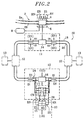
- the ring 10 of Figure 2 includes a normal optical fiber 18 and an optical fiber of 20, the added resources 22, 24 and 26 are doubles.
- the means 22 comprise, for the fiber 18 (respectively fiber 20), an EN transmitter and a RN receiver (respectively an ES transmitter and a RS receiver).
- the means 24 comprise, for the fiber 10 (respectively fiber 20), means XN (respectively XS) to extract the signals wavelength ⁇ c propagating in this fiber and IN means (respectively IS) for inserting signals of wavelength ⁇ c among the signals which circulate in this fiber.
- the means XN and XS are mounted upstream of the MIE 16 while the means IN and IS are mounted downstream of this MIE 16.
- Means 26 include a switch CN optics associated with fiber 18 and a switch CS optics associated with the fiber 20.
- Each of these CN and CS optical switches is able to be in two distinct states.
- switches are used optical cross-bar type.
- the management means 8 send control signals to the CN and CS switches by intermediates of MIE 6, MIE 14, fibers 18 and 20 and MIE 16.
- each of these CN and CS switches have four terminals a, b, c and d.
- the terminals have CN and CS switches are respectively connected to the means XN and XS.
- the terminals b of the CN and CS switches are respectively connected to the means IN and IS.
- the c terminals of the CN and CS switches are respectively connected to the receivers RN and RS.
- the d terminals of the CN and CS switches are respectively connected to transmitters EN and ES.
- transmitters corresponding respectively to the fibers 10 and 20 have again the respective references EN and ES.
- XN, IN, XS and IS are respectively connected to the receiver RN, the transmitter EN, to the RS receiver and the MIE 6 ES transmitter as it is see figure 2.
- each of the means XN and XS is upstream of the MIE 14 while each means IN and IS is mounted downstream of this MIE 14.
- each of transmitters EN and ES at the wavelength ⁇ c, of which is equipped with MIE 6, is intended to send information to this wavelength ⁇ c to the users of the ring 10.
- each of the RN and RS receivers at the wavelength ⁇ c, of which this MIE 6 is equipped, is intended to detect information at this length wavelength ⁇ c from these users.
- Figure 3 schematically illustrates the configuration of a node 12 at rest.
- each of the switches CN and CS optics of this node 12 is in the state "Bar" and the equipment 15 of the user associated with this node is disconnected from ring 10.
- FIG. 4 schematically illustrates the opposite configuration of this node 12.
- the equipment of the user associated with the node 12 is, on the contrary, connected to the ring 10.
- cross-bar switches are controlled by signals of wavelength ⁇ through the associated MIE 16.
- the equipment 15 of each user is by example a MIE STM-1 or preferably a terminal multiplexer receiving an STM-1 bit rate with a Useful digital load (2, 8, 34 or 140 Mbit / s) or ATM.
- wavelengths ⁇ and ⁇ c are for example respectively equal to 1.3 microns and 1.5 microns.
- the cross-bar optical switches are ordered by the network operator from the supervision of the ring for example through the inputs and environmental outputs that equip the MIE used for the HNS.
- An environment entry is used to check the activated state of the switch before give the users agreement to establish a communication.
- the means of insertion and extraction at the wavelength ⁇ c are commercially available from ATI companies, JDS, E-Tek and Dicon with a loss of less than 1.5 dB.
- Cross-bar optical switches used are available from the same companies with a loss of less than 1 dB.
- the network according to the invention diagrammatically shown in FIG. to put, on demand, two users in communication with each other.
- the network manager checks first the availability of this recipient then gives his agreement for setting in communication and control the optical switches of the corresponding nodes.
- the link is then established between two users from two different nodes and the information can be exchanged at the wavelength ⁇ c
- Ring 10 is available again for establish other temporary links at length ⁇ c wave between other users.
- Figure 5 is a schematic view of a other particular embodiment of the object network of the invention.
- the network not only includes the ring 10 of Figure 2, which is connected to the main network 2 via the main node 4 of this network 2 but still one or several other rings such as ring 10a which is connected to another main node 4a of the network 2.
- Node 4a is made up of the same way that the node 4, with a MIE that one has provided transmission-reception means at the wavelength ⁇ c (not shown)
- the ring 10a is also identical to the ring 10, the references of the components of this ring 10a being the same as those of the components counterparts of ring 10 but followed by letter a.
- reference 11 corresponds to the assembly comprising the MIE 14 and the means XN, EN, IS and RS of Figure 2.
- the network of Figure 5 makes it possible to establish a temporary connection between two users respectively connected to the rings 10 and 10a by through the network 2.
- this network 2 (which, in the case Figures 2 and 5, is also a ring), the information exchanged are treated as if they came from users connected to ring 10.
- the exchanged debit may belong to the digital domain of the Digital Hierarchy Plesiochronous (2, 8 or 34 Mbit / s) or can match Asynchronous Transfer Mode.
- Figure 6 is a schematic view and of another network according to the invention in which a site or a plurality of sites of the ring 10 of Figure 2, for example all of these sites, no longer includes a single user but N users, N being an integer at least 2.
- This number N is equal to 4 in the example shown in Figure 6.
- Each of these equipments is itself equipped transmission-reception means 22 at the wavelength ⁇ c which are mentioned in the description of the figure 2.
- the corresponding node 12 includes, in addition insertion-extraction means IN, XN, IS, XS and CN switches, CS mentioned in the description of FIG. 2, four type 1 optical switches to 4 which are also ordered by the means of management of the network (Figure 2) through the MIE 16 of the considered node and are referenced C1, C2, C3 and C4.
- the set of CN and CS switches and switches C1, C2, C3 and C4 form the means of switching 26 in the case of Figure 6.
- Each of these optical switches of the type 1 to 4 is able to be in four states different: under the control of the management means 8, its entry E is likely to be connected to that of its four S outputs that has been chosen.
- terminals c and d of the switch CN are respectively connected to the inputs of switches C1 and C2 while the terminals c and d of CS switch are respectively connected to the inputs C3 and C4 switches
- the outputs of the switches C1 to C4 are connected to the transmission-reception means of which are equipped with the equipment so that when the CN and CS switches are in the "cross" state, only one of the four users is connected to optical fibers 18 and 20.
- switches C1 to C4 are respectively connected to the means EN, RN, ES, RS assigned to the same equipment.
- wavelength ⁇ c for example equal to 1.3 ⁇ m, used for connection establishment between the network users of Figure 2, one or more other wavelengths are used (different from ⁇ ) for these temporary links.
- wavelength ⁇ 1 equal to 1.58 microns.
- the MIE 6 of node 4 of Figure 2 not only means transmission-reception at the wavelength ⁇ c but still additional transmission-reception means, dedicated to the wavelength ⁇ 1.
Landscapes
- Engineering & Computer Science (AREA)
- Computer Networks & Wireless Communication (AREA)
- Signal Processing (AREA)
- Optical Communication System (AREA)
- Small-Scale Networks (AREA)
Description
- une pluralité de noeuds, chaque noeud étant associé à un site comprenant au moins un usager, et
- au moins une fibre optique en anneau qui passe successivement par les noeuds et qui est destinée à être parcourue dans un sens déterminé par les informations,
- dans chaque site, des moyens d'émission-réception à au moins une longueur d'onde particulière, et
- dans chaque noeud, des moyens d'insertion-extraction optique à la longueur d'onde particulière et des moyens de commutation optique qui sont aptes à se trouver dans des premier et deuxième états, sont commandés par les moyens de gestion du réseau et sont aptes à relier optiquement les moyens d'émission-réception, que comprend le site correspondant, aux moyens d'insertion-extraction lorsqu'ils sont dans le premier état et à isoler optiquement les moyens d'émission-réception des moyens d'insertion-extraction lorsqu'ils sont dans le deuxième état, ces moyens d'insertion-extraction étant destinés à extraire, de chaque fibre optique en anneau, des informations à la longueur d'onde particulière pour les envoyer aux moyens d'émission-réception du site correspondant et à insérer, dans chaque fibre optique en anneau, des informations à la longueur d'onde particulière provenant de ces moyens d'émission-réception,
- la figure 1 est une vue schématique d'un anneau HNS standard unidirectionnel,
- la figure 2 est une vue schématique d'un mode de réalisation particulier du réseau en anneau objet de l'invention permettant de relier des usagers d'un même anneau,
- les figures 3 et 4 illustrent schématiquement les deux états de commutateurs optiques cross-bar faisant partie du réseau de la figure 2,
- la figure 5 est une vue schématique d'un autre mode de réalisation particulier permettant de relier les usagers de deux anneaux différents, et
- la figure 6 est une vue schématique et partielle d'un autre mode de réalisation particulier dans lequel plusieurs usagers sont associés à un même noeud d'un anneau.
Claims (10)
- Réseau de transmission reconfigurable, pour le raccordement d'usagers, ce réseau comprenant au moins un anneau (10, 10a) de transmission d'informations sous forme optique et des moyens (8) de gestion du réseau, chaque anneau comprenant :ce réseau étant caractérisé en ce qu'il comprend en outre :une pluralité de noeuds (12, 12a), chaque noeud étant associé à un site (13, 13a) comprenant au moins un usager, etau moins une fibre optique en anneau (18, 18a - 20, 20a) qui passe successivement par les noeuds et qui est destinée à être parcourue dans un sens déterminé par les informations,dans chaque site, des moyens (EN, ES, RN, RS) d'émission-réception à au moins une longueur d'onde particulière, etde manière à pouvoir créer, sous la commande des moyens de gestion, des liaison optiques temporaires à la longueur d'onde particulière, entre des usagers de sites distincts, à raison de deux usagers à la fois.dans chaque noeud, des moyens (IN, IS, XN, XS) d'insertion-extraction optique à la longueur d'onde particulière et des moyens de commutation optique (CN, CS) qui sont aptes à se trouver dans des premier et deuxième états, sont commandés par les moyens de gestion du réseau et sont aptes à relier optiquement les moyens d'émission-réception, que comprend le site correspondant, aux moyens d'insertion-extraction lorsqu'ils sont dans le premier état et à isoler optiquement les moyens d'émission-réception des moyens d'insertion-extraction lorsqu'ils sont dans le deuxième état, ces moyens d'insertion-extraction étant destinés à extraire, de chaque fibre optique en anneau, des informations à la longueur d'onde particulière pour les envoyer aux moyens d'émission-réception du site correspondant et à insérer, dans chaque fibre optique en anneau, des informations à la longueur d'onde particulière provenant de ces moyens d'émission-réception,
- Réseau selon la revendication 1, dans lequel chaque noeud comprend un multiplexeur à insertion-extraction électronique (16) qui est destiné à échanger des informations sous forme optique avec le site correspondant et par l'intermédiaire duquel les moyens de gestion commandent les moyens de commutation optique de ce noeud.
- Réseau selon l'une quelconque des revendications 1 et 2, dans lequel l'anneau (10) est relié à un réseau principal de transmission d'informations (2), au moins un multiplexeur à insertion-extraction électronique (6) étant installé sur ce réseau principal de transmission d'informations, muni de moyens (EN, ES, RN, RS) d'émission-réception à longueur d'onde particulière et relié à l'anneau (10, 10a) par l'intermédiaire de moyens (IN, IS, XN, XS) d'insertion-extraction à la longueur d'onde particulière.
- Réseau selon l'une quelconque des revendications 1 et 2, comprenant une pluralité d'anneaux (10, 10a) reliés à un réseau principal de transmission d'informations (2), une pluralité de multiplexeurs à insertion-extraction électroniques (6) étant installés sur ce réseau principal de transmission d'informations et respectivement associés aux anneaux, chaque multiplexeur à insertion-extraction électronique étant muni de moyens (EN, ES, RN, RS) d'émission-réception à la longueur d'onde particulière et relié à l'anneau correspondant par l'intermédiaire de moyens (IN, IS, XN, XS) d'insertion-extraction à la longueur d'onde particulière.
- Réseau selon l'une quelconque des revendications 1 à 4, dans lequel au moins un site (13) comprend N usagers respectivement associés à N moyens d'émission-réception à la longueur d'onde particulière, N étant un nombre entier au moins égal à 2, le noeud (12) correspondant à ce site comprenant N commutateurs optiques (C1, C2, C3, C4) de type 1 vers N qui sont commandés par les moyens (8) de gestion du réseau de manière à pouvoir créer une liaison optique à la longueur d'onde particulière entre l'un quelconque des usagers de ce site et un usager d'un autre site.
- Réseau selon l'une quelconque des revendications 1 à 5, comprenant deux fibres optiques en anneau (18, 18a - 20, 20a) qui sont destinées à être parcourues en sens contraires par les informations.
- Réseau selon l'une quelconque des revendications 1 à 6, dans lequel les moyens de commutation optiques (CN, CS) aptes à se trouver dans les premier et deuxième états sont des commutateurs de type cross-bar.
- Réseau selon l'une quelconque des revendications 1 à 7, dans lequel les informations sous forme optique ont une longueur d'onde égale à 1,3 µm et la longueur d'onde particulière est égale à 1,5 µm.
- Réseau selon l'une quelconque des revendications 1 à 7, dans lequel chaque site (13) comprend des moyens d'émission-réception à une pluralité de longueurs d'onde particulières, qui sont respectivement associés à une pluralité de moyens d'insertion-extraction optiques à ces longueurs d'onde particulières, de manière à pouvoir établir simultanément une pluralité de liaisons optiques temporaires.
- Réseau selon l'une quelconque des revendications 1 à 9, dans lequel chaque anneau (10, 10a) est conçu pour utiliser la norme Hiérarchie Numérique Synchrone.
Applications Claiming Priority (2)
| Application Number | Priority Date | Filing Date | Title |
|---|---|---|---|
| FR9701744 | 1997-02-14 | ||
| FR9701744A FR2759834B1 (fr) | 1997-02-14 | 1997-02-14 | Reseau de transmission en anneau reconfigurable avec multiplexage en longueur d'onde pour liaisons semi-permanentes |
Publications (2)
| Publication Number | Publication Date |
|---|---|
| EP0863634A1 EP0863634A1 (fr) | 1998-09-09 |
| EP0863634B1 true EP0863634B1 (fr) | 2005-10-12 |
Family
ID=9503722
Family Applications (1)
| Application Number | Title | Priority Date | Filing Date |
|---|---|---|---|
| EP98400329A Expired - Lifetime EP0863634B1 (fr) | 1997-02-14 | 1998-02-12 | Réseau de transmission en anneau reconfigurable avec multiplexage en longueur d'onde pour liaisons semi-permanentes |
Country Status (4)
| Country | Link |
|---|---|
| US (1) | US6204943B1 (fr) |
| EP (1) | EP0863634B1 (fr) |
| DE (1) | DE69831826T2 (fr) |
| FR (1) | FR2759834B1 (fr) |
Families Citing this family (18)
| Publication number | Priority date | Publication date | Assignee | Title |
|---|---|---|---|---|
| JP3512329B2 (ja) * | 1998-03-05 | 2004-03-29 | 富士通株式会社 | 複数ネットワークの一括監視制御システム |
| US6169616B1 (en) * | 1998-06-04 | 2001-01-02 | Avanex Corporation | Optical and programmable fiber optic wavelength add/drop system |
| SE520943C2 (sv) * | 1998-06-10 | 2003-09-16 | Ericsson Telefon Ab L M | Add/dropp-nod anordnad att anslutas i ett optiskt fibernät av wdm-typ |
| CA2274292C (fr) * | 1998-06-10 | 2006-04-11 | Kabushiki Kaisha Toshiba | Systeme de communication en reseau et methode de regulation de bouclage |
| US6721508B1 (en) | 1998-12-14 | 2004-04-13 | Tellabs Operations Inc. | Optical line terminal arrangement, apparatus and methods |
| US6616349B1 (en) * | 1999-12-20 | 2003-09-09 | Corning Incorporated | Two-fiber interconnected ring architecture |
| US20020057477A1 (en) * | 2000-10-25 | 2002-05-16 | Corrado Rocca | Underwater optical transmission system and switchable underwater repeater |
| US6348985B1 (en) * | 2000-12-08 | 2002-02-19 | Seneca Networks | Bidirectional WDM optical communication network with data bridging plural optical channels between bidirectional optical waveguides |
| US6411412B1 (en) * | 2000-12-08 | 2002-06-25 | Seneca Networks | WDM optical communication network with data bridging plural optical channels between optical waveguides |
| US6895186B2 (en) * | 2000-12-27 | 2005-05-17 | The Trustees Of Columbia University In The City Of New York | System for accessing a wavelength-division-multiplexed bidirectional optical fiber ring network |
| EP1379898A2 (fr) * | 2001-03-20 | 2004-01-14 | Corning Incorporated | Reseaux en anneaux dwdm proteges faisant appel a des commutateurs de selection de longueur d'onde |
| FR2829327A1 (fr) * | 2001-09-06 | 2003-03-07 | Cit Alcatel | Reseau en anneau realise a partir d'un bus optique double |
| US20050147027A1 (en) * | 2002-08-30 | 2005-07-07 | Nokia Corporation | Method, system and hub for loop initialization |
| US20050185959A1 (en) * | 2004-02-19 | 2005-08-25 | Fujitsu Limited | Photonic data storage network |
| US7603035B2 (en) * | 2004-09-03 | 2009-10-13 | Fujitsu Limited | Method and system for a data centric architecture in an optical network |
| US7561801B2 (en) * | 2006-03-31 | 2009-07-14 | Applied Micro Circuits Corporation | Optical transceiver with electrical ring distribution interface |
| US9712274B2 (en) | 2015-02-25 | 2017-07-18 | Tyco Electronics Subsea Communications Llc | Optical communication system with a hierarchical branch configuration |
| US9749082B2 (en) * | 2015-02-25 | 2017-08-29 | Tyco Electronics Subsea Communications Llc | Optical communication system with a hierarchical branch configuration |
Family Cites Families (4)
| Publication number | Priority date | Publication date | Assignee | Title |
|---|---|---|---|---|
| FR2718908B1 (fr) * | 1994-04-13 | 1996-06-21 | France Telecom | Réseau de télécommunication organisé en boucles optiques multicolores reconfigurables. |
| US5550818A (en) * | 1994-09-19 | 1996-08-27 | Bell Communications Research, Inc. | System for wavelength division multiplexing/asynchronous transfer mode switching for network communication |
| FR2734437B1 (fr) * | 1995-05-17 | 1997-06-13 | Sutter Alain | Reseau en anneau de transmission d'informations multiplexees en longueur d'onde |
| US5930016A (en) * | 1996-10-10 | 1999-07-27 | Tellabs Operations, Inc. | Upgradable modular wavelength division multiplexer |
-
1997
- 1997-02-14 FR FR9701744A patent/FR2759834B1/fr not_active Expired - Fee Related
-
1998
- 1998-02-10 US US09/021,593 patent/US6204943B1/en not_active Expired - Fee Related
- 1998-02-12 DE DE69831826T patent/DE69831826T2/de not_active Expired - Lifetime
- 1998-02-12 EP EP98400329A patent/EP0863634B1/fr not_active Expired - Lifetime
Also Published As
| Publication number | Publication date |
|---|---|
| DE69831826D1 (de) | 2005-11-17 |
| US6204943B1 (en) | 2001-03-20 |
| DE69831826T2 (de) | 2006-07-13 |
| EP0863634A1 (fr) | 1998-09-09 |
| FR2759834B1 (fr) | 1999-03-26 |
| FR2759834A1 (fr) | 1998-08-21 |
Similar Documents
| Publication | Publication Date | Title |
|---|---|---|
| EP0863634B1 (fr) | Réseau de transmission en anneau reconfigurable avec multiplexage en longueur d'onde pour liaisons semi-permanentes | |
| US11159231B2 (en) | Methods and systems relating to optical networks | |
| EP0743772B1 (fr) | Réseau en anneau de transmission d'informations multiplexées en longueur d'onde | |
| Wagner et al. | MONET: Multiwavelength optical networking | |
| Green | Optical networking update | |
| EP2141842B1 (fr) | Dispositif de commutation de signaux optiques | |
| US9705630B2 (en) | Optical interconnection methods and systems exploiting mode multiplexing | |
| EP2471274B1 (fr) | Representation des degradations physiques dans un reseau de communication optique | |
| EP0687085A1 (fr) | Multiplexeur spectral optique à insertion-extraction | |
| WO1999021039A1 (fr) | Multiplexeur optique a insertion/extraction | |
| EP0677936A1 (fr) | Réseau de télécommunication organisé en boucles optiques multicolores reconfigurables | |
| EP0677935A1 (fr) | Architecture de réseau en boucle de transmission à accès multiple par routage spectral | |
| EP2070382B1 (fr) | Procede de gestion du raccordement dans un reseau d'acces optique, plateforme, central, reseau et produit programme d'ordinateur correspondants | |
| EP0697800B1 (fr) | Répartiteur optique | |
| EP1292072B1 (fr) | Méthode et système assurant la protection de la transmission de données sur un anneau optique formé d'une seule fibre optique | |
| EP1193995A1 (fr) | Commutateur pour réseau de transmission optique utilisant le multiplexage en longueur d'onde | |
| FR2756442A1 (fr) | Reseau en anneau multilongueur d'onde pour le raccordement d'usagers, notamment d'usagers professionnels | |
| EP1168695A1 (fr) | Réseau sous-marin de transmissions par fibre optique | |
| FR2940564A1 (fr) | Signalisation pour etablir une connexion dans un reseau optique | |
| Kumar et al. | FOAN Access Network Subsystems | |
| Payne | Optical networks | |
| FR2937815A1 (fr) | Dispositif de commutation de signaux optiques | |
| FR2822312A1 (fr) | Dispositif d'accroissement du volume de donnees transitant sur un poste d'abonne et sur une boucle optique d'un reseau de telecommunication a laquelle le poste est connecte | |
| EP1876743A2 (fr) | Dispositif reconfigurable de multiplexage optique à insertion/extraction comportant des modules d'insertion/extraction sécurisés de type WSS |
Legal Events
| Date | Code | Title | Description |
|---|---|---|---|
| PUAI | Public reference made under article 153(3) epc to a published international application that has entered the european phase |
Free format text: ORIGINAL CODE: 0009012 |
|
| AK | Designated contracting states |
Kind code of ref document: A1 Designated state(s): DE GB |
|
| AX | Request for extension of the european patent |
Free format text: AL;LT;LV;MK;RO;SI |
|
| 17P | Request for examination filed |
Effective date: 19990216 |
|
| AKX | Designation fees paid |
Free format text: DE GB |
|
| RBV | Designated contracting states (corrected) |
Designated state(s): DE GB |
|
| GRAP | Despatch of communication of intention to grant a patent |
Free format text: ORIGINAL CODE: EPIDOSNIGR1 |
|
| GRAS | Grant fee paid |
Free format text: ORIGINAL CODE: EPIDOSNIGR3 |
|
| GRAA | (expected) grant |
Free format text: ORIGINAL CODE: 0009210 |
|
| AK | Designated contracting states |
Kind code of ref document: B1 Designated state(s): DE GB |
|
| REG | Reference to a national code |
Ref country code: GB Ref legal event code: FG4D Free format text: NOT ENGLISH |
|
| REF | Corresponds to: |
Ref document number: 69831826 Country of ref document: DE Date of ref document: 20051117 Kind code of ref document: P |
|
| GBT | Gb: translation of ep patent filed (gb section 77(6)(a)/1977) |
Effective date: 20060118 |
|
| PLBE | No opposition filed within time limit |
Free format text: ORIGINAL CODE: 0009261 |
|
| STAA | Information on the status of an ep patent application or granted ep patent |
Free format text: STATUS: NO OPPOSITION FILED WITHIN TIME LIMIT |
|
| 26N | No opposition filed |
Effective date: 20060713 |
|
| PGFP | Annual fee paid to national office [announced via postgrant information from national office to epo] |
Ref country code: DE Payment date: 20120229 Year of fee payment: 15 |
|
| PGFP | Annual fee paid to national office [announced via postgrant information from national office to epo] |
Ref country code: GB Payment date: 20120127 Year of fee payment: 15 |
|
| GBPC | Gb: european patent ceased through non-payment of renewal fee |
Effective date: 20130212 |
|
| REG | Reference to a national code |
Ref country code: DE Ref legal event code: R119 Ref document number: 69831826 Country of ref document: DE Effective date: 20130903 |
|
| PG25 | Lapsed in a contracting state [announced via postgrant information from national office to epo] |
Ref country code: GB Free format text: LAPSE BECAUSE OF NON-PAYMENT OF DUE FEES Effective date: 20130212 Ref country code: DE Free format text: LAPSE BECAUSE OF NON-PAYMENT OF DUE FEES Effective date: 20130903 |