EP0863807B1 - Vorrichtung zur einspritzung von flüssigkeit in ein holzstück - Google Patents
Vorrichtung zur einspritzung von flüssigkeit in ein holzstück Download PDFInfo
- Publication number
- EP0863807B1 EP0863807B1 EP96927495A EP96927495A EP0863807B1 EP 0863807 B1 EP0863807 B1 EP 0863807B1 EP 96927495 A EP96927495 A EP 96927495A EP 96927495 A EP96927495 A EP 96927495A EP 0863807 B1 EP0863807 B1 EP 0863807B1
- Authority
- EP
- European Patent Office
- Prior art keywords
- hollow shaft
- drill bit
- liquid
- drill
- piece
- Prior art date
- Legal status (The legal status is an assumption and is not a legal conclusion. Google has not performed a legal analysis and makes no representation as to the accuracy of the status listed.)
- Expired - Lifetime
Links
- 239000007788 liquid Substances 0.000 title claims abstract description 19
- 239000002023 wood Substances 0.000 title claims description 9
- 238000007789 sealing Methods 0.000 claims abstract description 11
- 238000002347 injection Methods 0.000 claims description 9
- 239000007924 injection Substances 0.000 claims description 9
- 239000000463 material Substances 0.000 claims description 4
- 229910000760 Hardened steel Inorganic materials 0.000 claims description 3
- 239000013013 elastic material Substances 0.000 claims description 3
- 238000005096 rolling process Methods 0.000 claims description 3
- 239000004033 plastic Substances 0.000 claims description 2
- 229920003023 plastic Polymers 0.000 claims description 2
- 230000008878 coupling Effects 0.000 abstract description 5
- 238000010168 coupling process Methods 0.000 abstract description 5
- 238000005859 coupling reaction Methods 0.000 abstract description 5
- 239000000543 intermediate Substances 0.000 description 3
- 238000005553 drilling Methods 0.000 description 2
- 239000002184 metal Substances 0.000 description 2
- KWGRBVOPPLSCSI-WPRPVWTQSA-N (-)-ephedrine Chemical compound CN[C@@H](C)[C@H](O)C1=CC=CC=C1 KWGRBVOPPLSCSI-WPRPVWTQSA-N 0.000 description 1
- 229920001875 Ebonite Polymers 0.000 description 1
- 229910000831 Steel Inorganic materials 0.000 description 1
- 239000000645 desinfectant Substances 0.000 description 1
- 239000012530 fluid Substances 0.000 description 1
- 244000045947 parasite Species 0.000 description 1
- 239000011148 porous material Substances 0.000 description 1
- 239000010959 steel Substances 0.000 description 1
Images
Classifications
-
- B—PERFORMING OPERATIONS; TRANSPORTING
- B27—WORKING OR PRESERVING WOOD OR SIMILAR MATERIAL; NAILING OR STAPLING MACHINES IN GENERAL
- B27K—PROCESSES, APPARATUS OR SELECTION OF SUBSTANCES FOR IMPREGNATING, STAINING, DYEING, BLEACHING OF WOOD OR SIMILAR MATERIALS, OR TREATING OF WOOD OR SIMILAR MATERIALS WITH PERMEANT LIQUIDS, NOT OTHERWISE PROVIDED FOR; CHEMICAL OR PHYSICAL TREATMENT OF CORK, CANE, REED, STRAW OR SIMILAR MATERIALS
- B27K3/00—Impregnating wood, e.g. impregnation pretreatment, for example puncturing; Wood impregnation aids not directly involved in the impregnation process
- B27K3/02—Processes; Apparatus
- B27K3/08—Impregnating by pressure, e.g. vacuum impregnation
- B27K3/10—Apparatus
- B27K3/105—Injection apparatus
-
- B—PERFORMING OPERATIONS; TRANSPORTING
- B05—SPRAYING OR ATOMISING IN GENERAL; APPLYING FLUENT MATERIALS TO SURFACES, IN GENERAL
- B05C—APPARATUS FOR APPLYING FLUENT MATERIALS TO SURFACES, IN GENERAL
- B05C17/00—Hand tools or apparatus using hand held tools, for applying liquids or other fluent materials to, for spreading applied liquids or other fluent materials on, or for partially removing applied liquids or other fluent materials from, surfaces
- B05C17/005—Hand tools or apparatus using hand held tools, for applying liquids or other fluent materials to, for spreading applied liquids or other fluent materials on, or for partially removing applied liquids or other fluent materials from, surfaces for discharging material from a reservoir or container located in or on the hand tool through an outlet orifice by pressure without using surface contacting members like pads or brushes
- B05C17/00503—Details of the outlet element
- B05C17/00516—Shape or geometry of the outlet orifice or the outlet element
Definitions
- the present invention relates to an injection device pressurized liquid in a piece of wood, comprising a drill with a drill bit, and a feeding device allowing the liquid to penetrate into the wall of a hole drilled by said drill bit, while the latter is engaged in the hole.
- a drill which can be a hand drill or carried by a support mobile, is equipped with a wick which has a channel according to its axis.
- a connection system generally placed in front of the drill chuck, allows to penetrate and a liquid under pressure, for example a disinfectant or parasite protection fluid wood, in the central channel of the wick. So the drilling a blind hole and injecting the liquid can be performed with the same material, without that it is necessary to remove the wick to perform injection.
- the object of the present invention is to remedy these disadvantages in proposing an injection device which uses usual wicks and whose sealing is perfectly assured.
- the invention relates to an injection device pressurized liquid in a piece of wood, comprising a drill with a drill bit, and a feeding device allowing the liquid to penetrate into the wall of a hole drilled by said drill bit, while the latter is engaged in the hole, characterized in that the device feed includes, fitted on the wick, a hollow shaft one end of which is fixed to the drill chuck, and which carries a fixed connector connected to a power source liquid, and a sealing cone attached to the other end of the hollow shaft, this sealing cone being shaped so that its end opposite the hollow shaft rests on the piece of wood at the entrance of the hole at the time of injection, the liquid passing through channels passing through the hollow shaft, and in the wick's propeller, to reach the wall of the hole.
- the hollow shaft is attached to a clamp that is part of the chuck of the drill, pliers comprising a piece of elastic material being engaged on the drill bit and in the clamping part of so as to secure the drill bit to the mandrel, the rear part can be sealed by a joined O'ring.
- the fitting can be mounted on the hollow shaft by rolling bearings and have a connected inlet duct to a liquid supply pipe, and an annular chamber surrounding the part of the hollow shaft which is provided with feed passages, this chamber being sealed by annular seals.
- the apparatus may include a set of hollow shafts adapted to different drill bit diameters and fixed to the same piece tightening, each shaft being provided with its connector, and a multiple set of clamping cones suitable for different drill bit diameters and having different lengths for each diameter.
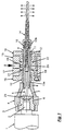
- FIG. 1 shows the mandrel 1 of a drill, which can be a portable, hand drill, or a drill mounted on a fixed or mobile support, guided on this support for example by a system of slides.
- the sleeve coupling 3, engaged on a protruding stud 2 of the mandrel, has an external thread on which a piece of clamp 4, intended to clamp and center a clamp a wick 5.
- a piece of clamp 4 intended to clamp and center a clamp a wick 5.
- the clamping piece 4 has an inner surface 6, bored to the diameter of an outer part of the workpiece coupling 3, a conical part 7 extending in front of the bore 6, and an end portion 8 cylindrical, threaded or reamed to receive the rear end of a shaft hollow 9 which constitutes the central part of the device described.
- This hollow shaft will preferably be made of hardened steel. he between the thread that connects it to the clamping piece 4 and another thread 10 located at its front end, a cylindrical seat 11 machined with precision so as to receive rolling bearings 12 schematically shown in Figure 1.
- the bore of the hollow shaft 9 has a rear part 13a adjusted to slip by relative to the diameter of the cylindrical part of the drill bit 5 and a front portion 13b of a slightly larger diameter. This part 13b extends to the end of the shaft 9, which present as already mentioned thread 10.
- the thread 10 is used for fixing a sealing cone 14, the internal diameter of which is equal to that of the bore 13a and therefore tightly surrounds the wick 5.
- the length of part 14 may vary as required. We can predict for each wick diameter a plurality of cones 14 of different lengths.
- the cone 14 can be made of steel, made of plastic or any other material. We will choose however preferably a material allowing the realization a reusable cone rather than disposable after a single use.
- the device for supplying the device described is completed by fitting 15 which consists of two discs bearing supports 16 and an intermediate sleeve 17 engaged on prominent parts of the supports 16.
- the discs 16 are screwed into the intermediate sleeve 17 at screw means 18.
- a radial duct 19 connects the sleeve 17 to a supply pipe (not shown). It leads in an annular chamber 20 which surrounds the shaft 9 to the location of its radial holes. Seals 21 and 22 are provided between parts 16 and 17 on the one hand, 16 and 9 on the other hand.
- the great advantage of the arrangement described is that it allows use a standard wick for injection, the diameter and length of the helical part can be choose at will.
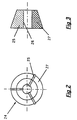
- This wick is engaged in the cone seal 14 and in the hollow shaft 9, its rear end being fixed to the mandrel 1 by the clamp shown in the figures 2 and 3 or by any other suitable clamping means.
- This clamp is a piece 24 of generally frustoconical shape whose external dimensions correspond to the dimensions internal of the frustoconical part 7 of the clamping part 4. It can have three metal parts 25 which form the clamping elements of the clamp. These parts are positioned so as to form a central passage 26 of a diameter adjusted to that of the drill bit 5. These metal parts are held by clamping in their position by the parts intermediates 27 made of elastic material, for example a relatively hard elastomer or one having springs.
- the piece 24 is compressed in the frustoconical space located in front the coupling 3, which ensures the training of the wick in rotation, as usual pliers made of three bit (chuck), the watertightness of the rear part being ensured by an O'ring seal 23 positioned in the groove of the part 3.
Landscapes
- Life Sciences & Earth Sciences (AREA)
- Engineering & Computer Science (AREA)
- Wood Science & Technology (AREA)
- Forests & Forestry (AREA)
- Auxiliary Devices For Machine Tools (AREA)
- Drilling Tools (AREA)
- Chemical And Physical Treatments For Wood And The Like (AREA)
- Earth Drilling (AREA)
Claims (7)
- Gerät zur Druckeinspritzung einer Flüssigkeit in ein Holzstück, mit einer Bohrmaschine mit einem Bohrer und mit einer Zulaufvorrichtung, die das Eindringen der Flüssigkeit in die Seitenwände eines durch diesen Bohrer gebohrten Loches ermöglicht, während dieser sich im Bohrloch befindet, dadurch gekennzeichnet, daß die Zulaufvorrichtung eine auf den Bohrer (5) justierte Hohlspindel (9) und einen ebenfalls auf den Bohrer justierten Dichtungskegel (14) aufweist, wobei die Hohlspindel mit einem ihrer Enden am Bohrfutter (1) der Bohrmaschine befestigt ist und mit einem mit einer Flüssigkeitversorgungsquelle verbundenen festen Anschlußteil (15) versehen ist, und der Dichtungskegel am anderen Ende der Hohlspindel befestigt und so ausgebildet ist, daß er mit seinem der Hohlspindel gegenüberliegenden Ende auf dem Holzstück an der Öffnung des Bohrloches zum Zeitpunkt des Einspritzens aufliegt und die Flüssigkeit durch die Kanäle in der Hohlspindel und das Gewinde des Bohrers fließt und die Seitenwände des Bohrloches erreicht.
- Gerät nach Anspruch 1, dadurch gekennzeichnet, daß die Hohlspindel durch eine Einspannvorrichtung (4) gehalten wird, die Teil des Bohrfutters der Bohrmaschine ist, und daß die Befestigung des Bohrers im Bohrfutter mit Hilfe einer Klemme (24), die ein auf den Bohrer angebrachtes und in die Einspannvorrichtung greifendes Teil aus elastischem Material aufweist, gewährleistet wird.
- Gerät nach Anspruch 2, dadurch gekennzeichnet, daß die Dichtigkeit des hinteren Teils durch eine O-Ring-Dichtung (23) gewährleistet wird.
- Gerät nach einem der vorhergehenden Ansprüche, dadurch gekennzeichnet, daß das Anschlußteil (15) auf der Hohlspindel (9) mittels Wälzlager (12) gelagert wird und eine Einführungsleitung (19) aufweist, die an einen Zulaufstutzen für die Flüssigkeitszufuhr angeschlossen ist, sowie eine Ringkammer (20), die den Teil der Hohlspindel umgibt, der mit Durchlaufkanälen versehen ist, wobei diese Kammer durch Dichtungsringe (21, 22) abgedichtet wird.
- Gerät nach einem der vorhergehenden Ansprüche, dadurch gekennzeichnet, daß die Hohlspindel und der Dichtungskegel aus gehärtetem Stahl bestehen.
- Gerät nach einem der Ansprüche 1 bis 4, dadurch gekennzeichnet, daß die Hohlspindel aus gehärtetem Stahl und der Dichtungskegel aus Kunststoff bestehen.
- Gerät nach einem der vorhergehenden Ansprüche, dadurch gekennzeichnet, daß es einen Satz Hohlspindeln umfaßt, die für Bohrer mit verschiedenen Durchmessern geeignet sind und an ein und derselben Einspannvorrichtung befestigt werden, wobei jede Hohlspindel mit einem eigenen Anschlußteil ausgestattet ist, sowie einen mehrteiligen Satz von Dichtungskegeln, die für die verschiedenen Durchmesser der Bohrer geeignet sind und die verschiedene Längen für jeden Durchmesser aufweisen.
Applications Claiming Priority (4)
| Application Number | Priority Date | Filing Date | Title |
|---|---|---|---|
| CH2609/95 | 1995-09-15 | ||
| CH02609/95A CH686768A5 (fr) | 1995-09-15 | 1995-09-15 | Appareil d'injection d'un liquide dans une pièce de bois. |
| CH260995 | 1995-09-15 | ||
| PCT/CH1996/000300 WO1997010084A1 (fr) | 1995-09-15 | 1996-09-03 | Appareil d'injection d'un liquide dans une piece de bois |
Publications (2)
| Publication Number | Publication Date |
|---|---|
| EP0863807A1 EP0863807A1 (de) | 1998-09-16 |
| EP0863807B1 true EP0863807B1 (de) | 1999-11-24 |
Family
ID=4237621
Family Applications (1)
| Application Number | Title | Priority Date | Filing Date |
|---|---|---|---|
| EP96927495A Expired - Lifetime EP0863807B1 (de) | 1995-09-15 | 1996-09-03 | Vorrichtung zur einspritzung von flüssigkeit in ein holzstück |
Country Status (5)
| Country | Link |
|---|---|
| EP (1) | EP0863807B1 (de) |
| AT (1) | ATE186866T1 (de) |
| CH (1) | CH686768A5 (de) |
| DE (1) | DE69605323T2 (de) |
| WO (1) | WO1997010084A1 (de) |
Families Citing this family (1)
| Publication number | Priority date | Publication date | Assignee | Title |
|---|---|---|---|---|
| WO1996038033A1 (en) * | 1995-05-30 | 1996-12-05 | Geoffrey Richard Eldridge | Tree injection apparatus |
Family Cites Families (3)
| Publication number | Priority date | Publication date | Assignee | Title |
|---|---|---|---|---|
| US1632508A (en) * | 1926-01-16 | 1927-06-14 | Schantz Carl | Method of preserving wood and the like |
| US4048353A (en) * | 1976-03-18 | 1977-09-13 | Canron, Inc. | Method of drilling and injecting perservative fluid into railway ties |
| IT8454160U1 (it) * | 1984-12-13 | 1986-06-13 | Edilchimica Italia S R L | Apparecchio per l'iniezione di liquidi disinfestanti e/o protettivi in strutture di legno ed altri materiali. |
-
1995
- 1995-09-15 CH CH02609/95A patent/CH686768A5/fr not_active IP Right Cessation
-
1996
- 1996-09-03 AT AT96927495T patent/ATE186866T1/de not_active IP Right Cessation
- 1996-09-03 EP EP96927495A patent/EP0863807B1/de not_active Expired - Lifetime
- 1996-09-03 DE DE69605323T patent/DE69605323T2/de not_active Expired - Fee Related
- 1996-09-03 WO PCT/CH1996/000300 patent/WO1997010084A1/fr not_active Ceased
Also Published As
| Publication number | Publication date |
|---|---|
| CH686768A5 (fr) | 1996-06-28 |
| DE69605323T2 (de) | 2000-07-27 |
| ATE186866T1 (de) | 1999-12-15 |
| DE69605323D1 (de) | 1999-12-30 |
| WO1997010084A1 (fr) | 1997-03-20 |
| EP0863807A1 (de) | 1998-09-16 |
Similar Documents
| Publication | Publication Date | Title |
|---|---|---|
| US6464266B1 (en) | Tube coupling | |
| EP2168703B1 (de) | Werkzeugträger mit Axialverstellung | |
| FR2585107A1 (fr) | Accouplement pour tuyau cannele | |
| EP1412107A1 (de) | Dehnungswerkzeug für aufweitzange | |
| FR2736988A1 (fr) | Raccord a tube | |
| FR2616862A1 (fr) | Dispositif d'accouplement debrayable a serrage hydraulique | |
| CH657685A5 (fr) | Raccord a action de serrage. | |
| FR2591309A1 (fr) | Raccord hydraulique a branchement manuel rapide pour canalisation de fluide | |
| FR2690966A3 (fr) | Outil destiné à désaérer des systèmes hydrauliques. | |
| EP0863807A1 (de) | Vorrichtung zur einspritzung von flüssigkeit in einem holzstückes | |
| FR2846070A1 (fr) | Dispositif de raccordement de deux tubes possedant une extremite evasee | |
| FR2632706A1 (fr) | Tubulure pour le montage preliminaire de la bague coupante ou de serrage d'un raccord visse de tuyauterie | |
| EP0187608B1 (de) | Schnellverbindung für unter Druck stehende Flüssigkeitssysteme in denen der Druck 150 bar erreichen kann | |
| EP0469999B1 (de) | Verfahren zur dichten Verbindung und entsprechende dichte Verbindung | |
| FR2638383A1 (fr) | Dispositif d'alimentation en liquide d'arrosage d'un mandrin flottant | |
| EP0541469B1 (de) | Kupplung für Kunststoffrohre und sein Montageverfahren | |
| FR2616698A1 (fr) | Sonde pour evaser simultanement, par voie hydraulique des parties longitudinales d'un arbre creux afin de fixer sur lui des pieces telles que des cames de pignons | |
| FR2518444A1 (fr) | Dispositif d'immobilisation ou d'entrainement par l'interieur de pieces cylindriques creuses | |
| FR2582771A2 (fr) | Raccord rapide pour circuits de fluide sous pression | |
| FR2558927A1 (fr) | Perfectionnement aux raccords rapides a verrouillage par billes | |
| FR2501088A1 (fr) | Dispositif a broche creuse et a mandrin combines | |
| FR2825774A1 (fr) | Raccords de passage de fluide | |
| FR2520087A1 (fr) | Dispositif pour faciliter le raccordement des tuyaux onduleux et procede pour le realiser | |
| EP0766034A1 (de) | Vorrichtung zum Verbinden von rohrförmigen Elementen mit Ventilgehäusen | |
| FR2697610A1 (fr) | Dispositif de guidage et raccord d'extrémité remplaçable pour extrémités de canalisations flexibles utilisables en mer. |
Legal Events
| Date | Code | Title | Description |
|---|---|---|---|
| PUAI | Public reference made under article 153(3) epc to a published international application that has entered the european phase |
Free format text: ORIGINAL CODE: 0009012 |
|
| 17P | Request for examination filed |
Effective date: 19980313 |
|
| AK | Designated contracting states |
Kind code of ref document: A1 Designated state(s): AT BE CH DE FR GB IT LI |
|
| GRAG | Despatch of communication of intention to grant |
Free format text: ORIGINAL CODE: EPIDOS AGRA |
|
| GRAG | Despatch of communication of intention to grant |
Free format text: ORIGINAL CODE: EPIDOS AGRA |
|
| GRAH | Despatch of communication of intention to grant a patent |
Free format text: ORIGINAL CODE: EPIDOS IGRA |
|
| 17Q | First examination report despatched |
Effective date: 19990128 |
|
| GRAH | Despatch of communication of intention to grant a patent |
Free format text: ORIGINAL CODE: EPIDOS IGRA |
|
| GRAA | (expected) grant |
Free format text: ORIGINAL CODE: 0009210 |
|
| AK | Designated contracting states |
Kind code of ref document: B1 Designated state(s): AT BE CH DE FR GB IT LI |
|
| REF | Corresponds to: |
Ref document number: 186866 Country of ref document: AT Date of ref document: 19991215 Kind code of ref document: T |
|
| REG | Reference to a national code |
Ref country code: CH Ref legal event code: NV Representative=s name: ABREMA AGENCE BREVETS ET MARQUES GANGUILLET & HUMP Ref country code: CH Ref legal event code: EP |
|
| GBT | Gb: translation of ep patent filed (gb section 77(6)(a)/1977) |
Effective date: 19991206 |
|
| REF | Corresponds to: |
Ref document number: 69605323 Country of ref document: DE Date of ref document: 19991230 |
|
| ITF | It: translation for a ep patent filed | ||
| PG25 | Lapsed in a contracting state [announced via postgrant information from national office to epo] |
Ref country code: GB Free format text: LAPSE BECAUSE OF NON-PAYMENT OF DUE FEES Effective date: 20000903 |
|
| PLBE | No opposition filed within time limit |
Free format text: ORIGINAL CODE: 0009261 |
|
| STAA | Information on the status of an ep patent application or granted ep patent |
Free format text: STATUS: NO OPPOSITION FILED WITHIN TIME LIMIT |
|
| 26N | No opposition filed | ||
| GBPC | Gb: european patent ceased through non-payment of renewal fee |
Effective date: 20000903 |
|
| PGFP | Annual fee paid to national office [announced via postgrant information from national office to epo] |
Ref country code: AT Payment date: 20010918 Year of fee payment: 6 |
|
| PGFP | Annual fee paid to national office [announced via postgrant information from national office to epo] |
Ref country code: BE Payment date: 20010919 Year of fee payment: 6 |
|
| PG25 | Lapsed in a contracting state [announced via postgrant information from national office to epo] |
Ref country code: AT Free format text: LAPSE BECAUSE OF NON-PAYMENT OF DUE FEES Effective date: 20020903 |
|
| PG25 | Lapsed in a contracting state [announced via postgrant information from national office to epo] |
Ref country code: BE Free format text: LAPSE BECAUSE OF NON-PAYMENT OF DUE FEES Effective date: 20020930 |
|
| BERE | Be: lapsed |
Owner name: *OVERNEY ANDRE Effective date: 20020930 |
|
| PG25 | Lapsed in a contracting state [announced via postgrant information from national office to epo] |
Ref country code: IT Free format text: LAPSE BECAUSE OF NON-PAYMENT OF DUE FEES;WARNING: LAPSES OF ITALIAN PATENTS WITH EFFECTIVE DATE BEFORE 2007 MAY HAVE OCCURRED AT ANY TIME BEFORE 2007. THE CORRECT EFFECTIVE DATE MAY BE DIFFERENT FROM THE ONE RECORDED. Effective date: 20050903 |
|
| PGFP | Annual fee paid to national office [announced via postgrant information from national office to epo] |
Ref country code: FR Payment date: 20060906 Year of fee payment: 11 |
|
| PGFP | Annual fee paid to national office [announced via postgrant information from national office to epo] |
Ref country code: CH Payment date: 20061120 Year of fee payment: 11 |
|
| PGFP | Annual fee paid to national office [announced via postgrant information from national office to epo] |
Ref country code: DE Payment date: 20061122 Year of fee payment: 11 |
|
| REG | Reference to a national code |
Ref country code: CH Ref legal event code: PL |
|
| PG25 | Lapsed in a contracting state [announced via postgrant information from national office to epo] |
Ref country code: LI Free format text: LAPSE BECAUSE OF NON-PAYMENT OF DUE FEES Effective date: 20070930 Ref country code: DE Free format text: LAPSE BECAUSE OF NON-PAYMENT OF DUE FEES Effective date: 20080401 Ref country code: CH Free format text: LAPSE BECAUSE OF NON-PAYMENT OF DUE FEES Effective date: 20070930 |
|
| REG | Reference to a national code |
Ref country code: FR Ref legal event code: ST Effective date: 20080531 |
|
| PG25 | Lapsed in a contracting state [announced via postgrant information from national office to epo] |
Ref country code: FR Free format text: LAPSE BECAUSE OF NON-PAYMENT OF DUE FEES Effective date: 20071001 |