EP0863818B1 - Dispositif de fixation amovible d'un siege au plancher d'un vehicule - Google Patents
Dispositif de fixation amovible d'un siege au plancher d'un vehicule Download PDFInfo
- Publication number
- EP0863818B1 EP0863818B1 EP96946171A EP96946171A EP0863818B1 EP 0863818 B1 EP0863818 B1 EP 0863818B1 EP 96946171 A EP96946171 A EP 96946171A EP 96946171 A EP96946171 A EP 96946171A EP 0863818 B1 EP0863818 B1 EP 0863818B1
- Authority
- EP
- European Patent Office
- Prior art keywords
- locking element
- locking
- spring
- fixing bolt
- primary
- Prior art date
- Legal status (The legal status is an assumption and is not a legal conclusion. Google has not performed a legal analysis and makes no representation as to the accuracy of the status listed.)
- Expired - Lifetime
Links
- 230000008878 coupling Effects 0.000 claims description 12
- 238000010168 coupling process Methods 0.000 claims description 12
- 238000005859 coupling reaction Methods 0.000 claims description 12
- 210000000078 claw Anatomy 0.000 claims description 8
- 239000000725 suspension Substances 0.000 claims description 3
- 230000000903 blocking effect Effects 0.000 claims 4
- 238000000034 method Methods 0.000 description 14
- 208000027418 Wounds and injury Diseases 0.000 description 3
- 230000006378 damage Effects 0.000 description 3
- 208000014674 injury Diseases 0.000 description 3
- 230000001133 acceleration Effects 0.000 description 1
- 230000006835 compression Effects 0.000 description 1
- 238000007906 compression Methods 0.000 description 1
- 238000006073 displacement reaction Methods 0.000 description 1
- 230000002349 favourable effect Effects 0.000 description 1
- 238000003780 insertion Methods 0.000 description 1
- 230000037431 insertion Effects 0.000 description 1
- 238000004519 manufacturing process Methods 0.000 description 1
- 230000013011 mating Effects 0.000 description 1
- 230000007246 mechanism Effects 0.000 description 1
Images



Classifications
-
- B—PERFORMING OPERATIONS; TRANSPORTING
- B60—VEHICLES IN GENERAL
- B60N—SEATS SPECIALLY ADAPTED FOR VEHICLES; VEHICLE PASSENGER ACCOMMODATION NOT OTHERWISE PROVIDED FOR
- B60N2/00—Seats specially adapted for vehicles; Arrangement or mounting of seats in vehicles
- B60N2/005—Arrangement or mounting of seats in vehicles, e.g. dismountable auxiliary seats
- B60N2/015—Attaching seats directly to vehicle chassis
- B60N2/01508—Attaching seats directly to vehicle chassis using quick release attachments
- B60N2/01516—Attaching seats directly to vehicle chassis using quick release attachments with locking mechanisms
- B60N2/01583—Attaching seats directly to vehicle chassis using quick release attachments with locking mechanisms locking on transversal elements on the vehicle floor or rail, e.g. transversal rods
Definitions
- the invention relates to a device for releasable connection a vehicle seat according to the preamble of the claim 1 (see for example US-A-5 282 662). It ensures secure locking and if necessary, a simple unlocking of the vehicle seat.
- DE-A1 44 04 935 describes a device for connecting a vehicle seat with a vehicle floor known to lock the seat with a bolt of the front Bearing blocks a two-armed locking lever and Lock with the bolt of the rear bracket hooks open in the direction of travel.
- the two-armed Locking lever is in the unlocked position a spring held in a stop, the free end one arm a stop attached to the vehicle floor assigned.
- the Seat After inserting the attachment point of the vehicle seat in the bottom bracket is the Seat for the production of the positive locking after pushed forward, with the rear mounting bolt penetrates between the flanks of the rear fastening hook.
- the front seat slides on a guide link a support plate that also the two-armed Locking lever carries, diagonally downwards. It happens to engage the base support with one arm of the locking lever and for pivoting it in the direction the locking position.
- the direction of action of the spring is reversed the locking element around, which this automatically in the locking position is pulled.
- the described device enables a simple one Locking and unlocking a vehicle seat, it owns however, the disadvantage that the rear locking point in The shape of an open hook is designed to counteract forces in the direction of travel. in case of a Heckcrashs had the entire front locking point derive associated energy. Furthermore, can not be completely excluded that the seat in front bearing block is locked while the rear Fastening hook does not enclose the fastening bolt, but gets up on it. Such an unsecured seat poses a significant risk of accident and injury.
- DE 44 08 686 C1 describes a device for connecting a side member of a vehicle seat with the vehicle structure, with a fastening claw open to the rear grips around a body-fixed fastening bolt, so that crash forces caused by the rear are absorbed can be. After the rear attachment area in the front Fastening claw on the assigned fastening bolts lowered and secured by means of a locking element become.
- a device for detachable Connection of a vehicle seat to the vehicle floor which has two front and rear guide links, engage in the respective fastening bolts.
- the vehicle seat is fastened to the fastening bolts by means of fastening hooks attached or locked with these.
- the device has a rod which has a support foot connects to one leg of the vehicle seat. To take out the vehicle seat is in a vertical position folded, with the rear guide links (or Legs of the seat) because of the connection with the support foot fold over the bar.
- EP 0 609 130 A1 describes a device for releasable Connection of a vehicle seat to the vehicle floor described, which has a rear fastening hook, which engages in a vehicle-side fastening bolt.
- a front guide link serves as support the vehicle seat on a front mounting bolt.
- the rear mounting bolt is a pivoted, assigned claw-like primary locking element, that of a spring force against the locking position is acted upon.
- This primary locking element is by a secondary locking element in the form of a foot lever unlockable and lockable.
- Another device for releasably attaching a Vehicle seat is known from EP 0 618 102 A1.
- the invention is therefore based on the object of a device for releasably locking a vehicle seat with to provide the floor of a motor vehicle, which is a simple and safe locking and unlocking guaranteed of the vehicle seat.
- a coupling element for example a coupling rod, connected to each other, being the one for the pivotal movements of the front Locking element and the secondary locking element required force from a common spring element is applied. This can ensure that locking the seat with the front mounting bolt can only be done when the rear seat lock completed properly.
- the last described embodiment around a locking element added that the triggering of the locking process on the front fastening bolt does not allow if the Fastening bolts have not yet reached the intended area Has reached the front gusset. That too pivotable locking element loaded by a spring prevented by supporting the locking element its locking movement until the locking element from the fastening bolt against the spring force from the overlap area the backdrop is ousted.
- the claw-like, pivoted primary locking element from a spring element against the locking direction acted upon and initially by a secondary element held a position that is the entrance to the backdrop of the Fastening hook overlaps. This is how it arrives during assembly of the seat to the vehicle floor of the fastening hooks first in the claw of the primary locking element and only subsequently in the backdrop of the fastening hook. Locked when the intended locking position is reached the secondary locking element the position of the primary locking element and thus also the location of the Fastening bolt in the backdrop of the fastening hook.
- the secondary locking element is also preferred spring loaded so that the locking process is practically automatic and runs safely.
- This handle is also easy to loosen the front and rear locking possible. After the The handle is pulled up, the locking element falls again in front of the locking element in the scenery area the gusset.
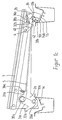
- FIG. 1a shows schematically the structure a seat base, the locking elements of which Vehicle seat over those belonging to the bearing blocks 1a, 1b Connect the fastening bolts 10a, 10b to the vehicle floor.
- the schematic representation of the seat frame is essentially limited to the guide rail 7, the form-fitting and movable with one on one (not shown) seat frame mounted guide rail is engaged, and the support plate 2a, the on the one hand with its backdrop 20a part of the front locking and on the other hand the locking element 3a in the pivot axis 30a carries.
- the rear seat attachment has an attachment hook 2b with a link 20b open to the front for the fastening bolt 10b on. But first is the entrance to the backdrop 20b of the claws 33b, 34b of the primary locking element 3b blocked by a tension spring 36b its stop 37b against the secondary locking element is pressed. For this purpose, the tension spring 36b engages one the arm 35b opposite the claw region indicates that the Claw 33b, 34b in the direction of the opening of the link 20b is pulled.
- the front fastening bolt is in this starting position 10a at stop 21a, which is directly in the backdrop 20a opens.
- a locking pivotal movement of the locking element 3a must not yet take place, since the hook 33a still the bolt 10a in this position cannot capture.
- One who exercises on arm 31a exercises and in the support plate 2a suspended tension spring 36a a corresponding directed force on the locking element 3a, however, the pivoting movement is achieved by a coupling rod 5 locked on the one hand via their front attachment 310 with the arm 31a and on the other hand via its rear attachment articulated to the secondary locking element is.
- Through the coupling rod 5 not only kinematic processes of the front and rear locking elements coordinated, but it will also be for those Functionality of the device according to the invention necessary spring force of the tension spring 36a to the secondary locking element 4 forwarded.
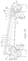
- FIG. 1b shows a further phase of the assembly or locking process, in which the seat frame by a certain Route was moved forward. Clearly visible is that the fastening bolt 10b against the stop 34b presses. The associated pivoting movement of the Primary locking element 3b about the axis 30b leads to an increase in the tension between the seat frame and Arm 35b suspended spring 36b.
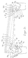
- Figure 1c shows the device fully locked State in which both fastening bolts 10a, 10b are provided Positions taken in the scenes 20a, 20b and the locking elements 3a, 3b these positions have locked.
- the bolt 10a is locked Pivotal movement of the locking element 3a.
- the handle 32a in a position to control the proper locking can be used.
- the handle 32a will lock front directly and rear indirectly by swiveling the Secondary locking element 4 via the coupling rod solved.
- the seat With the support of the spring 36b, the seat can now are pushed backwards, the claw 33b, 34b of the forward-pivoting primary locking element 3b the Mounting bolts gradually releases. So get the Seat and its locking elements in a position like it is shown in Figure 1a.
- the seat can now be easily be lifted out of the pedestals 1a, 1b.
- Figures 2a to 2c show a further development of the previously described embodiment variant in analog sequences the assembly process by adding a Locking element 6 has an increased security standard. It also ensures the locking of the front mounting bolt 10a can only be done if the bolt 10a assumed the prescribed locking position Has. Release of the spring biased by the spring 36b Primary locking element 3b by the secondary locking element 4 cannot swing in on its own of the front locking element 3'a in the area the backdrop 20a lead.
- the locking element 6 is supported by the locking element 3'a opposite end pivotable on the support plate 2a and covered before the locking process begins (see Figure 2a) most of the backdrop 20a, with the free End with the curve portion 62 and the nose 61 in engagement with the projecting stop 34a of the locking element 3'a stands and supports this against pivoting.
- a spring 63 presses the stops 34a and 61 against each other.
- the locking mechanisms are preferably one on the other matched that the curve portion 31b with respect of the stop 41 in the rear locking area and the Curve section 62 and the stop 34a in the front locking area at about the same time during the assembly process disengage.
- the spring 36a drives the Locking process on, the stop 34a the locking element 6 continues to press against the spring 63 and the hook-shaped Stop 33a engages under the fastening bolt 10a.
Landscapes
- Engineering & Computer Science (AREA)
- Aviation & Aerospace Engineering (AREA)
- Transportation (AREA)
- Mechanical Engineering (AREA)
- Seats For Vehicles (AREA)
Claims (11)
- Dispositif de liaison amovible d'un siège de véhicule au plancher dudit véhicule, comprenant un crochet postérieur de fixation (2b) de type ouvert, dans lequel peut pénétrer un boulon de fixation (10b) situé côté plancher du véhicule, et une coulisse antérieure de guidage (20a) en vue de l'appui du siège du véhicule sur un boulon antérieur de fixation (10a), ainsi qu'un élément antérieur de verrouillage (3a, 3'a) du type griffe, monté à rotation, sollicité par une force élastique et arrêtant le boulon antérieur de fixation (10a) dans la coulisse de guidage (20a) dispositif dans lequel est affecté, au boulon postérieur de fixation (10b), un élément de verrouillage primaire (3b) du type griffe, monté à pivotement, sollicité par une force élastique en sens inverse de la position de verrouillage, et dont la position est pareillement verrouillable par un élément de verrouillage secondaire (4) lorsque la position de verrouillage est atteinte,
caractérisé par le fait
que l'élément antérieur de verrouillage (3a, 3a') et l'élément postérieur de verrouillage secondaire (4) sont reliés l'un à l'autre par un élément d'accouplement (5) de telle sorte que la force élastique agissant sur l'élément antérieur de verrouillage (3a, 3a') puisse être transmise à l'élément de verrouillage secondaire (4), et que l'élément antérieur de verrouillage (3a, 3a') ne puisse ètre actionné que lorsque l'élément de verrouillage primaire (3b) a atteint sa position de verrouillage. - Dispositif selon la revendication 1, caractérisé par le fait que l'élément de verrouillage primaire (3b) présente deux butées (33b, 34b) formant une griffe pour recevoir le boulon postérieur de fixation (10b).
- Dispositif selon au moins l'une des revendications précédentes, caractérisé par le fait que l'élément de verrouillage secondaire (4) est sollicité, par une force élastique, en direction de sa position de verrouillage.
- Dispositif selon au moins l'une des revendications précédentes, caractérisé par le fait qu'un premier segment de came (31b) est façonné d'un seul tenant sur l'élément de verrouillage primaire (3b), segment contre lequel une première butée (41) de l'élément de verrouillage secondaire (4) s'applique aussi longtemps que le boulon de fixation (10b) n'a pas encore atteint sa position de verrouillage à l'intérieur de la coulisse (20b) du crochet de fixation (2b) ; et par le fait que, lorsque la position de verrouillage est atteinte, l'élément de verrouillage secondaire (4) sollicité par une force élastique pivote, par un segment de came (42), en opposition vis-à-vis d'un second segment de came (32b) de l'élément de verrouillage primaire (3b), et verrouille ainsi la position du boulon de fixation (10b) dans la direction de déplacement.
- Dispositif selon au moins l'une des revendications précédentes, caractérisé par le fait qu'on utilise, en tant qu'élément d'accouplement, une tige (5) dont l'une des extrémités est en liaison avec l'élément de verrouillage secondaire (4) par l'intermédiaire d'un système d'accrochage (43), et dont l'autre extrémité est en liaison avec l'élément antérieur de verrouillage (3a) par l'intermédiaire d'un système d'accrochage (310), au moyen d'un bras (31a) qui y est ménagé d'un seul tenant.
- Dispositif selon au moins l'une des revendications précédentes, caractérisé par le fait qu'il est prévu un ressort (36a) provoquant le mouvement pivotant tant de l'élément antérieur de verrouillage (3a), que de l'élément de verrouillage secondaire (4).
- Dispositif selon la revendication 6, caractérisé par le fait que le ressort (36a) vient en prise avec le bras (31a) de l'élément antérieur de verrouillage (3a).
- Dispositif selon la revendication 6, caractérisé par le fait que le ressort vient en prise avec la tige d'accouplement (5) à proximité du verrouillage postérieur, et sollicite ladite tige en direction dudit verrouillage postérieur.
- Dispositif selon au moins l'une des revendications précédentes, caractérisé par le fait que l'élément antérieur de verrouillage (3'a) est affecté à un élément de blocage (6) empêchant un pivotement de l'élément de verrouillage (3'a), vers la position de verrouillage, aussi longtemps que le boulon antérieur de fixation (10a) pénètre dans la coulisse antérieure de guidage (20a).
- Dispositif selon la revendication 9, caractérisé par le fait que, en position de blocage, l'élément de blocage (6) recouvre au moins partiellement la zone de verrouillage de la coulisse antérieure de guidage (20a), et est monté à pivotement dans un axe (60), l'extrémité libre, située en vis-à-vis de l'axe, comprenant un segment de came (62) dirigé axialement à l'opposé d'une butée (34a) de l'élément de verrouillage (3'a), et un mentonnet (61) qui limite la plage de pivotement de l'élément de blocage (6) par venue en prise avec la butée (34a).
- Dispositif selon les revendications 9 et 10, caractérisé par le fait que l'élément de blocage (6) est sollicité, par un ressort (63), en sens inverse du dispositif de verrouillage (dans la direction de la coulisse antérieure 20a).
Applications Claiming Priority (3)
| Application Number | Priority Date | Filing Date | Title |
|---|---|---|---|
| DE19544833 | 1995-12-01 | ||
| DE19544833A DE19544833C2 (de) | 1995-12-01 | 1995-12-01 | Vorrichtung zur lösbaren Verbindung eines Fahrzeugsitzes mit dem Fahrzeugboden |
| PCT/DE1996/002327 WO1997019829A2 (fr) | 1995-12-01 | 1996-11-28 | Dispositif de fixation amovible d'un siege au plancher d'un vehicule |
Publications (2)
| Publication Number | Publication Date |
|---|---|
| EP0863818A2 EP0863818A2 (fr) | 1998-09-16 |
| EP0863818B1 true EP0863818B1 (fr) | 1999-09-22 |
Family
ID=7778925
Family Applications (1)
| Application Number | Title | Priority Date | Filing Date |
|---|---|---|---|
| EP96946171A Expired - Lifetime EP0863818B1 (fr) | 1995-12-01 | 1996-11-28 | Dispositif de fixation amovible d'un siege au plancher d'un vehicule |
Country Status (6)
| Country | Link |
|---|---|
| US (1) | US6244649B1 (fr) |
| EP (1) | EP0863818B1 (fr) |
| DE (2) | DE19544833C2 (fr) |
| ES (1) | ES2138403T3 (fr) |
| MX (1) | MX9804341A (fr) |
| WO (1) | WO1997019829A2 (fr) |
Families Citing this family (18)
| Publication number | Priority date | Publication date | Assignee | Title |
|---|---|---|---|---|
| DE19846031C2 (de) * | 1997-10-08 | 2002-01-17 | Mitsubishi Motors Corp | Lösbarer Klappsitz |
| DE19822262A1 (de) * | 1998-05-18 | 1999-11-25 | Lear Corp | Vorrichtung zur Montage eines Sitzes an einem Fahrzeug |
| CA2339642C (fr) | 1998-10-09 | 2008-05-27 | Magna Seating Systems Inc. | Ensemble siege rabattable et basculant automatique pour vehicule |
| DE19852540A1 (de) | 1998-11-05 | 2000-05-11 | Brose Fahrzeugteile | Vorrichtung zur lösbaren Befestigung eines Fahrzeugsitzes oder von Teilen eines Fahrzeugsitzes in einem Kraftfahrzeug |
| DE19908030B4 (de) * | 1999-02-24 | 2004-09-09 | Lander Automotive Gmbh | Verriegelungsvorrichtung für einen Fahrzeugsitz an einem Fahrzeugchassis |
| DE19916422B4 (de) * | 1999-04-07 | 2006-07-27 | Brose Fahrzeugteile Gmbh & Co. Kommanditgesellschaft, Coburg | Vorrichtung zur lösbaren Befestigung eines Fahrzeugsitzes am Fahrzeugboden |
| DE10042115A1 (de) * | 2000-08-28 | 2002-03-14 | Burger Soehne | Verriegelungsvorrichtung für einen Fahrzeugsitz an einem Fahrzeugchassis |
| FR2816556B1 (fr) * | 2000-11-10 | 2003-02-07 | Peugeot Citroen Automobiles Sa | Mecanisme d'articulation pour siege ou banquette arriere reglable longitudinalement, notamment pour vehicule automobile |
| US7013497B1 (en) | 2002-03-15 | 2006-03-21 | Athletic Specialties, Inc. | Strap-securing device |
| US20040021354A1 (en) * | 2002-07-31 | 2004-02-05 | Hogg Mark G. | Tiltable spring-biased chair |
| US6692051B1 (en) | 2002-08-07 | 2004-02-17 | Paccar Inc | Tractor-truck cab with workstation and mobile seat |
| DE20304508U1 (de) * | 2003-03-14 | 2004-07-29 | Brose Fahrzeugteile Gmbh & Co. Kg, Coburg | Vorrichtung zum Verbinden eines Fahrzeugsitzes mit einem Fahrzeugboden |
| US7073862B2 (en) * | 2003-07-31 | 2006-07-11 | Intier Automotive Inc. | Tumble seat assembly having locking strut |
| US20070057555A1 (en) * | 2005-09-12 | 2007-03-15 | Lear Corporation | Latch assembly for a vehicle seat |
| EP2504234B1 (fr) * | 2009-11-23 | 2017-12-20 | Zodiac Seats US LLC | Ensemble de cuvette de siège |
| JP2014195588A (ja) * | 2013-03-29 | 2014-10-16 | キヤノン株式会社 | 放射線発生用装置及び放射線撮影装置 |
| ES2684481T3 (es) * | 2016-03-07 | 2018-10-03 | Innovation and Safety S.L | Asiento desmontable |
| US10618430B2 (en) * | 2018-05-09 | 2020-04-14 | Polaris Industries Inc. | Seat latch mechanism |
Family Cites Families (9)
| Publication number | Priority date | Publication date | Assignee | Title |
|---|---|---|---|---|
| US4495887A (en) | 1978-12-20 | 1985-01-29 | Mondrush Ronald L | Seat |
| FR2682333B1 (fr) * | 1991-10-10 | 1994-01-07 | Peugeot Automobiles | Dispositif de verrouillage d'un siege sur un plancher, en particulier pour vehicule automobile, et siege equipe de ce dispositif. |
| US5238285A (en) * | 1992-07-16 | 1993-08-24 | Douglas & Lomason Company | Folding vehicle bedseat |
| US5282662A (en) * | 1992-12-14 | 1994-02-01 | General Motors Corporation | Rear seat for all purpose vehicle |
| FR2700735B1 (fr) * | 1993-01-27 | 1995-04-07 | Matra Automobile | Siège de véhicule enlevable et réglable en position. |
| US5372398A (en) | 1993-04-02 | 1994-12-13 | Chrysler Corporation | Vehicle seat assembly with retracting latch/engaging roller seat-to-floor lock |
| DE4404935B4 (de) * | 1994-02-11 | 2004-05-27 | Brose Fahrzeugteile Gmbh & Co. Kommanditgesellschaft, Coburg | Vorrichtung zum Verbinden eines Fahrzeugsitzes mit einem Fahrzeugboden |
| DE4408686C1 (de) * | 1994-03-15 | 1995-04-27 | Keiper Recaro Gmbh Co | Vorrichtung zum Verbinden eines Längsträgers eines Fahrzeugsitzes mit der Fahrzeugstruktur |
| JP3500717B2 (ja) * | 1994-08-31 | 2004-02-23 | アイシン精機株式会社 | 車両用シート装置 |
-
1995
- 1995-12-01 DE DE19544833A patent/DE19544833C2/de not_active Expired - Fee Related
-
1996
- 1996-11-28 WO PCT/DE1996/002327 patent/WO1997019829A2/fr not_active Ceased
- 1996-11-28 EP EP96946171A patent/EP0863818B1/fr not_active Expired - Lifetime
- 1996-11-28 ES ES96946171T patent/ES2138403T3/es not_active Expired - Lifetime
- 1996-11-28 US US09/077,587 patent/US6244649B1/en not_active Expired - Lifetime
- 1996-11-28 DE DE59603189T patent/DE59603189D1/de not_active Expired - Lifetime
-
1998
- 1998-06-01 MX MX9804341A patent/MX9804341A/es unknown
Also Published As
| Publication number | Publication date |
|---|---|
| EP0863818A2 (fr) | 1998-09-16 |
| MX9804341A (es) | 1998-09-30 |
| US6244649B1 (en) | 2001-06-12 |
| ES2138403T3 (es) | 2000-01-01 |
| DE59603189D1 (de) | 1999-10-28 |
| WO1997019829A3 (fr) | 1997-09-12 |
| WO1997019829A2 (fr) | 1997-06-05 |
| DE19544833C2 (de) | 2001-06-21 |
| DE19544833A1 (de) | 1997-06-05 |
Similar Documents
| Publication | Publication Date | Title |
|---|---|---|
| EP0863818B1 (fr) | Dispositif de fixation amovible d'un siege au plancher d'un vehicule | |
| EP1517810B1 (fr) | Bâti de fixation et dispositif de retenue avec bâti de fixation | |
| DE19932214B4 (de) | Fahrzeugsitz | |
| DE19715764C2 (de) | Neigungseinstellbeschlag mit Freischwenkeinrichtung für eine Rückenlehne eines Kraftfahrzeugsitzes | |
| DE3726711C2 (fr) | ||
| EP1034974B1 (fr) | Siège de véhicule | |
| DE69607246T2 (de) | Sicherungsbefestigung für herausnehmbare Fahrzeugsitze | |
| DE4012860C2 (de) | Freischwenkeinrichtung für die Rückenlehne eines Fahrzeugsitzes, insbesondere Kraftfahrzeugsitzes | |
| DE69604373T2 (de) | Sitz mit veränderlicher Anordnung für Kraftfahrzeuge | |
| DE3923989A1 (de) | Fahrzeugsitzgelenk | |
| EP2920025A1 (fr) | Siège de véhicule, en particulier siège de véhicule automobile | |
| DE3517877A1 (de) | Einstellbare sitzanordnung | |
| DE10139538C1 (de) | Fondsitz für Kraftfahrzeuge | |
| EP0970844A1 (fr) | Siège modulaire | |
| WO1997019829A9 (fr) | Dispositif de fixation amovible d'un siege au plancher d'un vehicule | |
| DE69700556T2 (de) | Nach vorn bewegbarer Fahrzeugsitz, um zu einem hinteren Raum zu gelangen | |
| EP0763444B1 (fr) | Siège arrière pour véhicules automobiles, en particulier pour voitures | |
| DE69406157T2 (de) | Fahrzeugsitz und dessen Anwendung bei einem Rücksitz | |
| DE602004009566T2 (de) | Autokindersitz, schwenkbar zwischen einer nach vorne und einer türwärts gerichteten Position , mit einer automatischen Rückstellung nach vorne | |
| EP1126990B1 (fr) | Dispositif pour la fixation amovible d'un siège de véhicule ou de parties d'un siège de véhicule dans un véhicule automobile | |
| DE3826932C2 (fr) | ||
| EP1765632B1 (fr) | Systeme de securite pour siege de vehicule | |
| EP1581408B1 (fr) | Siege de vehicule automobile et banquette de siege de vehicule automobile | |
| EP1332066B1 (fr) | Système de leviers articulés pour chassis de siège | |
| DE29522335U1 (de) | Vorrichtung zur lösbaren Verbindung eines Fahrzeugsitzes mit dem Fahrzeugboden |
Legal Events
| Date | Code | Title | Description |
|---|---|---|---|
| PUAI | Public reference made under article 153(3) epc to a published international application that has entered the european phase |
Free format text: ORIGINAL CODE: 0009012 |
|
| 17P | Request for examination filed |
Effective date: 19980626 |
|
| AK | Designated contracting states |
Kind code of ref document: A2 Designated state(s): DE ES FR GB IT SE |
|
| 17Q | First examination report despatched |
Effective date: 19980917 |
|
| GRAG | Despatch of communication of intention to grant |
Free format text: ORIGINAL CODE: EPIDOS AGRA |
|
| GRAG | Despatch of communication of intention to grant |
Free format text: ORIGINAL CODE: EPIDOS AGRA |
|
| GRAH | Despatch of communication of intention to grant a patent |
Free format text: ORIGINAL CODE: EPIDOS IGRA |
|
| GRAH | Despatch of communication of intention to grant a patent |
Free format text: ORIGINAL CODE: EPIDOS IGRA |
|
| GRAA | (expected) grant |
Free format text: ORIGINAL CODE: 0009210 |
|
| AK | Designated contracting states |
Kind code of ref document: B1 Designated state(s): DE ES FR GB IT SE |
|
| REF | Corresponds to: |
Ref document number: 59603189 Country of ref document: DE Date of ref document: 19991028 |
|
| ITF | It: translation for a ep patent filed | ||
| ET | Fr: translation filed | ||
| GBT | Gb: translation of ep patent filed (gb section 77(6)(a)/1977) |
Effective date: 19991201 |
|
| REG | Reference to a national code |
Ref country code: ES Ref legal event code: FG2A Ref document number: 2138403 Country of ref document: ES Kind code of ref document: T3 |
|
| PLBE | No opposition filed within time limit |
Free format text: ORIGINAL CODE: 0009261 |
|
| STAA | Information on the status of an ep patent application or granted ep patent |
Free format text: STATUS: NO OPPOSITION FILED WITHIN TIME LIMIT |
|
| 26N | No opposition filed | ||
| REG | Reference to a national code |
Ref country code: GB Ref legal event code: IF02 |
|
| PGFP | Annual fee paid to national office [announced via postgrant information from national office to epo] |
Ref country code: SE Payment date: 20051107 Year of fee payment: 10 |
|
| PGFP | Annual fee paid to national office [announced via postgrant information from national office to epo] |
Ref country code: GB Payment date: 20051123 Year of fee payment: 10 |
|
| PG25 | Lapsed in a contracting state [announced via postgrant information from national office to epo] |
Ref country code: SE Free format text: LAPSE BECAUSE OF NON-PAYMENT OF DUE FEES Effective date: 20061129 |
|
| PGFP | Annual fee paid to national office [announced via postgrant information from national office to epo] |
Ref country code: IT Payment date: 20061130 Year of fee payment: 11 |
|
| EUG | Se: european patent has lapsed | ||
| GBPC | Gb: european patent ceased through non-payment of renewal fee |
Effective date: 20061128 |
|
| PG25 | Lapsed in a contracting state [announced via postgrant information from national office to epo] |
Ref country code: GB Free format text: LAPSE BECAUSE OF NON-PAYMENT OF DUE FEES Effective date: 20061128 |
|
| PGFP | Annual fee paid to national office [announced via postgrant information from national office to epo] |
Ref country code: ES Payment date: 20071219 Year of fee payment: 12 |
|
| PGFP | Annual fee paid to national office [announced via postgrant information from national office to epo] |
Ref country code: FR Payment date: 20071108 Year of fee payment: 12 |
|
| PG25 | Lapsed in a contracting state [announced via postgrant information from national office to epo] |
Ref country code: IT Free format text: LAPSE BECAUSE OF NON-PAYMENT OF DUE FEES Effective date: 20071128 |
|
| REG | Reference to a national code |
Ref country code: FR Ref legal event code: ST Effective date: 20090731 |
|
| REG | Reference to a national code |
Ref country code: ES Ref legal event code: FD2A Effective date: 20081129 |
|
| PG25 | Lapsed in a contracting state [announced via postgrant information from national office to epo] |
Ref country code: ES Free format text: LAPSE BECAUSE OF NON-PAYMENT OF DUE FEES Effective date: 20081129 |
|
| PG25 | Lapsed in a contracting state [announced via postgrant information from national office to epo] |
Ref country code: FR Free format text: LAPSE BECAUSE OF NON-PAYMENT OF DUE FEES Effective date: 20081130 |
|
| PGFP | Annual fee paid to national office [announced via postgrant information from national office to epo] |
Ref country code: DE Payment date: 20121130 Year of fee payment: 17 |
|
| REG | Reference to a national code |
Ref country code: DE Ref legal event code: R119 Ref document number: 59603189 Country of ref document: DE Effective date: 20140603 |
|
| PG25 | Lapsed in a contracting state [announced via postgrant information from national office to epo] |
Ref country code: DE Free format text: LAPSE BECAUSE OF NON-PAYMENT OF DUE FEES Effective date: 20140603 |