EP0864281A2 - Dispositif de dévidage - Google Patents
Dispositif de dévidage Download PDFInfo
- Publication number
- EP0864281A2 EP0864281A2 EP98101873A EP98101873A EP0864281A2 EP 0864281 A2 EP0864281 A2 EP 0864281A2 EP 98101873 A EP98101873 A EP 98101873A EP 98101873 A EP98101873 A EP 98101873A EP 0864281 A2 EP0864281 A2 EP 0864281A2
- Authority
- EP
- European Patent Office
- Prior art keywords
- guide element
- roll
- circulation guide
- unwinding device
- unwinding
- Prior art date
- Legal status (The legal status is an assumption and is not a legal conclusion. Google has not performed a legal analysis and makes no representation as to the accuracy of the status listed.)
- Withdrawn
Links
- 239000000463 material Substances 0.000 claims abstract description 90
- 238000004806 packaging method and process Methods 0.000 claims abstract description 7
- 239000000696 magnetic material Substances 0.000 description 3
- 239000011888 foil Substances 0.000 description 2
- 238000004804 winding Methods 0.000 description 2
- 230000006978 adaptation Effects 0.000 description 1
- 238000005452 bending Methods 0.000 description 1
- 230000015572 biosynthetic process Effects 0.000 description 1
- 239000003086 colorant Substances 0.000 description 1
- 238000010276 construction Methods 0.000 description 1
- 230000000694 effects Effects 0.000 description 1
- 230000002349 favourable effect Effects 0.000 description 1
- 238000004519 manufacturing process Methods 0.000 description 1
- 239000002184 metal Substances 0.000 description 1
- 239000005022 packaging material Substances 0.000 description 1
- 230000003134 recirculating effect Effects 0.000 description 1
- 230000003716 rejuvenation Effects 0.000 description 1
- 239000011343 solid material Substances 0.000 description 1
- 239000008207 working material Substances 0.000 description 1
Images

Classifications
-
- B—PERFORMING OPERATIONS; TRANSPORTING
- B65—CONVEYING; PACKING; STORING; HANDLING THIN OR FILAMENTARY MATERIAL
- B65H—HANDLING THIN OR FILAMENTARY MATERIAL, e.g. SHEETS, WEBS, CABLES
- B65H49/00—Unwinding or paying-out filamentary material; Supporting, storing or transporting packages from which filamentary material is to be withdrawn or paid-out
- B65H49/02—Methods or apparatus in which packages do not rotate
- B65H49/04—Package-supporting devices
- B65H49/14—Package-supporting devices for several operative packages
- B65H49/16—Stands or frameworks
Definitions
- the invention relates to an unwinder for Unwinding of windable material, in particular Wire, from at least one roll of material Preamble of claim 1.
- Unwinding devices of the type mentioned here include a shelf for at least a roll of material, also called a spool, for example a wire reel.
- the roll of material is on the shelf by means of a circulation guide element which fixes the free diameter reaches through the roll of material.
- the circulation guide element is by means of a screw or locking connection firmly connected to the shelf.
- the material roll be packed, for example in a box or shrink-wrapped in foil, and different have large free diameter and dimensions.
- the material roll is unwound from the inside, the unwound material on the outside of the circulation guide element rests and is managed. Thereby can prevent the material from knotting will.
- an unwinder proposed that mentioned in claim 1
- the rolls of material can, for example, different sized free Have diameter and / or dimensions. It is but also possible that the material rolls are different are packed, for example in foil or box, or have no packaging at all.
- the magnetic holder can be easily and without elaborate processing of the shelf and the circulation guide element are made so that the Effort to manufacture the unwinder reduced and thus their costs are reduced can.
- the core has a length that is greater than the width or the thickness the roll of material so that the free diameter of the Roll of material is penetrated by the core.
- the end of the core facing away from the shelf thus protrudes the material roll lying on the shelf, whereby an uncontrolled unwinding and possibly knotting can be reliably prevented.
- the core consists partly or completely of one magnetic material and forms together with made of a magnetizable material Put down the magnetic holder.
- the tray made of a magnetic material and the core made of a magnetizable material getting produced.
- the filing and the core is made of a magnetic material.
- the core can also be designed as a hollow body be in the magnetic or magnetizable material is used. But it is also possible that the core is made of solid material.
- the circulation guide element can a circular cylindrical, conical or frustoconical Have shape, with a tapered or frustoconical circulation guide element thereof the larger diameter end of the Storage is assigned.
- the circulation guide element has a curved outer contour, for example, trumpet-shaped, the the larger diameter end of the circulation guide element is assigned to the shelf.
- An embodiment of the unwinding device is also preferred, in the between circulation guide element and storage using the magnetic holder Pinching area of packaging of material roll is held.
- a slide welded or wrapped material roll must be used to attach the circulation guide element not be unpacked. It’s enough only the packaging on one side of the material roll to tear open in the area of the free diameter or remove, so that the circulation guide element in the free diameter of the Can intervene material roll.
- the one on the other Side of the free diameter of the roll of material Part of the packaging is between the circulation guide element and pinched the tray in such a way that the roll of material is fixed on the shelf and is attached.
- Packaging of the roll of material to be dispensed with Task among other things consists of the to hold loose loops of material roll formed together. It is clear that the magnetic holder advantageously knotting the roll of material can be prevented.
- Unwinding device preferred, which is thereby distinguishes that the storage on a movable Work car is attached.
- the unwinder can be advantageously connected to the mobile "workplace" adapted or integrated into this will.
- the area of the shelf at which no roll of material is attached, can be put down of working material, for example tools be used.
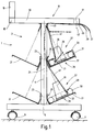
- Figure 1 shows a schematic cross section Work trolley 1, the one composed of rails Has basic body 3.
- the profile rails have a square cross section and a continuous guide groove on each long side on.
- the work trolley 1 is by means of a profile rail 5 of the base body 3 attached roles 7 and 9 movable.
- Perpendicular to the profile rail 5 runs another profile rail 11, on the the rail 5 facing away from an upper end Profile rail 13 is attached such that an I-profile is formed.
- the upper rail 13 are further rails 15 and 17 attached, which in the Extend the image plane of Figure 1 and together with a not shown profile rail limit rectangular storage area 18.
- a carrier 19 is slidably guided, on which, for example, a tool and / or a material shelf, lighting or the like, can be attached.
- On the construction of the work car 1 is based on the figure 2 discussed in more detail.
- a total of four Trays 21 by means of merely indicated fasteners 23 attached, two shelves each on one side of these rails respectively the profile rail 11 arranged one above the other are.
- the other two trays 21 are mirror image of the longitudinal axis 24 of the profile rail arranged on the opposite side.
- the Identically designed shelves 21 are made by folding a rectangular sheet of metal and have an attachment portion 25 which by means of the fastening means 23, for example a screw on which behind the mounting rail 11 arranged profile rail (see profile rail 57 in Figure 2) is attached.
- the shelves 21 are of this type aligned obliquely upwards that one on the Tray 21 loose object, for example a tool or the like, not from this can slide down.
- the top one on the right side of the profile rail 11 arranged shelves 21 is part of a Unwinding device 27 for unwinding windable Material 29 from a roll of material 31, the rests on the shelf 21.
- the material roll 31 is packed in a closed box 33, by on one side in the area of the free diameter the material roll 31 a part under training an opening is removed so that the roll of material 31 from the inside, i.e. based on their free Diameter can be handled.
- a frustoconical, circular guide element 35 formed as a core its larger diameter side into the free diameter of the material roll 31.
- the tray 21 through the carton 33 attracts and adheres to it, causing the between the circulation guide element 35 and the tray 21 Part of the box 33 held clamped becomes.
- the tray 21 and the circulation guide element 35 thus form a magnetic holder 39.
- the Material 29 is made of a tubular one a flexible material existing guide element 41 out. This is with its the roll of material 31 facing away from the fixed to the 11 arranged behind the mounting rail (see profile rails 57, 57 'in FIG. 2) attached baffle 43 connected.
- the material 29 emerges from the Guide element 41 is on the baffle 43 deflected and below the rail 13 in a free pull on one of the guides of the material 29 serving tube 45 led to the bottom the profile rail 17 by means of only indicated fasteners 47 is held.
- To unwind the Roll of material 31 only needs to be at the free end of the material 29 are pulled, whereby this of the material roll 31 is unwound. This prevents that with its movable end on the circulation guide element 35 adjacent guide element 41 a bending or kinking of the material 29 and the formation of loops, which makes it easy Unwinding of the material roll 31 is ensured.
- the lower one on the right side of the profile rail 11 arranged shelves 21 forms together with another circulation guide element 35 a further unwinder 27 for unwinding of material 49 from an unpacked roll of material 51 serves.
- the one having a magnet 37 Circulating guide element 35 adheres to the magnetizable Material existing shelf 21, whereby a magnetic holder 39 is formed.
- FIG. 1 shows the lower shelf 21 assigned a tubular guide element 41, attached to the upper shelf 21 at one end is.
- the material 49 is through the guide element 41 passed and in a free train out to the baffle 43.
- the material 49 is further via the baffle 43 to one in Figure 1 unrecognizable pipe led, like that Tube 45- on the underside of the rail 17 is attached. Materials 29 and 49 can now at the optimal working height by pulling on them free ends in a simple manner from the material rolls 31, 51 are processed.
- Unwinding device 27 is not only limited to a work car. It is also possible, that the unwinder 27 on a fixed Worktable or on a shelf, for example a wall shelf. Independently on the arrangement of the unwinder 27 this is assigned to a circulation guide element 35, the desired unwinding of a material enabled by a roll of material. In one embodiment the unwinding device is provided that this is arranged on a wall shelf and the unwound material over on the ceiling of the Fixed guide elements up to a workplace be performed.
- Figure 2 shows a side view of the work cart 1 in a schematic representation. Parts with those in Figure 1 are the same Provide reference numerals, so that in this respect on their Description with reference to Figure 1 can.
- the work car 1 a plane of symmetry 53.
- On the Bottom of the profile rail 17 are those of the guide of pipes capable of winding materials 45 arranged, the number of which is arbitrary and not the number provided on the work cart 1 Unwinders 27 must correspond.
- the Work trolley 1 also includes profile rails 57 and 57 'which between the rails 11 and 11' are arranged and run parallel to these.
- the shelves 21 are at an end region with its fastening section 25 on the Profile rail 57 and on the other side with the Profile rail 57 'firmly connected.
- the unwinding device 27 also for unwinding so-called Material drums can be used.
- Material drums are understood as material rolls, that are wound on a tube and that of be handled outside.
- the material drum can by means of the magnetic holder 39 attached to the circulation guide element 35 is attached to the shelf 21st be attached and like the "loose" material rolls be handled in the manner described above.
- the magnetic holder 39 enables an optimal adjustment of the unwinder 27 to different rolls of material, creating a easy unwinding of the material from the material roll is possible.
- Through the height adjustment device 55 can be the material of a person in an ergonomic way favorable position are offered that the material by simply pulling on the free one End unwound from the roll of material.
Landscapes
- Warehouses Or Storage Devices (AREA)
- Unwinding Webs (AREA)
- Diaphragms For Electromechanical Transducers (AREA)
- Paper (AREA)
- Controlling Rewinding, Feeding, Winding, Or Abnormalities Of Webs (AREA)
Applications Claiming Priority (2)
| Application Number | Priority Date | Filing Date | Title |
|---|---|---|---|
| DE29704791U DE29704791U1 (de) | 1997-03-15 | 1997-03-15 | Abwickelvorrichtung |
| DE29704791U | 1997-03-15 |
Publications (2)
| Publication Number | Publication Date |
|---|---|
| EP0864281A2 true EP0864281A2 (fr) | 1998-09-16 |
| EP0864281A3 EP0864281A3 (fr) | 1999-11-17 |
Family
ID=8037586
Family Applications (1)
| Application Number | Title | Priority Date | Filing Date |
|---|---|---|---|
| EP98101873A Withdrawn EP0864281A3 (fr) | 1997-03-15 | 1998-02-04 | Dispositif de dévidage |
Country Status (2)
| Country | Link |
|---|---|
| EP (1) | EP0864281A3 (fr) |
| DE (1) | DE29704791U1 (fr) |
Families Citing this family (1)
| Publication number | Priority date | Publication date | Assignee | Title |
|---|---|---|---|---|
| CN110356910B (zh) * | 2019-08-16 | 2024-03-08 | 国网江苏省电力有限公司扬州供电分公司 | 一种集中式布线器 |
Family Cites Families (5)
| Publication number | Priority date | Publication date | Assignee | Title |
|---|---|---|---|---|
| US3396919A (en) * | 1966-03-01 | 1968-08-13 | Gen Cable Corp | Magnetic bobbin holding device |
| DE1760637B2 (de) * | 1968-06-14 | 1976-09-09 | Hamel GmbH, Zwirnmaschinen, 4400 Münster | Doppeldrahtzwirnspindel mit einer aus zwei spulen durch zusammenstecken gebildeten spuleneinheit |
| GB1311264A (en) * | 1971-04-26 | 1973-03-28 | Wirkmaschinenbau Karl Marx Veb | Arrangement for braking the thread running off from a flanged bobbin |
| DE2329831A1 (de) * | 1973-06-12 | 1975-01-09 | Herbert Schuele | Abwickelvorrichtung zum abwickeln von draht oder aehnlichem wickelfaehigem material |
| FR2625755B1 (fr) * | 1988-01-11 | 1990-08-17 | Inst Textile De France | Cantre perfectionne pour metier a tricoter |
-
1997
- 1997-03-15 DE DE29704791U patent/DE29704791U1/de not_active Expired - Lifetime
-
1998
- 1998-02-04 EP EP98101873A patent/EP0864281A3/fr not_active Withdrawn
Also Published As
| Publication number | Publication date |
|---|---|
| DE29704791U1 (de) | 1997-05-07 |
| EP0864281A3 (fr) | 1999-11-17 |
Similar Documents
| Publication | Publication Date | Title |
|---|---|---|
| EP1369211B1 (fr) | Dispositif de guidage et de rappel d'un conduit flexible de robot | |
| DE2949268A1 (de) | Schiebetueranlage | |
| DE3209164A1 (de) | Drahtsaege | |
| DE2522681C2 (de) | Vorrichtung zur Montage von spiralförmig gebogenen Rohren zur Herstellung von rotationssymmetrischen Bauteilen | |
| DE3525292C1 (de) | Kabeltrommelabroller | |
| EP4122858A1 (fr) | Procédé permettant de faire fonctionner un poste de travail d'une machine à bobiner, ainsi que machine à bobiner | |
| DE2628029C2 (de) | Aus Stützenteilen gebildete längenveränderbare Stütze | |
| EP0864281A2 (fr) | Dispositif de dévidage | |
| DE2512619A1 (de) | Seilwinde | |
| DE2624169B2 (de) | Vorrichtung und verfahren zum kontinuierlichen aufwickeln eines drahtes | |
| DE69401704T2 (de) | Zweispurig tzag- und gleiteinrichtung für vorhänge | |
| DE2848304A1 (de) | Vorrichtung zum einfuehren von rohren in rohrboeden oder rohrstuetzwaende | |
| DE9208985U1 (de) | Kabelführungseinrichtung mit zumindest einem Kabelführungsrohr | |
| DE69411489T2 (de) | Ausziehbare Vorrichtung zum Tragen von Objekten, insbesondere Beleuchtungsvorrichtungen von fotografischen Studio und dergleichen | |
| EP0130473A2 (fr) | Dispositif pour le dévidage de fils de bobines dans l'industrie des câbles | |
| DE102015218741B4 (de) | Vorrichtung zum Verstauen von Kabeln | |
| DE29609895U1 (de) | Aufwickelvorrichtung für Kabel zum Anschluß elektrischer Geräte | |
| DE2800098B2 (de) | Abwickelvorrichtung für Warenbahnen in Form von Abwickelrollen | |
| EP0485886B1 (fr) | Utilisation d'un dispositif destiné à recevoir des bobines | |
| DE737307C (de) | Fuehrungsvorrichtung zum Aufwickeln von Faeden, Draehten, Kabeln, Ketten o. dgl. auf umlaufende Spulen oder Trommeln | |
| DE4240663C1 (de) | Spulenhalter für Garnspulen | |
| DE4344218A1 (de) | Abwickelvorrichtung für Wickelgut, insbesondere für Elektro- und Glasfaserkabel | |
| DE8900256U1 (de) | Aufzugsvorrichtung eines freihängenden Vorhanges | |
| DE2911374C2 (de) | Spannvorrichtung | |
| DE19508347A1 (de) | Zuganker für eine Hebevorrichtung |
Legal Events
| Date | Code | Title | Description |
|---|---|---|---|
| PUAI | Public reference made under article 153(3) epc to a published international application that has entered the european phase |
Free format text: ORIGINAL CODE: 0009012 |
|
| AK | Designated contracting states |
Kind code of ref document: A2 Designated state(s): AT BE CH DE DK ES FI FR GB GR IE IT LI LU MC NL PT SE |
|
| PUAL | Search report despatched |
Free format text: ORIGINAL CODE: 0009013 |
|
| AK | Designated contracting states |
Kind code of ref document: A3 Designated state(s): AT BE CH DE DK ES FI FR GB GR IE IT LI LU MC NL PT SE |
|
| AKX | Designation fees paid | ||
| REG | Reference to a national code |
Ref country code: DE Ref legal event code: 8566 |
|
| STAA | Information on the status of an ep patent application or granted ep patent |
Free format text: STATUS: THE APPLICATION IS DEEMED TO BE WITHDRAWN |
|
| 18D | Application deemed to be withdrawn |
Effective date: 20000518 |