EP0864351A2 - Lufttrennung - Google Patents
Lufttrennung Download PDFInfo
- Publication number
- EP0864351A2 EP0864351A2 EP98300805A EP98300805A EP0864351A2 EP 0864351 A2 EP0864351 A2 EP 0864351A2 EP 98300805 A EP98300805 A EP 98300805A EP 98300805 A EP98300805 A EP 98300805A EP 0864351 A2 EP0864351 A2 EP 0864351A2
- Authority
- EP
- European Patent Office
- Prior art keywords
- oxygen
- swing adsorption
- vacuum
- pipeline
- vacuum swing
- Prior art date
- Legal status (The legal status is an assumption and is not a legal conclusion. Google has not performed a legal analysis and makes no representation as to the accuracy of the status listed.)
- Withdrawn
Links
Images
Classifications
-
- B—PERFORMING OPERATIONS; TRANSPORTING
- B01—PHYSICAL OR CHEMICAL PROCESSES OR APPARATUS IN GENERAL
- B01D—SEPARATION
- B01D53/00—Separation of gases or vapours; Recovering vapours of volatile solvents from gases; Chemical or biological purification of waste gases, e.g. engine exhaust gases, smoke, fumes, flue gases, aerosols
- B01D53/02—Separation of gases or vapours; Recovering vapours of volatile solvents from gases; Chemical or biological purification of waste gases, e.g. engine exhaust gases, smoke, fumes, flue gases, aerosols by adsorption, e.g. preparative gas chromatography
- B01D53/04—Separation of gases or vapours; Recovering vapours of volatile solvents from gases; Chemical or biological purification of waste gases, e.g. engine exhaust gases, smoke, fumes, flue gases, aerosols by adsorption, e.g. preparative gas chromatography with stationary adsorbents
- B01D53/047—Pressure swing adsorption
- B01D53/0476—Vacuum pressure swing adsorption
-
- B—PERFORMING OPERATIONS; TRANSPORTING
- B01—PHYSICAL OR CHEMICAL PROCESSES OR APPARATUS IN GENERAL
- B01D—SEPARATION
- B01D2256/00—Main component in the product gas stream after treatment
- B01D2256/12—Oxygen
-
- B—PERFORMING OPERATIONS; TRANSPORTING
- B01—PHYSICAL OR CHEMICAL PROCESSES OR APPARATUS IN GENERAL
- B01D—SEPARATION
- B01D2257/00—Components to be removed
- B01D2257/10—Single element gases other than halogens
- B01D2257/104—Oxygen
-
- B—PERFORMING OPERATIONS; TRANSPORTING
- B01—PHYSICAL OR CHEMICAL PROCESSES OR APPARATUS IN GENERAL
- B01D—SEPARATION
- B01D53/00—Separation of gases or vapours; Recovering vapours of volatile solvents from gases; Chemical or biological purification of waste gases, e.g. engine exhaust gases, smoke, fumes, flue gases, aerosols
- B01D53/02—Separation of gases or vapours; Recovering vapours of volatile solvents from gases; Chemical or biological purification of waste gases, e.g. engine exhaust gases, smoke, fumes, flue gases, aerosols by adsorption, e.g. preparative gas chromatography
- B01D53/04—Separation of gases or vapours; Recovering vapours of volatile solvents from gases; Chemical or biological purification of waste gases, e.g. engine exhaust gases, smoke, fumes, flue gases, aerosols by adsorption, e.g. preparative gas chromatography with stationary adsorbents
- B01D53/0407—Constructional details of adsorbing systems
- B01D53/0446—Means for feeding or distributing gases
Definitions
- This invention relates to air separation.
- it relates to a vacuum swing adsorption method and apparatus for separating an oxygen-enriched gas stream from air.
- Japanese patent application 54-162697A discloses a process in which an oxygen-enriched gas containing 40% by volume of oxygen is separated by means of membranes from air.
- the oxygen-enriched gas is the permeate gas.
- a vacuum is drawn on the permeate gas side of the membranes in order to facilitate the separation of the oxygen-enriched gas.
- the oxygen-enriched gas is supplied to a furnace. Waste heat from the furnace is employed in raising steam.
- the steam flows through an eductor which draws the vacuum.
- Such an arrangement is however unsuitable for practical use because the steam contaminates the oxygen-enriched product. It is therefore necessary to disengage liquid water from the resulting oxygen-enriched gas. It is also necessary to ensure that the steam contains no impurity that might be hazardous in the presence of the oxygen-enriched gas.
- a vacuum swing adsorption method for separating an oxygen-enriched gas stream from air including the step of causing a flow of pressurised steam to draw the vacuum, wherein pressurised steam is raised by heat evolved from an exothermic chemical reaction to which at least some of the oxygen-enriched gas is supplied and in which oxygen is a reactant.
- the invention also provides vacuum swing adsorption apparatus for separating an oxygen-enriched gas stream from air, including a first pipeline for supplying a flow of the oxygen-enriched gas stream to a reactor for performing an exothermic chemical reaction in which oxygen is a reactant, and a second pipeline able to be placed in communication with at least one eductor for causing a flow of pressurised steam to draw the vacuum, wherein the apparatus is associated with a steam generator for raising at least part of the pressurised steam, and means for transferring heat evolved from the reactor to the same or a different steam generator.
- the vacuum swing adsorption method and apparatus according to the invention does not make necessary the use of a steam turbine or gas expansion turbine. Further, because the oxygen-enriched gas stream is not adsorbed, it does not come into contact with the pressurised steam that draws the vacuum and therefore there is no risk of contamination of the oxygen-enriched gas by the steam.
- the steam may be provided at any convenient elevated pressure. Pressures in the range of 5 to 60 bar are generally suitable.
- a source of steam for the eductor or eductors is the steam generator to which said heat is transferred.
- the flow of pressurised steam that draws the vacuum is taken at least in part from the pressurised steam that is raised by heat evolved from the exothermic chemical reaction.
- a part of the pressurised steam may be supplied from a source other than this steam generator.
- the exothermic chemical reaction is typically an oxidation reaction.
- the oxidation reaction typically comprises combustion of a reactant.
- the reactant may be a hydrocarbon fuel. Alternatively, it may be another combustible fluid, for example, ammonia or hydrogen sulphide.
- the reactor comprises a burner which fires into a furnace or kiln. It is typically advantageous to supply the oxygen-enriched gas stream to the burner separately from an air stream or to premix it with the air stream.
- the method and apparatus according to the invention are particularly suited to supplying an oxygen-enriched gas stream to support combustion of part of a hydrogen sulphide stream in a Claus process.
- the oxygen-enriched gas stream is preferably supplied separately from an air stream to a burner which fires into a furnace in which take place combustion of hydrogen sulphide and reaction between resulting sulphur dioxide and residual hydrogen sulphide to form sulphur vapour.
- the source of the pressurised steam supplied to the eductor may be a waste heat boiler associated with the furnace.
- the Claus process is but an example of a process in which the flow of feed fluid varies and therefore the demand for oxygen varies.
- a particular advantage of the method and apparatus according to the invention is that they lend themselves to production of the oxygen-enriched gas stream at a variable flow rate and therefore can readily follow changes in the flow rate of an acid gas stream into the Claus process.
- vacuum swing adsorption apparatus includes a plurality of eductors each connected to the second pipeline and in parallel with one another and one or more first automatically operable on-off valves associated with the eductors arranged and operable so as to select the number of eductors in communication with the second pipeline.
- the vacuum swing adsorption apparatus also includes a plurality of second automatically operable on-off valves each operable to place a different adsorbent bed in communication with the second pipeline, and means for selecting the duration of each period for which one of the second automatically operable on-off valves is open according to the number of eductors that are to communicate with the second pipeline during the said period.
- the vacuum swing adsorption apparatus preferably includes a plurality of adsorbent beds operating out of phase with one another. During each period in which one bed is subjected to a vacuum, another bed receives a flow of air to be separated and preferentially or more rapidly adsorbs nitrogen (in comparison with oxygen). It is desirable in a vacuum swing adsorption apparatus according to the invention to cater for variations in the duration of the periods in which each bed is subjected to the vacuum by making concomitant variations in the flow rate of air into the apparatus (typically by means of a flow control valve in a pipeline for feed air communicating with the apparatus) or preferably by arranging for there to be a dwell period, if necessary, at the end of selected adsorption steps.
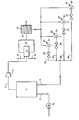
- the illustrated plant includes a vacuum swing adsorption apparatus 2.
- Vacuum swing adsorption is the term applied to pressure swing adsorption in which the minimum desorption pressure that obtains is below atmospheric pressure.
- the vacuum adsorption apparatus 2 may be of any known kind. In this example it is of the kind shown in Figure 1 of US patent 5 122 164 and may operate any one of the cycles illustrated in Figures 2, 3 and 4 of US patent 5 122 164. It should be noted however that the vacuum pump 16 shown in Figure 1 of US patent 5 122 164 is omitted and is replaced by a bank of steam eductors as will be described below.
- the vacuum swing adsorption apparatus 2 has associated therewith a first pipeline 4 for a gaseous oxygen-enriched product gas typically containing at least 90% by volume of oxygen, a second pipeline 6 through which the vacuum is drawn, and a third pipeline 8 through which air is fed into the plant.
- a compressor 10 is located within the first pipeline 4.
- a continuous flow of the oxygen-enriched gas is supplied by the compressor 10 to a burner 12 which fires into a furnace 14 which forms part of a plant for recovering sulphur by the Claus process from a hydrogen sulphide containing gas stream.
- the burner 12 is also supplied with a flow of air via a pipeline 16 and a flow of an acid gas mixture, typically comprising at least 40% by volume of hydrogen sulphide, and typically other combustible gases such as hydrocarbons and ammonia, and also carbon dioxide, a pipeline 18.
- the relative flow of oxygen molecules to hydrogen sulphide and other combustible molecules into the burner 16 is arranged such that a part of the hydrogen sulphide is burnt with the result that sulphur dioxide and water vapour are formed.
- sulphur dioxide reacts in the furnace 14 with residual hydrogen sulphide to form sulphur vapour and water vapour.
- the configuration and operation of the furnace 14 and the burner 12 is substantially as described in EP-A-0 701 967 except that air is supplied to the burner instead of carbon dioxide.
- a gas mixture comprising hydrogen sulphide, sulphur dioxide, water vapour, sulphur vapour, carbon dioxide and nitrogen leaves the furnace 14 through an outlet 20 at a temperature of up to 1650°C.
- the gas mixture flows to a waste heat boiler 22 in which it is cooled and in which steam is raised at an elevated pressure.
- the resulting cooled gas mixture flows through the rest of the Claus plant (not shown in the drawing) which typically comprises the units 14, 16, 18, 20 and 22 shown in Figure 1 of EP-A-0 701 967.
- the reader is referred to EP-A-0 701 967 for further information about these units and their operation.
- At least part of the high pressure steam raised in the waste heat boiler 22 is distributed to a bank of four eductors 24, 26, 28 and 30 arranged in parallel with one another.
- the eductors 24, 26, 28 and 30 have throats 32, 34, 36 and 38, respectively.
- the throats 32, 34, 36 and 38 communicate with conduits 40, 42, 44 and 46, respectively, each of which is connected to the second pipeline 8.
- the conduits 40, 42, 44 and 46 have automatically operable on-off valves 48, 50, 52 and 54, respectively, located therein.
- the vacuum swing adsorption apparatus includes two adsorbent beds A and B in parallel with one another.
- the adsorbent bed A is able to be placed in communication with a source of vacuum by opening the valve 2A, and the adsorbent bed B is similarly able to be placed in communication with the source of vacuum by opening the valve 7B.
- the bed A is subjected to the vacuum drawn in the second pipeline 6 shown in the accompanying drawing.
- the adsorbent bed A is at a pressure substantially above the minimum pressure that obtains in the vacuum swing adsorption process.
- the time taken from opening the valve 2A shown in Figure 1 of US-A-5 122 164 to the achievement of the minimum pressure depends on how many of the valves 48, 50, 52 and 54 are open together.
- valves 48, 50, 52 and 54 are open together, the time taken is at a minimum; if only one is open, the time taken is at a maximum.
- An intermediate time can be achieved by having either two or three of the valves 48, 50, 52 and 54 open together.
- the valve 7B of the apparatus shown in Figure 1 of US-A-5 122 164 is open the bed B is subjected to the vacuum, and the time taken to reach a minimum pressure can be varied by selecting which of the valves 48, 50, 52 and 54 are open.
- the rate of oxygen production can be approximately halved.
- the rate of oxygen production can be turned down in steps or directly by up to about one-half.
- the number of different oxygen supply rates that are possible depends on the number of steam eductors that are used.
- valve controller In order to effect the operation of the valves, 48, 50, 52 and 54 the apparatus shown in the accompanying drawing is provided with a valve controller (not shown). There is typically a single valve controller which in addition to switching the valve 48, 50, 52 and 54 on and off according to a predetermined program also similarly switches on and off all the on-off valves shown in Figure 1 of US-A-5 122 164.
- a flow meter may be located in the acid gas pipeline 18 and arranged to generate a signal representative of the flow rate therethrough. This signal is transmitted to the valve controller which determines which of the valves 48, 50, 52 and 54 are open at any one time.
- the valve controller can respond directly to this change of setting.
- the valve controller may also adjust the operation of the adsorption steps of the vacuum swing adsorption process in concert with adjustment of the bed regeneration steps in which the adsorption beds are subjected to a vacuum. If the time taken from the opening of the valve 2A or 7B shown in Figure 1 of US-A-5 122 164 to the achievement of a minimum pressure is increased by reducing the number of valves 48, 50, 52 and 54 that are open, steps are taken to ensure that impurities do not break through the adsorbent bed during an adsorption step and thereby reduce the purity of the product oxygen-enriched gas to below that specified for it.
- a flow control valve 56 may be located in the feed air pipeline 8 and its setting selected in accordance with the number of the valves 48, 50, 52 and 54 that are open. If there is a reduced number of these valves open, the setting of the flow control valve 56 is chosen so as to reduce the flow rate of air into the vacuum swing adsorption apparatus 2.
- the duration of the adsorption step performed by the left hand, as shown, bed in Figure 2C of US patent 5 122 164 can be adjusted in concert with the duration of the regeneration step performed by the right hand bed.
- the flow control valve 56 may be omitted and the adsorption step permitted to end before the vacuum regeneration step ( Figure 2C of US Patent 5 122 164) when the vacuum swing adsorption apparatus is producing oxygen at a turned down rate.
- the adsorbing bed is isolated from the feed gas and from the product reservoir.
- valves 1 A and 4A are closed.
- the bed A thus dwells in isolation until the end of the regeneration of bed B, whereupon both beds move onto the next step of the vacuum swing adsorption cycle.
- Various means may be employed for sensing when the adsorption step is complete. For example, the oxygen partial pressure in the product pipeline 4 may be monitored, or the pressure in the respective adsorption bed may be monitored.
- the furnace 14 in operating the furnace 14 of the Claus plant, can be operated without any supply of oxygen along the product pipeline unless or until the pressure drop through the plant becomes limiting. Then the flow rate of air along the pipeline 16 is reduced and oxygen is supplied via the pipeline 4. If, for example, the acid gas stream contains less than 40% by volume of combustibles it may, however, be desirable to supply oxygen continuously to the furnace.
- steam may be imported. If desired, a part of the steam may also be imported during normal operation.
- the plant may be specified to produce 60 tonnes per day of sulphur at its maximum output using solely air as the source of oxygen molecules for combustion.
- the vacuum swing adsorption apparatus 2 By operating the vacuum swing adsorption apparatus 2 it is possible to uprate the plant typically to 100 tonnes per day of sulphur, and to supply some 40 to 45% of the oxygen molecules for combustion of the feed gas using steam generated only by the Claus plant itself. There is typically no need at such relative flow rates of oxygen and air into the Claus plant to provide any coolant or quenchant to the interior of the furnace 14 so as to moderate the temperature therein.
- the oxygen supply pressure is typically in the range of 1.5 to 2 bar and the steam is typically supplied to the eductors at a pressure of about 40 bar although lower or higher steam pressures can be used.
- the air feed pipeline 8 may be provided with a blower (not shown) to assist flow of the air.
- the compressor 10 may be omitted and replaced by a compressor (not shown) in the air feed pipeline 8.
- Arrangements may be made to isolate any of the eductors 24, 26, 28 and 30 which for the time being is not being used to evacuate an adsorbent bed from the supply of steam.
- Those of the eductors 24, 26, 28 and 30 that are on line may be arranged to vent their steam to a stack.
- some or all of the steam may be supplied from a source other than the waste heat boiler 22.
- some of the steam may be supplied from one or more sulphur condensers forming part of the Claus plant.
- valves 48, 50, 52 and 54 Another modification that can be made is to omit one of the valves 48, 50, 52 and 54. Accordingly, one eductor is permanently in communication with the second pipeline.
Landscapes
- Chemical & Material Sciences (AREA)
- Engineering & Computer Science (AREA)
- Analytical Chemistry (AREA)
- General Chemical & Material Sciences (AREA)
- Oil, Petroleum & Natural Gas (AREA)
- Chemical Kinetics & Catalysis (AREA)
- Separation Of Gases By Adsorption (AREA)
- Oxygen, Ozone, And Oxides In General (AREA)
Applications Claiming Priority (2)
| Application Number | Priority Date | Filing Date | Title |
|---|---|---|---|
| GB9703959 | 1997-02-26 | ||
| GBGB9703959.8A GB9703959D0 (en) | 1997-02-26 | 1997-02-26 | Air separation |
Publications (2)
| Publication Number | Publication Date |
|---|---|
| EP0864351A2 true EP0864351A2 (de) | 1998-09-16 |
| EP0864351A3 EP0864351A3 (de) | 1998-12-09 |
Family
ID=10808323
Family Applications (1)
| Application Number | Title | Priority Date | Filing Date |
|---|---|---|---|
| EP98300805A Withdrawn EP0864351A3 (de) | 1997-02-26 | 1998-02-04 | Lufttrennung |
Country Status (6)
| Country | Link |
|---|---|
| US (1) | US5989315A (de) |
| EP (1) | EP0864351A3 (de) |
| CN (1) | CN1193097A (de) |
| AU (1) | AU725579B2 (de) |
| CA (1) | CA2227799A1 (de) |
| GB (1) | GB9703959D0 (de) |
Cited By (2)
| Publication number | Priority date | Publication date | Assignee | Title |
|---|---|---|---|---|
| EP1564184A3 (de) * | 2004-02-12 | 2008-05-14 | Honda Motor Co., Ltd. | Vorrichtung zur Herstellung von wasserstoffreichem Brenngas |
| WO2009109290A1 (de) * | 2008-03-05 | 2009-09-11 | Uhde Gmbh | Verfahren und vorrichtung zur abscheidung von fremdgasen aus einem reduzierenden nutzgas durch dampfbetriebene druckwechseladsorption |
Families Citing this family (5)
| Publication number | Priority date | Publication date | Assignee | Title |
|---|---|---|---|---|
| US6708708B2 (en) | 2002-07-25 | 2004-03-23 | The Boeing Company | Pneumatic actuation control system and method of operation |
| US7081153B2 (en) * | 2003-12-02 | 2006-07-25 | Honeywell International Inc. | Gas generating system and method for inerting aircraft fuel tanks |
| US7722698B2 (en) | 2008-02-21 | 2010-05-25 | Delphi Technologies, Inc. | Method of determining the purity of oxygen present in an oxygen-enriched gas produced from an oxygen delivery system |
| US8075676B2 (en) | 2008-02-22 | 2011-12-13 | Oxus America, Inc. | Damping apparatus for scroll compressors for oxygen-generating systems |
| CN114686270A (zh) * | 2022-03-16 | 2022-07-01 | 沈阳铝镁设计研究院有限公司 | 用于提高常压循环流化床气化炉气化剂氧浓度的方法 |
Family Cites Families (17)
| Publication number | Priority date | Publication date | Assignee | Title |
|---|---|---|---|---|
| US2273350A (en) * | 1940-08-07 | 1942-02-17 | Socony Vacuum Oil Co Inc | Method of handling dehydration |
| US2747681A (en) * | 1951-09-05 | 1956-05-29 | British Oxygen Co Ltd | Regeneration of adsorbent units |
| US2773774A (en) * | 1953-09-22 | 1956-12-11 | Nat Engineering & Dev Corp | Concentration of fruit juices |
| US3691728A (en) * | 1969-10-29 | 1972-09-19 | Phillips Petroleum Co | Regeneration process for solid desiccants |
| US3696588A (en) * | 1970-12-07 | 1972-10-10 | Ingersoll Rand Co | Gas drying apparatus and method |
| GB1433416A (en) * | 1973-07-26 | 1976-04-28 | British Petroleum Co | Hydrocarbon separation process |
| US3899684A (en) * | 1974-06-03 | 1975-08-12 | Ozone Inc | Control system for corona discharge ozone generating unit |
| JPS5827480B2 (ja) * | 1979-02-14 | 1983-06-09 | 株式会社日立製作所 | 希ガスホ−ルドアツプ装置の脱湿塔再生方法 |
| DE2906057A1 (de) * | 1979-02-16 | 1980-08-28 | Linde Ag | Druckwechseladsorptionsverfahren zur zerlegung oder reinigung von gasgemischen |
| US4331456A (en) * | 1979-06-08 | 1982-05-25 | John Zink Company | Process for recovering hydrocarbons with air-hydrocarbon vapor mixtures |
| US4425142A (en) * | 1982-11-15 | 1984-01-10 | Chicago Bridge & Iron Company | Pressure swing adsorption cycle for natural gas pretreatment for liquefaction |
| JPS60191002A (ja) * | 1984-03-07 | 1985-09-28 | Osaka Oxgen Ind Ltd | 吸着法を使用して少なくとも水素を含む混合ガス中の水素を濃縮する方法 |
| US4813977A (en) * | 1987-12-29 | 1989-03-21 | Air Products And Chemicals, Inc. | Adsorptive nitrogen generation utilizing multiple adsorption beds |
| DE69124276T2 (de) * | 1990-03-29 | 1997-05-07 | Boc Group Inc | Verfahren zur Herstellung eines mit Sauerstoff angereicherten Produktstroms |
| FR2663625B1 (fr) * | 1990-06-25 | 1992-09-11 | Air Liquide | Procede et installation d'elaboration d'hydrogene pur. |
| US5203888A (en) * | 1990-11-23 | 1993-04-20 | Uop | Pressure swing adsorption process with multiple desorption steps |
| JPH0593519A (ja) * | 1991-04-02 | 1993-04-16 | Mitsubishi Heavy Ind Ltd | ガス化複合発電プラント |
-
1997
- 1997-02-26 GB GBGB9703959.8A patent/GB9703959D0/en active Pending
-
1998
- 1998-01-26 CA CA002227799A patent/CA2227799A1/en not_active Abandoned
- 1998-02-04 EP EP98300805A patent/EP0864351A3/de not_active Withdrawn
- 1998-02-05 US US09/019,399 patent/US5989315A/en not_active Expired - Fee Related
- 1998-02-10 AU AU53872/98A patent/AU725579B2/en not_active Ceased
- 1998-02-26 CN CN98105950A patent/CN1193097A/zh active Pending
Cited By (5)
| Publication number | Priority date | Publication date | Assignee | Title |
|---|---|---|---|---|
| EP1564184A3 (de) * | 2004-02-12 | 2008-05-14 | Honda Motor Co., Ltd. | Vorrichtung zur Herstellung von wasserstoffreichem Brenngas |
| US7427304B2 (en) | 2004-02-12 | 2008-09-23 | Honda Motor Co., Ltd. | Fuel gas manufacturing apparatus |
| WO2009109290A1 (de) * | 2008-03-05 | 2009-09-11 | Uhde Gmbh | Verfahren und vorrichtung zur abscheidung von fremdgasen aus einem reduzierenden nutzgas durch dampfbetriebene druckwechseladsorption |
| US8361198B2 (en) | 2008-03-05 | 2013-01-29 | Uhde Gmbh | Process and device for the separation of foreign gases from a reducing useful gas by steam-driven pressure swing adsorption |
| EA017672B1 (ru) * | 2008-03-05 | 2013-02-28 | Уде Гмбх | Способ и устройство для отделения примесных газов от восстановительного рабочего газа посредством работающей на паре адсорбции при перемежающемся давлении |
Also Published As
| Publication number | Publication date |
|---|---|
| US5989315A (en) | 1999-11-23 |
| CN1193097A (zh) | 1998-09-16 |
| AU5387298A (en) | 1998-09-03 |
| CA2227799A1 (en) | 1998-08-26 |
| AU725579B2 (en) | 2000-10-12 |
| GB9703959D0 (en) | 1997-04-16 |
| EP0864351A3 (de) | 1998-12-09 |
Similar Documents
| Publication | Publication Date | Title |
|---|---|---|
| EP3728112B1 (de) | Verfahren zur herstellung eines wasserstoffhaltigen synthesegases | |
| RU2166546C1 (ru) | Способ объединения доменной печи и реактора прямого восстановления с использованием криогенной ректификации | |
| KR20010032208A (ko) | 산소선택성 이온전달막을 장착한 열로 가동되는 산소/질소발생장치 | |
| EP2004307A1 (de) | Verfahren zur kohlenstoffoxid- und wasserstofferzeugung aus synthesegas | |
| KR101353476B1 (ko) | 수소 제조 시스템 및 해당 시스템에 있어서의 오프가스의 유량 제어 방법 | |
| WO2007021911A2 (en) | Synthesis gas and carbon dioxide generation method | |
| JPS63296820A (ja) | 高純度水素又はヘリウムの製造方法 | |
| CA2716781A1 (en) | Process and device for the separation of foreign gases from a reducing useful gas by steam-driven pressure swing adsorption | |
| JP7770165B2 (ja) | 水素製造方法及び水素製造設備 | |
| KR100526232B1 (ko) | 재생기와 세라믹 막을 이용한 가스의 분리 방법 | |
| US5989315A (en) | Air separation | |
| AU2022407314B2 (en) | Ammonia cracking process and apparatus for improved hydrogen recovery | |
| JP3302363B2 (ja) | 高純度一酸化炭素の製造方法 | |
| JPH08333106A (ja) | 熱処理用窒素を発生する方法及び装置 | |
| US5985006A (en) | Gas separation | |
| JPH06212251A (ja) | 熱処理雰囲気の形成方法 | |
| US6607582B2 (en) | Method of feeding, with impure nitrogen, the combustion chamber of a gas turbine combined with an air distillation unit, and corresponding electricity generation plant | |
| Kumar et al. | Gas mixture fractionation to produce two high purity products by pressure swing adsorption | |
| JP2002355522A (ja) | 水素精製用4塔式psa装置におけるオフガスタンクからのオフガス圧力の制御方法 | |
| MXPA98001379A (en) | Separation of a | |
| JP6602941B1 (ja) | 水素製造装置及び水素製造方法 | |
| JP2002355519A (ja) | 水素精製用4塔式圧力スイング吸着装置の安定運転方法 | |
| MXPA98001378A (en) | Separation of | |
| JPH04240101A (ja) | メタノールからの水素製造設備での二酸化炭素製造方法 | |
| JPH02182824A (ja) | 窒素雰囲気熱処理装置 |
Legal Events
| Date | Code | Title | Description |
|---|---|---|---|
| PUAI | Public reference made under article 153(3) epc to a published international application that has entered the european phase |
Free format text: ORIGINAL CODE: 0009012 |
|
| AK | Designated contracting states |
Kind code of ref document: A2 Designated state(s): DE FR GB |
|
| AX | Request for extension of the european patent |
Free format text: AL;LT;LV;MK;RO;SI |
|
| PUAL | Search report despatched |
Free format text: ORIGINAL CODE: 0009013 |
|
| AK | Designated contracting states |
Kind code of ref document: A3 Designated state(s): AT BE CH DE DK ES FI FR GB GR IE IT LI LU MC NL PT SE |
|
| AX | Request for extension of the european patent |
Free format text: AL;LT;LV;MK;RO;SI |
|
| 17P | Request for examination filed |
Effective date: 19990608 |
|
| AKX | Designation fees paid |
Free format text: DE FR GB |
|
| 17Q | First examination report despatched |
Effective date: 20010611 |
|
| STAA | Information on the status of an ep patent application or granted ep patent |
Free format text: STATUS: THE APPLICATION IS DEEMED TO BE WITHDRAWN |
|
| 18D | Application deemed to be withdrawn |
Effective date: 20011222 |