EP0864372A2 - Behälter zur Abgabe von Tröpfen - Google Patents
Behälter zur Abgabe von Tröpfen Download PDFInfo
- Publication number
- EP0864372A2 EP0864372A2 EP98104467A EP98104467A EP0864372A2 EP 0864372 A2 EP0864372 A2 EP 0864372A2 EP 98104467 A EP98104467 A EP 98104467A EP 98104467 A EP98104467 A EP 98104467A EP 0864372 A2 EP0864372 A2 EP 0864372A2
- Authority
- EP
- European Patent Office
- Prior art keywords
- dropping
- opening
- cylindrical body
- pressure valve
- sealing plug
- Prior art date
- Legal status (The legal status is an assumption and is not a legal conclusion. Google has not performed a legal analysis and makes no representation as to the accuracy of the status listed.)
- Granted
Links
- 238000007789 sealing Methods 0.000 claims abstract description 45
- 125000006850 spacer group Chemical group 0.000 claims description 16
- 239000010935 stainless steel Substances 0.000 claims description 7
- 229910001220 stainless steel Inorganic materials 0.000 claims description 7
- 229920003051 synthetic elastomer Polymers 0.000 claims description 5
- 239000005061 synthetic rubber Substances 0.000 claims description 5
- 229920003052 natural elastomer Polymers 0.000 claims description 4
- 229920001194 natural rubber Polymers 0.000 claims description 4
- 229910044991 metal oxide Inorganic materials 0.000 claims description 3
- 150000004706 metal oxides Chemical class 0.000 claims description 3
- 229920005672 polyolefin resin Polymers 0.000 claims description 2
- 239000000126 substance Substances 0.000 abstract description 18
- 230000000694 effects Effects 0.000 abstract description 4
- 238000004321 preservation Methods 0.000 abstract description 2
- 239000000463 material Substances 0.000 description 15
- 239000003795 chemical substances by application Substances 0.000 description 13
- PXHVJJICTQNCMI-UHFFFAOYSA-N Nickel Chemical compound [Ni] PXHVJJICTQNCMI-UHFFFAOYSA-N 0.000 description 10
- 239000002184 metal Substances 0.000 description 10
- 229910052751 metal Inorganic materials 0.000 description 10
- 239000007788 liquid Substances 0.000 description 9
- 229910001369 Brass Inorganic materials 0.000 description 6
- 239000010951 brass Substances 0.000 description 6
- 238000010586 diagram Methods 0.000 description 6
- 229920001973 fluoroelastomer Polymers 0.000 description 6
- 239000003708 ampul Substances 0.000 description 5
- 239000011521 glass Substances 0.000 description 5
- 229910052759 nickel Inorganic materials 0.000 description 5
- 239000000057 synthetic resin Substances 0.000 description 5
- 229920003002 synthetic resin Polymers 0.000 description 5
- XEEYBQQBJWHFJM-UHFFFAOYSA-N Iron Chemical compound [Fe] XEEYBQQBJWHFJM-UHFFFAOYSA-N 0.000 description 4
- 239000000853 adhesive Substances 0.000 description 4
- 230000001070 adhesive effect Effects 0.000 description 4
- -1 polyethylene Polymers 0.000 description 4
- 230000006866 deterioration Effects 0.000 description 3
- 238000010068 moulding (rubber) Methods 0.000 description 3
- 229920005989 resin Polymers 0.000 description 3
- 239000011347 resin Substances 0.000 description 3
- CSCPPACGZOOCGX-UHFFFAOYSA-N Acetone Chemical compound CC(C)=O CSCPPACGZOOCGX-UHFFFAOYSA-N 0.000 description 2
- 239000004698 Polyethylene Substances 0.000 description 2
- 239000004743 Polypropylene Substances 0.000 description 2
- 239000004809 Teflon Substances 0.000 description 2
- 229920006362 Teflon® Polymers 0.000 description 2
- QVGXLLKOCUKJST-UHFFFAOYSA-N atomic oxygen Chemical compound [O] QVGXLLKOCUKJST-UHFFFAOYSA-N 0.000 description 2
- 230000007547 defect Effects 0.000 description 2
- 229920001971 elastomer Polymers 0.000 description 2
- 229910052742 iron Inorganic materials 0.000 description 2
- 150000002739 metals Chemical class 0.000 description 2
- 229910052760 oxygen Inorganic materials 0.000 description 2
- 239000001301 oxygen Substances 0.000 description 2
- 229920000573 polyethylene Polymers 0.000 description 2
- 229920001155 polypropylene Polymers 0.000 description 2
- 239000005060 rubber Substances 0.000 description 2
- 229920001187 thermosetting polymer Polymers 0.000 description 2
- 239000004925 Acrylic resin Substances 0.000 description 1
- 229920000178 Acrylic resin Polymers 0.000 description 1
- 229920002449 FKM Polymers 0.000 description 1
- 244000043261 Hevea brasiliensis Species 0.000 description 1
- JHWNWJKBPDFINM-UHFFFAOYSA-N Laurolactam Chemical compound O=C1CCCCCCCCCCCN1 JHWNWJKBPDFINM-UHFFFAOYSA-N 0.000 description 1
- 239000004677 Nylon Substances 0.000 description 1
- 229920000299 Nylon 12 Polymers 0.000 description 1
- 229910052581 Si3N4 Inorganic materials 0.000 description 1
- VYPSYNLAJGMNEJ-UHFFFAOYSA-N Silicium dioxide Chemical compound O=[Si]=O VYPSYNLAJGMNEJ-UHFFFAOYSA-N 0.000 description 1
- XUIMIQQOPSSXEZ-UHFFFAOYSA-N Silicon Chemical compound [Si] XUIMIQQOPSSXEZ-UHFFFAOYSA-N 0.000 description 1
- PNEYBMLMFCGWSK-UHFFFAOYSA-N aluminium oxide Inorganic materials [O-2].[O-2].[O-2].[Al+3].[Al+3] PNEYBMLMFCGWSK-UHFFFAOYSA-N 0.000 description 1
- 210000000988 bone and bone Anatomy 0.000 description 1
- 230000015556 catabolic process Effects 0.000 description 1
- 230000002542 deteriorative effect Effects 0.000 description 1
- 239000000945 filler Substances 0.000 description 1
- 239000003517 fume Substances 0.000 description 1
- 238000004519 manufacturing process Methods 0.000 description 1
- 229920001778 nylon Polymers 0.000 description 1
- RVTZCBVAJQQJTK-UHFFFAOYSA-N oxygen(2-);zirconium(4+) Chemical compound [O-2].[O-2].[Zr+4] RVTZCBVAJQQJTK-UHFFFAOYSA-N 0.000 description 1
- 239000004033 plastic Substances 0.000 description 1
- 229920003023 plastic Polymers 0.000 description 1
- 229920003217 poly(methylsilsesquioxane) Polymers 0.000 description 1
- 229920000098 polyolefin Polymers 0.000 description 1
- 229910001750 ruby Inorganic materials 0.000 description 1
- 239000010979 ruby Substances 0.000 description 1
- 229910052710 silicon Inorganic materials 0.000 description 1
- 239000010703 silicon Substances 0.000 description 1
- HQVNEWCFYHHQES-UHFFFAOYSA-N silicon nitride Chemical compound N12[Si]34N5[Si]62N3[Si]51N64 HQVNEWCFYHHQES-UHFFFAOYSA-N 0.000 description 1
- 229910052814 silicon oxide Inorganic materials 0.000 description 1
- 229920002379 silicone rubber Polymers 0.000 description 1
- 239000002904 solvent Substances 0.000 description 1
- 229920002803 thermoplastic polyurethane Polymers 0.000 description 1
- 239000012780 transparent material Substances 0.000 description 1
- CMHHITPYCHHOGT-UHFFFAOYSA-N tributylborane Chemical compound CCCCB(CCCC)CCCC CMHHITPYCHHOGT-UHFFFAOYSA-N 0.000 description 1
- 229910001928 zirconium oxide Inorganic materials 0.000 description 1
Images


Classifications
-
- B—PERFORMING OPERATIONS; TRANSPORTING
- B05—SPRAYING OR ATOMISING IN GENERAL; APPLYING FLUENT MATERIALS TO SURFACES, IN GENERAL
- B05C—APPARATUS FOR APPLYING FLUENT MATERIALS TO SURFACES, IN GENERAL
- B05C17/00—Hand tools or apparatus using hand held tools, for applying liquids or other fluent materials to, for spreading applied liquids or other fluent materials on, or for partially removing applied liquids or other fluent materials from, surfaces
- B05C17/005—Hand tools or apparatus using hand held tools, for applying liquids or other fluent materials to, for spreading applied liquids or other fluent materials on, or for partially removing applied liquids or other fluent materials from, surfaces for discharging material from a reservoir or container located in or on the hand tool through an outlet orifice by pressure without using surface contacting members like pads or brushes
- B05C17/01—Hand tools or apparatus using hand held tools, for applying liquids or other fluent materials to, for spreading applied liquids or other fluent materials on, or for partially removing applied liquids or other fluent materials from, surfaces for discharging material from a reservoir or container located in or on the hand tool through an outlet orifice by pressure without using surface contacting members like pads or brushes with manually mechanically or electrically actuated piston or the like
Definitions
- the present invention relates to a dropping container and, more specifically, to a dropping container for containing an unstable substance which reacts, decomposes or fumes when it contacts air and for dropping the substance upon use.
- Japanese Patent Publication No. 42-12318 (12,318/1967) discloses that an acrylic resin adhesive comprising alkylboron as a curing agent shows strong adhesion to a bone and a tooth and is useful for dental and surgical applications.
- alkylboron used as a curing agent is an unstable substance which readily reacts with oxygen in the air and loses its activity thereby.
- a curing agent which overcomes this defect is disclosed by Japanese Patent Publication No. 51-37092 (37,092/1976).
- Japanese Patent Publication No. 51-37092 discloses an adhesive filler for dental and surgical applications which comprises a product obtained by reacting trialkylboron with 0.3 to 0.9 mol of oxygen as a curing agent.
- the product as a curing agent is used to suppress the adhesion of trialkylboron to the least possible degree so as to remove the ignitability of the trialkylboron.
- this product is also an unstable substance, though not so unstable as trialkylboron.
- Japanese Laid-open Utility Model Application No. 50-139498 discloses a dropping container in which a closing portion having a thin tube for dropping is provided at one end of a cylindrical body made from a metal or glass and a movable plug made from fluororubber or fluororesin is provided near the other end, and the movable plug is pushed by rotating a screw attached to the cylindrical body or a container for mounting the cylindrical body to take out a predetermined amount of a curing agent filled in the cylindrical body.
- This container enables a required amount of alkylboron to be taken out by dropping.
- a curing agent present in the thin tube for dropping contacts the outside air through an opening at the tip of the thin tube, it is almost impossible to prevent the curing agent from deteriorating gradually even with the tip capped when it is preserved for a long time.
- Japanese Laid-open Utility Model Application No. 5-65900 discloses a dropping container having such a structure that entry of air from the outside can be inhibited almost perfectly to prevent the deterioration of a curing agent when it is preserved for a long time.
- this dropping container has such a structure that it is sealed up by an elastic body itself to preserve a chemical, the elastic body may deteriorate due to the chemical through its long-time use.
- a dropping container which comprises a pressure valve for closing an opening in a dropping container body so that it can be opened by pressure, the pressure valve comprising a sealing plug portion formed of an elastic body or a rigid body and a pressing member, formed of an elastic body, for pressing the sealing plug portion against the opening to close the opening.
- the dropping container of the present invention comprises a pressure valve and a dropping portion having a thin tube which is open to the outside, as described above.
- the pressure valve has a sealing plug portion formed of an elastic body or a rigid body.
- the pressure valve closes an opening in the dropping container body with the sealing plug portion such that it can be opened by pressure.
- a substance to be dropped filled in the dropping container body such as alkylboron as described above, is dropped from the dropping container through the opened opening and then the thin tube which is open to the outside.
- the sealing plug portion of the pressure valve is formed of an elastic body or a rigid body as described above.
- the elastic body include natural rubber and synthetic rubber and illustrative examples of the rigid body include fluororesin, stainless steel, polyolefin resins and metal oxides.
- the opening in the dropping container body and the sealing plug portion of the pressure valve are preferably in surface contact or circular line contact with each other to close the opening.
- the dropping container of the present invention preferably further is provided with a spacer in space for accommodating the above sealing plug portion and pressing member, that is, pressure valve, to reduce dead space in the space.
- the spacer may be integrated with the sealing plug portion of the pressure valve.
- the sealing plug portion of the pressure valve may also be integrated with the pressing member.
- the above pressing member is formed of an elastic body.
- the pressing member may be formed of, for example, a coil spring, a flat spring or an elastic body such as natural or synthetic rubber.
- the pressing member works to press the sealing plug portion against the opening to close the opening in the dropping container body.
- the content of the cylindrical body is pressed by the movable plug, enters the dropping portion by opening the pressure valve and is dropped through the thin tube which is open to the outside.
- the inner diameter of the thin tube is suitably determined by the weight (or volume) of one drop required, the viscosity of the content, or the like, while it is generally about 0.1 to 3 mm.
- the length of the thin tube is also suitably selected as required, while it is generally about 1 to 20 mm.
- the thin tube is made from, for example, iron plated with nickel.
- a dropping container comprising:
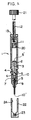
- Fig. 1 is a schematic sectional view for explaining the structure of the dropping container of the present invention.
- Reference numeral (1) denotes a cylindrical body, (2) the first closing portion, (3) the first thin tube, (4) a projecting portion, (5) and (5') openings, (6) a sealing plug portion of a pressure valve, (7) a pressing member of the pressure valve, (8) the second thin tube, (9) a dropping portion, (10) and (10') openings, (11) a movable plug, (12) pressing means and (13) the second closing portion.
- the cylindrical body (1) is made from, for example, glass, a suitable synthetic resin or metal. These materials are required to have the following properties. That is, (i) it must not change the quality of the content, (ii) it must be hardly damaged at the time of production, and (iii) it must be transparent so that content can be seen. Therefore, the cylindrical body (1) is preferably made from a transparent material, particularly preferably transparent glass.
- the first closing portion (2) closes one end of the cylindrical body (1).
- the cylindrical body (1) and the first closing portion (2) can be fixed by, for example, a thermosetting resin-based adhesive.
- the first closing portion (2) is preferably made from a metal such as brass plated with nickel.
- the first closing portion (2) has the first thin tube (3) extending therethrough.
- the first thin tube (3) may be integrated with the first closing portion (2) or may be fixed to the first closing portion (2) as a part separate from the first closing portion (2).
- the first closing portion (2) has the projecting portion (4) which projects from the cylindrical body (1) toward the axial direction of the cylindrical body (1).
- the first closing portion (2) and the projecting portion (4) have the first thin tube (3) extending therethrough, and the first thin tube (3) has the opening (5) at one end thereof at the tip in a longitudinal direction of the projecting portion (4) and the opening (5') at the other end in the first closing portion (2) within the cylindrical body (1).
- the projecting portion (4) has the opening (5) of the first thin tube (3) at the tip in a longitudinal direction.
- the openings (5') and (5) serve as an inlet and outlet for taking out a filling material filled in the cylindrical body (1) through the first thin tube (3), respectively.
- the opening (5) is preferably a tapered opening.
- the projecting portion (4) of the first thin tube (3) is mated with the dropping portion (9) having the second thin tube (8). Inside the dropping portion (9), there is space between the projecting portion (4) and the second thin tube.
- the pressure valve comprising the sealing plug portion (6) formed of an elastic body or a rigid body and the pressing member (7) formed of an elastic body lies in this space.
- the sealing plug portion (6) of the pressure valve is pressed in a fully liquid-filled state against the opening of the dropping container body, that is, the opening (5) of the first thin tube (3), to close the opening (5).
- a spacer may be provided in the space to reduce dead space.
- the sealing plug portion (14) has such a shape that it can contact the opening (5) in a fully liquid-filled state such as a spherical shape, semi-spherical shape, spherical or semi-spherical shape having a dented top portion.
- the tapered portion of the opening (5) and the sealing plug portion are pressed against each other in a fully liquid-filled state by circular line contact.
- a sealing plug portion having a circular or square top surface as shown in Fig. 5 or Fig. 6 may be used. These sealing plug portions are pressed against the opening in a fully liquid-filled state by surface contact. Further, the opening (5) may be structured such that liquid-tightness can be maintained on a concave or convex surface. Out of these, circular line contact is preferred.
- the material of the sealing plug portion (14) is selected from metals such as 18-8 stainless steel, metal oxides such as ruby, alumina oxide, zirconium oxide, silicon nitride, silicon oxide and glass, and synthetic resins such as polyethylene, polypropylene, nylon and fluororesin. Out of these, a material which does not react with the content and does not swell is suitably selected and used.
- the elastic body has a function to press the sealing plug portion against the opening (5) in the space and can be, for example, a coil spring, a flat spring or rubber molding. Out of these, a coil spring and flat spring are preferred.
- the coil spring or flat spring is preferably made from a metal such as stainless steel or brass, and the rubber molding is preferably made from a synthetic resin such as fluororubber or silicon. Sealability can be adjusted by changing the diameter of a spring wire material.
- the spacer is a means of reducing a volume other than a volume occupied by the sealing plug portion and the elastic body within the space of the dropping portion as much as possible.
- the spacer can exist in the space as a member independent of the sealing plug portion and the elastic body, or may be integrated with the sealing plug portion or the elastic body. In either case, the spacer must not prevent the sealing plug portion from being pressed against the opening in a fully liquid-filled state or the elastic body from acting on the sealing plug portion.
- the spacer (19) is connected to the sealing plug portion (17) at a position where it does not prevent the sealing plug portion (17) from contacting the opening.
- the elastic body is indicated by (18).
- the material of the spacer is selected from metals such as stainless steel and brass, synthetic rubber such as fluororubber and silicon rubber, polyolefins such as polyethylene and polypropylene and synthetic resins such as fluororesin and urethane resin.
- the spacer formed of a metal or a rubber molding is cylindrical, for example.
- the cylinder has cutouts or holes in the side surface so that the inside and outside of the side surface of the cylinder are communicated with each other through the cutouts and holes.
- the spacer is preferably situated on the inner side of the elastic body within the space of the dropping portion.
- the dropping portion (9) has the second thin tube (8).
- the dropping portion (9) encases the projecting portion (4) and the pressure valve, that is, the sealing plug portion (6) and the pressing member (7), and is fitted to, or joined to, the projecting portion (4).
- the opening (10) at one end of the second thin tube (8) is open to the inside of the dropping portion (9) and the opening (10') at the other end of the second thin tube (8) is open to the outside.
- the dropping portion (9) can be made from a metal such as brass plated with nickel, and the second thin tube (8) can be a metal pipe such as a stainless steel pipe.
- the second thin tube (8) of the dropping portion (9) penetrates the dropping portion (9) so that the interior space of the dropping portion (9) communicates with the outside air therethrough.
- the second thin tube (8) and the dropping portion (9) can be produced as an integrated unit or separate units. In the latter case, the second thin tube (8) is inserted into a small hole formed in the center of the dropping portion (9) and fixed to the dropping portion (9) by caulking, for example.
- the dropping container of the present invention has a movable plug (11) which can move in an axial direction in the cylindrical body (1).
- the material of the movable plug (11) is suitably selected from plastics and rubber which do not undergo change in qualities by the chemicals, that is, have chemical stability and dimensional stability and which can move along the inner wall of the cylindrical body in a fully liquid-filled state.
- fluororubber and fluororesin are preferred.
- the fluororesin is a resin having relatively high lubricity, it has poor elasticity. Therefore, as shown in Fig. 1, it is advantageous to form one or more annular grooves (20) in the movable plug (11).
- the annular groove may be fitted with a fluororubber-based O ring such as Kalrez or Viton as required.
- the movable plug (11) is pressed and moved toward the direction of the closing portion (2) by the pressing means (12) provided in the second closing portion (13) fixed at the other end of the cylindrical body (1).
- the filling material filled in the cylindrical body is pressed forward by this movement, whereby the pressure valve (6) pressing the opening (5) is slightly opened.
- the filling material moves into space between the projecting portion (4) and the second thin tube (8) and is then dropped from the opening (10') at the end of the second thin tube (8).
- the second closing portion (13) can be made from a metal, preferably brass plated with nickel.
- the second closing portion (13) is fixed at the other end of the cylindrical body (1) by a thermosetting resin-based adhesive.
- the pressing means (12) provided in the second closing portion (13) can be a screw or a piston, for example (screw in Fig. 1).
- the screw (12) turns and moves forward in a threaded portion formed in the center of the second closing portion (13), comes into contact with the movable plug (11) (does not contact in the Fig. 1) and presses the movable plug (11).
- the screw (12) can be driven by turning a knob (21) manually.
- the dropping container of the present invention can have a cap (22) for covering a top end portion of the container.
- the cap (22) can be made from a synthetic resin such as Nylon 12.
- the cap (22) preferably has a rubber presser foot, for example, a fluororubber presser foot (23) at a position where it contacts the tip of the second thin tube (8) when it covers the top end portion of the dropping container.
- the cap (22) can have an annular projection (24) which projects toward the inside of the cylindrical body (1) and the annular projection (24) allows to fix the cap (22) on the periphery of the dropping portion (9) detachably.
- the pressure valve (6) is pressed against the opening (5) in the projecting portion (4) of the first thin tube (3) extending from the cylindrical body (1) to shut off the outside air completely from the filling material in the cylindrical body when not in use. Therefore, the deterioration of the filling material through its contact with the outside air can be prevented when it is preserved.
- the pressure valve comprising the sealing plug portion, the elastic body and as required, the spacer, lies in the space of the dropping portion between the projecting portion (4) and the second thin tube (8), dead space can be made extremely small. Therefore, even if the filling material in the dead space deteriorates while it is preserved, in spite of the use of the cap, the amount of the deteriorated filling material is small and the further deterioration of the filling material can be prevented completely.
- the dropping container of the present invention can be exemplified by a syringe comprising a cylindrical body formed of a hard glass tube having an inner diameter of 5 mm, an outer diameter of 8 mm and a length of 70 mm; the first thin tube made from brass and having an inner diameter of 1 mm; the second thin tube of the dropping portion made from iron plated with nickel and having an inner diameter of 0.3 mm and a connection portion having a length from the end of the second thin tube to the cylindrical body of about 20 mm (a portion of the thin tube projecting forward from the dropping portion being about 6 mm); a screw having a diameter of 3 mm; a knob having a diameter of 10 mm; the spring of a spacer 7''' made from an elastic wire material having a diameter of 0.4 mm; and a cap having an outer diameter of 8 mm and a length of about 22 mm.
- the size of the dropping container is not limited to the size of this example. However, it has been found that the dropping container of this size in the
- a partial oxide of tributylboron containing about 30 wt% of acetone was dropped from the above dropping container comprising a Teflon R ball (fluororesin having a diameter of 1/8 inch) as the sealing member (14). Dropping could be carried out smoothly. There was no liquid leakage after use.
- Example 2 Dropping was carried out in the same manner as in Example 1 except that a 18-8 stainless steel ball (diameter of 1/8 inch) was used in place of the Teflon R ball. Dropping could be carried out smoothly. Leakage of a trace amount of a solution occurred after use but stopped immediately.
- the dropping container of the present invention perfectly prevents entry of air from the outside, has small dead space and can drop a required amount of a chemical easily. Therefore, the dropping container of the present invention does not deteriorate a liquid chemical substance which is filled in the container and deteriorates upon its contact with the outside air even when it is preserved for a long time.
Landscapes
- Engineering & Computer Science (AREA)
- Mechanical Engineering (AREA)
- Closures For Containers (AREA)
- Medical Preparation Storing Or Oral Administration Devices (AREA)
Applications Claiming Priority (3)
| Application Number | Priority Date | Filing Date | Title |
|---|---|---|---|
| JP61057/97 | 1997-03-14 | ||
| JP6105797 | 1997-03-14 | ||
| JP6105797 | 1997-03-14 |
Publications (3)
| Publication Number | Publication Date |
|---|---|
| EP0864372A2 true EP0864372A2 (de) | 1998-09-16 |
| EP0864372A3 EP0864372A3 (de) | 1999-06-16 |
| EP0864372B1 EP0864372B1 (de) | 2002-12-04 |
Family
ID=13160188
Family Applications (1)
| Application Number | Title | Priority Date | Filing Date |
|---|---|---|---|
| EP98104467A Expired - Lifetime EP0864372B1 (de) | 1997-03-14 | 1998-03-12 | Behälter zur Abgabe von Tröpfen |
Country Status (3)
| Country | Link |
|---|---|
| US (1) | US6109484A (de) |
| EP (1) | EP0864372B1 (de) |
| DE (1) | DE69809822T2 (de) |
Cited By (1)
| Publication number | Priority date | Publication date | Assignee | Title |
|---|---|---|---|---|
| CN101118307B (zh) * | 2006-08-04 | 2010-09-29 | 鸿富锦精密工业(深圳)有限公司 | 点胶装置 |
Families Citing this family (9)
| Publication number | Priority date | Publication date | Assignee | Title |
|---|---|---|---|---|
| US6655607B2 (en) * | 2000-04-06 | 2003-12-02 | Eduardo Vazquez | Spray can adaptor |
| WO2003082931A1 (en) * | 2002-03-28 | 2003-10-09 | Sun Medical Co., Ltd. | Paste polymerization initiator composition, dental or surgical adhesive and adhesive kit |
| DE10326706A1 (de) * | 2003-06-04 | 2005-01-05 | Schott Ag | Spritze, insbesondere für medizinische Anwendungen, sowie Verfahren zum Herstellen einer solchen |
| DE10327182B4 (de) * | 2003-06-17 | 2009-07-02 | Holger Nerlich | Dosierstift |
| US7261559B2 (en) * | 2005-04-01 | 2007-08-28 | Ultradent Products, Inc. | Syringe delivery system for dispensing a dental composite or other highly viscous material |
| DE102006016029A1 (de) * | 2006-04-05 | 2007-10-11 | Coltène/Whaledent GmbH + Co. KG | Spender für viskose Medien mit Spenderbehälter, Ausdrückmechanismus und Spenderkanüle |
| US7997453B1 (en) * | 2006-07-09 | 2011-08-16 | Yuri Gallegos | Fluid pumping dispenser |
| JP5631128B2 (ja) * | 2010-09-07 | 2014-11-26 | 株式会社トクヤマデンタル | ノック式吐出容器 |
| CN103264003B (zh) * | 2013-05-16 | 2016-04-20 | 中国海洋石油总公司 | 一种用于螺纹紧固剂的滴胶器 |
Citations (3)
| Publication number | Priority date | Publication date | Assignee | Title |
|---|---|---|---|---|
| JPS50139498A (de) | 1974-04-25 | 1975-11-07 | ||
| JPS5137092A (ja) | 1974-09-25 | 1976-03-29 | Mitsubishi Electric Corp | Ozonhatsuseisochi |
| JPH0565900A (ja) | 1991-09-06 | 1993-03-19 | Toshiba Corp | 蒸気インジエクタ |
Family Cites Families (11)
| Publication number | Priority date | Publication date | Assignee | Title |
|---|---|---|---|---|
| FR379945A (fr) * | 1907-07-16 | 1907-11-22 | Eugene Affouard | Dispositif pour distribuer par pression et appliquer de la peinture épaisse et substances analogues |
| FR561574A (fr) * | 1923-01-30 | 1923-10-24 | Graisseur | |
| US3087656A (en) * | 1961-03-31 | 1963-04-30 | Dougherty Brothers Inc | Squeeze cap for dispensing liquid in drop units |
| US3658216A (en) * | 1970-02-27 | 1972-04-25 | Gilbert Schwartzman | Metering and discharge device |
| US3961731A (en) * | 1974-05-02 | 1976-06-08 | Mochida Seiyaku Kabushiki Kaisha | Dripping vessel |
| US4813870A (en) * | 1987-03-09 | 1989-03-21 | Minnesota Mining And Manufacturing Company | Dispenser for viscous liquids |
| US4973248A (en) * | 1988-12-09 | 1990-11-27 | Myron International, Inc. | Delivery system for dentinal/enamel adhesive materials |
| EP0562029B1 (de) * | 1990-12-14 | 1999-07-21 | Habley Medical Technology Corporation | Mehrkomponenten spender mit verwählbarem mischungsverhältnis |
| US5601077A (en) * | 1991-08-07 | 1997-02-11 | Becton, Dickinson And Company | Nasal syringe sprayer with removable dose limiting structure |
| US5547131A (en) * | 1992-12-04 | 1996-08-20 | Bespak Plc | Dispensing device with spray nozzle and driven piston |
| DE29609979U1 (de) * | 1996-06-05 | 1997-10-02 | Walu-Labortechnik GmbH, 97877 Wertheim | Ventil, insbesondere zur Flüssigkeitsregelung in Dosiergeräten |
-
1998
- 1998-03-12 US US09/038,979 patent/US6109484A/en not_active Expired - Fee Related
- 1998-03-12 EP EP98104467A patent/EP0864372B1/de not_active Expired - Lifetime
- 1998-03-12 DE DE69809822T patent/DE69809822T2/de not_active Expired - Fee Related
Patent Citations (3)
| Publication number | Priority date | Publication date | Assignee | Title |
|---|---|---|---|---|
| JPS50139498A (de) | 1974-04-25 | 1975-11-07 | ||
| JPS5137092A (ja) | 1974-09-25 | 1976-03-29 | Mitsubishi Electric Corp | Ozonhatsuseisochi |
| JPH0565900A (ja) | 1991-09-06 | 1993-03-19 | Toshiba Corp | 蒸気インジエクタ |
Cited By (1)
| Publication number | Priority date | Publication date | Assignee | Title |
|---|---|---|---|---|
| CN101118307B (zh) * | 2006-08-04 | 2010-09-29 | 鸿富锦精密工业(深圳)有限公司 | 点胶装置 |
Also Published As
| Publication number | Publication date |
|---|---|
| DE69809822T2 (de) | 2003-07-10 |
| EP0864372A3 (de) | 1999-06-16 |
| US6109484A (en) | 2000-08-29 |
| EP0864372B1 (de) | 2002-12-04 |
| DE69809822D1 (de) | 2003-01-16 |
Similar Documents
| Publication | Publication Date | Title |
|---|---|---|
| US4500310A (en) | Variable sealing pressure plunger rod assembly | |
| US6109484A (en) | Dropping container | |
| US5569235A (en) | Valve and valved container for use with a syringe fitting | |
| US4464174A (en) | Two compartment mixing syringe seal | |
| KR100706586B1 (ko) | 커넥터 | |
| US4543093A (en) | Variable sealing pressure plunger rod assembly | |
| US4710168A (en) | Non-return valve for medical purposes in particular for balloon catheters | |
| CA2403615C (en) | Pre-filled syringe | |
| AU701076B2 (en) | A container for storing and dispensing a dental substance | |
| JP3935292B2 (ja) | コネクタ | |
| CA2539813A1 (en) | Flush syringe having anti-reflux features | |
| KR20050071700A (ko) | 출몰식 필기구 | |
| US20240157105A1 (en) | Tattoo inking system | |
| US5421664A (en) | Fluid applicator with fluid tank pressurization device | |
| WO2000059737A1 (en) | Improvements in or relating to marking instruments | |
| JP3439978B2 (ja) | 滴下容器 | |
| US3961731A (en) | Dripping vessel | |
| JPH10174613A (ja) | 液状化粧料塗布容器 | |
| EP1028854B1 (de) | Doppeldichtung für unter druck stehendes schreibgerät | |
| JPS6257321B2 (de) | ||
| JP2583304Y2 (ja) | 滴下用容器 | |
| EP0703095B1 (de) | Applikator | |
| JP2004256130A (ja) | ペースト剤自動注入装置及びそれを用いたペースト剤自動注入方法 | |
| JPH0434918Y2 (de) | ||
| CN119237233A (zh) | 控制胶水精准定量输出的容积阀装置 |
Legal Events
| Date | Code | Title | Description |
|---|---|---|---|
| PUAI | Public reference made under article 153(3) epc to a published international application that has entered the european phase |
Free format text: ORIGINAL CODE: 0009012 |
|
| AK | Designated contracting states |
Kind code of ref document: A2 Designated state(s): DE FR GB IT |
|
| AX | Request for extension of the european patent |
Free format text: AL;LT;LV;MK;RO;SI |
|
| K1C1 | Correction of patent application (title page) published |
Effective date: 19980916 |
|
| PUAL | Search report despatched |
Free format text: ORIGINAL CODE: 0009013 |
|
| AK | Designated contracting states |
Kind code of ref document: A3 Designated state(s): AT BE CH DE DK ES FI FR GB GR IE IT LI LU MC NL PT SE |
|
| AX | Request for extension of the european patent |
Free format text: AL;LT;LV;MK;RO;SI |
|
| RIC1 | Information provided on ipc code assigned before grant |
Free format text: 6B 05C 17/01 A, 6B 05B 11/00 B, 6A 61M 5/315 B |
|
| 17P | Request for examination filed |
Effective date: 19990726 |
|
| AKX | Designation fees paid |
Free format text: DE FR GB IT |
|
| 17Q | First examination report despatched |
Effective date: 20010608 |
|
| GRAG | Despatch of communication of intention to grant |
Free format text: ORIGINAL CODE: EPIDOS AGRA |
|
| GRAG | Despatch of communication of intention to grant |
Free format text: ORIGINAL CODE: EPIDOS AGRA |
|
| GRAH | Despatch of communication of intention to grant a patent |
Free format text: ORIGINAL CODE: EPIDOS IGRA |
|
| GRAH | Despatch of communication of intention to grant a patent |
Free format text: ORIGINAL CODE: EPIDOS IGRA |
|
| GRAA | (expected) grant |
Free format text: ORIGINAL CODE: 0009210 |
|
| AK | Designated contracting states |
Kind code of ref document: B1 Designated state(s): DE FR GB IT |
|
| REG | Reference to a national code |
Ref country code: GB Ref legal event code: FG4D Free format text: NOT ENGLISH |
|
| REF | Corresponds to: |
Ref document number: 69809822 Country of ref document: DE Date of ref document: 20030116 |
|
| ET | Fr: translation filed | ||
| PLBE | No opposition filed within time limit |
Free format text: ORIGINAL CODE: 0009261 |
|
| STAA | Information on the status of an ep patent application or granted ep patent |
Free format text: STATUS: NO OPPOSITION FILED WITHIN TIME LIMIT |
|
| 26N | No opposition filed |
Effective date: 20030905 |
|
| PG25 | Lapsed in a contracting state [announced via postgrant information from national office to epo] |
Ref country code: IT Free format text: LAPSE BECAUSE OF NON-PAYMENT OF DUE FEES Effective date: 20050312 |
|
| PGFP | Annual fee paid to national office [announced via postgrant information from national office to epo] |
Ref country code: GB Payment date: 20070306 Year of fee payment: 10 |
|
| PGFP | Annual fee paid to national office [announced via postgrant information from national office to epo] |
Ref country code: DE Payment date: 20070326 Year of fee payment: 10 |
|
| PGFP | Annual fee paid to national office [announced via postgrant information from national office to epo] |
Ref country code: FR Payment date: 20070326 Year of fee payment: 10 |
|
| GBPC | Gb: european patent ceased through non-payment of renewal fee |
Effective date: 20080312 |
|
| REG | Reference to a national code |
Ref country code: FR Ref legal event code: ST Effective date: 20081125 |
|
| PG25 | Lapsed in a contracting state [announced via postgrant information from national office to epo] |
Ref country code: DE Free format text: LAPSE BECAUSE OF NON-PAYMENT OF DUE FEES Effective date: 20081001 |
|
| PG25 | Lapsed in a contracting state [announced via postgrant information from national office to epo] |
Ref country code: FR Free format text: LAPSE BECAUSE OF NON-PAYMENT OF DUE FEES Effective date: 20080331 |
|
| PG25 | Lapsed in a contracting state [announced via postgrant information from national office to epo] |
Ref country code: GB Free format text: LAPSE BECAUSE OF NON-PAYMENT OF DUE FEES Effective date: 20080312 |
|
| PGFP | Annual fee paid to national office [announced via postgrant information from national office to epo] |
Ref country code: IT Payment date: 20070628 Year of fee payment: 10 |
|
| PGRI | Patent reinstated in contracting state [announced from national office to epo] |
Ref country code: IT Effective date: 20110616 |
|
| PGRI | Patent reinstated in contracting state [announced from national office to epo] |
Ref country code: IT Effective date: 20110616 |