EP0864392A1 - Bondkopf - Google Patents
Bondkopf Download PDFInfo
- Publication number
- EP0864392A1 EP0864392A1 EP97104313A EP97104313A EP0864392A1 EP 0864392 A1 EP0864392 A1 EP 0864392A1 EP 97104313 A EP97104313 A EP 97104313A EP 97104313 A EP97104313 A EP 97104313A EP 0864392 A1 EP0864392 A1 EP 0864392A1
- Authority
- EP
- European Patent Office
- Prior art keywords
- bonding head
- wire
- transducer
- bonding
- linear actuator
- Prior art date
- Legal status (The legal status is an assumption and is not a legal conclusion. Google has not performed a legal analysis and makes no representation as to the accuracy of the status listed.)
- Granted
Links
Images
Classifications
-
- B—PERFORMING OPERATIONS; TRANSPORTING
- B23—MACHINE TOOLS; METAL-WORKING NOT OTHERWISE PROVIDED FOR
- B23K—SOLDERING OR UNSOLDERING; WELDING; CLADDING OR PLATING BY SOLDERING OR WELDING; CUTTING BY APPLYING HEAT LOCALLY, e.g. FLAME CUTTING; WORKING BY LASER BEAM
- B23K20/00—Non-electric welding by applying impact or other pressure, with or without the application of heat, e.g. cladding or plating
- B23K20/10—Non-electric welding by applying impact or other pressure, with or without the application of heat, e.g. cladding or plating making use of vibrations, e.g. ultrasonic welding
- B23K20/106—Features related to sonotrodes
-
- H—ELECTRICITY
- H10—SEMICONDUCTOR DEVICES; ELECTRIC SOLID-STATE DEVICES NOT OTHERWISE PROVIDED FOR
- H10W—GENERIC PACKAGES, INTERCONNECTIONS, CONNECTORS OR OTHER CONSTRUCTIONAL DETAILS OF DEVICES COVERED BY CLASS H10
- H10W72/00—Interconnections or connectors in packages
- H10W72/071—Connecting or disconnecting
- H10W72/0711—Apparatus therefor
- H10W72/07141—Means for applying energy, e.g. ovens or lasers
-
- H—ELECTRICITY
- H10—SEMICONDUCTOR DEVICES; ELECTRIC SOLID-STATE DEVICES NOT OTHERWISE PROVIDED FOR
- H10W—GENERIC PACKAGES, INTERCONNECTIONS, CONNECTORS OR OTHER CONSTRUCTIONAL DETAILS OF DEVICES COVERED BY CLASS H10
- H10W72/00—Interconnections or connectors in packages
- H10W72/50—Bond wires
- H10W72/551—Materials of bond wires
- H10W72/552—Materials of bond wires comprising metals or metalloids, e.g. silver
- H10W72/5522—Materials of bond wires comprising metals or metalloids, e.g. silver comprising gold [Au]
-
- H—ELECTRICITY
- H10—SEMICONDUCTOR DEVICES; ELECTRIC SOLID-STATE DEVICES NOT OTHERWISE PROVIDED FOR
- H10W—GENERIC PACKAGES, INTERCONNECTIONS, CONNECTORS OR OTHER CONSTRUCTIONAL DETAILS OF DEVICES COVERED BY CLASS H10
- H10W72/00—Interconnections or connectors in packages
- H10W72/50—Bond wires
- H10W72/551—Materials of bond wires
- H10W72/552—Materials of bond wires comprising metals or metalloids, e.g. silver
- H10W72/5524—Materials of bond wires comprising metals or metalloids, e.g. silver comprising aluminium [Al]
Definitions
- the present invention relates to a bonding head for a wire bonding machine of the type used in the electronics industry to fabricate a variety of electronic devices.
- Such wire bonding machines generally supply an aluminum or gold wire to a wedge, which guides the wire to a point on a substrate of an electronic component, where a bond is required.
- the wedge is connected to a transducer, which transmits ultrasonic energy through the wedge to the wire to cause bonding.
- the transducer is pivotally mounted on a frame of the bonding head and biased toward the substrate by urging rotation of the transducer. The biasing produces a predetermined force applied to the wire by the wedge when in contact with the substrate.
- the pivotal mounting of the transducer leads to some inaccuracy in applying the bond at a precise point.
- the arc subscribed by the wedge at the end of the pivotal transducer causes a slight inaccuracy in positioning of the bond on the two-dimensional surface of the substrate. In modern bonding technology, even deviations in positioning of tenths of a micron are important.
- An object of the present invention is to provide an improved bonding head in which the bonding force can be better adjusted and maintained and in which the positional alignment accuracy of the wedge with respect to the substrate can be increased.
- the bonding head should be mechanically simple and reliable to reduce maintenance and service costs.
- a bonding head is provided as defined in Claim 1.
- a guide such as a wedge guides a wire into contact with a substrate on which a bond is to be formed.
- a transducer applies pressure and ultrasonic energy to the guide.
- Support means are provided which have multiple functions. The support means secure the transducer to the bonding head frame and at the same time are variably adjustable to adjust the bonding force.
- the support means comprise spring means which are fixed at one end to the head frame and at another end to a transducer holder which has the transducer fixed thereto.
- a linear actuator is arranged to variably tension the springs, such that the guide or wedge is urged with the wire toward the substrate by a variable force which may be predetermined.
- the spring means are provided as leaf springs arranged parallel to one another substantially forming a parallelogram. Upon deflection of the springs, only the angle of the parallelogram changes, the parallel relationship of the springs being maintained. As a result, the transducer as well as the attached wedge move substantially vertically, with only a minimum angular or lateral displacement.
- bonding operations and associated machines exist.
- the components of the machine may vary depending on the type of wire to be bonded (gold or aluminum) as well as its thickness.
- the configuration of the bonding head may depend on the bonding procedure, for example ball bonding, wedge bonding, etc.
- the embodiments shown here relate to a wedge bonding machine, while the invention is not limited to this configuration.
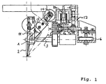
- Fig. 1 shows a bonding head for thin or thick wire according to a first embodiment, where the numeral 12 indicates a frame to which the components are attached. As will be understood, the entire bonding head moves vertically within the bonding machine (not shown) to approach and retract from the substrate.
- the wedge 2 is provided for guiding a wire 1 to a point on the substrate where a bond is to be formed.
- the wire 1 is supplied by the wire supply means 13, which include a wire clamp 11. Operation of the wire supply means 13 will be discussed in more detail below.
- the wedge 2 is fixed to a transducer 3 which provides the necessary ultrasonic energy for bonding.
- the transducer 3 is fixed to a transducer holder 7, which is secured to the frame 12 by support means 8, 9.
- the support means include spring means 9a, 9b as well as a linear actuator 8 mounted to variably tension the spring means 9a, 9b.
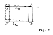
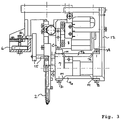
- the spring means preferably comprise at least two leaf springs 9a, 9b. As seen in the schematic diagram of Fig. 2, one end A, B of each leaf spring is fixed to the frame 12. As seen in the embodiment of Fig. 1, the springs 9a, 9b are fixed at their right hand end by bolts to the frame 12. In addition, the other end of the leaf springs are fixed to the transducer holder 7. The securement of the leaf springs 9a, 9b to the head frame 12 and the holder 7 are shown even more clearly in Fig. 3.
- the spring mounting of the transducer holder 7 may be accomplished in various configurations.
- two or four leaf springs are arranged substantially parallel to one another to form a parallelogram as shown in Fig. 2.
- four leaf springs are provided whereby only two springs 9a, 9b are visible in the side view. Two more leaf springs are present behind these two, all four of the springs being parallel and forming a parallelepided.
- the leaf springs 9a, 9b are deflected, whereby the parallel relationship between the springs is maintained.
- a stiffening member which in the figure is a rib disposed plane to the paper and perpendicular to the direction of deflection of the leaf springs.
- the linear actuator 8 comprises a fixed element 8b secured to the frame 12 and a cooperating element 8a secured to the transducer holder 7.
- the actuator 8 is preferably of the linear motor type by which the cooperating element 8a is moved linearly with respect to the fixed element 8b by means of application of a magnetic field.
- the cooperating element 8a undergoes linear displacement thereby causing deflection of the spring means 9a, 9b in the direction toward or away from the substrate, namely substantially in vertical direction.
- the force to be applied to the wire for bonding can be adjusted by adjusting the displacement of the leaf springs 9a, 9b by means of the linear actuator 8.
- the springs 9a, 9b Prior to contact of the wire with the substrate, the springs 9a, 9b are deflected against the return force of the springs as shown in Fig. 2.
- the rest position of the springs is illustrated by the solid line, whereas the deflected position is indicated by dashed lines.
- a return force arises towards the rest position, the magnitude of the force depending on the magnitude of deflection.
- this force is transmitted through the transducer holder, the transducer and finally to the wire providing the bonding force.
- the magnitude of the bonding force can be preset to a desired value and adjusted by the amount of movement of the linear actuator when tensioning the springs.
- detecting means 6 are also provided, preferably in the form of a piezo detector.
- the transducer holder 7 is shown in cross-section in Fig. 1 and has an extension piece shown at the right of the figure above the piezo element 6.
- the extension piece engages the piezo element 6, whereby the biasing force of the springs can be measured.
- the output of the piezo detector 6 is connected to control means (not shown) for automatically adjusting the biasing force, which is directly related to the bonding force applied by the wedge.
- the control means include an electric control loop connected to the drive mechanism of the linear actuator 8. The control means measure the present bonding force and compare this with a prestored desired force. If the deviation is larger than an acceptable amount, the linear actuator is activated to provide the proper displacement of the springs whereby the desired bonding force is achieved.
- the bonding head of Fig. 3 is suitable for thick wire and gold wire.
- the piezo element 6 is located on the other side of the wedge 2.
- the transducer holder 7 is provided with a linkage 15, which contacts a mechanical coupler 16.
- the coupler 16 engages the piezo element 6.
- the bonding head is provided with a wire supply means 13 which is mounted on a linearly movable guide with an excenter drive 14.
- the motion of said drive 14 is controlled by a stepping motor.
- the supply means 13 advances the wire 1 to the wedge 2.
- the wire 1 is clamped by the clamping means 11.
- the supply means 13 can be pivoted about the axis 14, whereby the clamping means 11 are also pivoted. In this manner, the wire 1 can be supplied to the wedge 2 at various different angles with respect to the vertical direction of the wedge, as indicated by the dash-dot lines in Fig. 1.
- the supply means are adjustable such that delivery angles of 30°, 45° and 60° are possible.
Landscapes
- Engineering & Computer Science (AREA)
- Mechanical Engineering (AREA)
- Wire Bonding (AREA)
Priority Applications (4)
| Application Number | Priority Date | Filing Date | Title |
|---|---|---|---|
| AT97104313T ATE204219T1 (de) | 1997-03-13 | 1997-03-13 | Bondkopf |
| DE69706134T DE69706134T2 (de) | 1997-03-13 | 1997-03-13 | Bondkopf |
| EP97104313A EP0864392B1 (de) | 1997-03-13 | 1997-03-13 | Bondkopf |
| US08/826,351 US5950903A (en) | 1997-03-13 | 1997-03-25 | Bonding head |
Applications Claiming Priority (2)
| Application Number | Priority Date | Filing Date | Title |
|---|---|---|---|
| EP97104313A EP0864392B1 (de) | 1997-03-13 | 1997-03-13 | Bondkopf |
| US08/826,351 US5950903A (en) | 1997-03-13 | 1997-03-25 | Bonding head |
Publications (2)
| Publication Number | Publication Date |
|---|---|
| EP0864392A1 true EP0864392A1 (de) | 1998-09-16 |
| EP0864392B1 EP0864392B1 (de) | 2001-08-16 |
Family
ID=26145313
Family Applications (1)
| Application Number | Title | Priority Date | Filing Date |
|---|---|---|---|
| EP97104313A Expired - Lifetime EP0864392B1 (de) | 1997-03-13 | 1997-03-13 | Bondkopf |
Country Status (2)
| Country | Link |
|---|---|
| US (1) | US5950903A (de) |
| EP (1) | EP0864392B1 (de) |
Cited By (3)
| Publication number | Priority date | Publication date | Assignee | Title |
|---|---|---|---|---|
| EP0942258A3 (de) * | 1998-03-13 | 2000-05-17 | Mitutoyo Corporation | Konstant-Druck-Mechanismus und Konstant-Moment-Mechanismus für eine Messprobe |
| WO2000067944A1 (de) * | 1999-05-07 | 2000-11-16 | Hesse & Knipps Gmbh | Ultraschall-drahtbondeinrichtung |
| WO2011023159A1 (de) * | 2009-08-26 | 2011-03-03 | Melzer Maschinenbau Gmbh | Verfahren und vorrichtung zur herstellung einer transpondereinheit |
Families Citing this family (10)
| Publication number | Priority date | Publication date | Assignee | Title |
|---|---|---|---|---|
| DE59701709C5 (de) * | 1996-02-12 | 2014-01-09 | Smartrac Ip B.V. | Verfahren und vorrichtung zur kontaktierung eines drahtleiters |
| US6206275B1 (en) | 1999-10-13 | 2001-03-27 | F & K Delvotec Bondtechnik Gmbh | Deep access, close proximity, fine pitch bonding of large wire |
| US6513696B1 (en) * | 2000-08-28 | 2003-02-04 | Asm Assembly Automation Ltd. | Wedge bonding head |
| US6616031B2 (en) | 2001-07-17 | 2003-09-09 | Asm Assembly Automation Limited | Apparatus and method for bond force control |
| CN101712097B (zh) * | 2008-11-24 | 2011-09-07 | 深圳市创唯星自动化设备有限公司 | 带静电吸附的劈刀结构、超声波焊接设备及键合方法 |
| CN105552002A (zh) * | 2015-12-18 | 2016-05-04 | 中国电子科技集团公司第二研究所 | 一种引线楔焊微小力输出机构 |
| CN105598613A (zh) * | 2015-12-18 | 2016-05-25 | 中国电子科技集团公司第二研究所 | 全自动引线键合机焊头 |
| CN105590874A (zh) * | 2015-12-18 | 2016-05-18 | 中国电子科技集团公司第二研究所 | 一种引线楔焊微小力输出机构的工作方法 |
| CN106641146A (zh) * | 2016-09-22 | 2017-05-10 | 宁波尚进自动化科技有限公司 | 一种连杆机构 |
| CN115533269B (zh) * | 2022-12-05 | 2023-03-21 | 宁波尚进自动化科技有限公司 | 45度全自动楔焊键合头装置 |
Citations (4)
| Publication number | Priority date | Publication date | Assignee | Title |
|---|---|---|---|---|
| US4598853A (en) * | 1984-05-21 | 1986-07-08 | Hughes Aircraft Company | Open-center flexural pivot wire bonding head |
| EP0203597A2 (de) * | 1985-05-31 | 1986-12-03 | Emhart Industries, Inc. | Verbindungskopf |
| US4976392A (en) | 1989-08-11 | 1990-12-11 | Orthodyne Electronics Corporation | Ultrasonic wire bonder wire formation and cutter system |
| EP0540189A2 (de) * | 1991-10-30 | 1993-05-05 | F & K Delvotec Bondtechnik GmbH | Steuerungssystem |
Family Cites Families (4)
| Publication number | Priority date | Publication date | Assignee | Title |
|---|---|---|---|---|
| JPS59130433A (ja) * | 1983-01-17 | 1984-07-27 | Toshiba Corp | ワイヤボンディング装置 |
| JPS62150838A (ja) * | 1985-12-25 | 1987-07-04 | Hitachi Ltd | 検出方法および装置 |
| US5277355A (en) * | 1992-11-25 | 1994-01-11 | Kulicke And Soffa Investments, Inc. | Self-aligning fine wire clamp |
| US5452838A (en) * | 1993-07-13 | 1995-09-26 | F & K Delvotec Bondtechnik Gmbh | Bonding head for an ultrasonic bonding machine |
-
1997
- 1997-03-13 EP EP97104313A patent/EP0864392B1/de not_active Expired - Lifetime
- 1997-03-25 US US08/826,351 patent/US5950903A/en not_active Expired - Lifetime
Patent Citations (5)
| Publication number | Priority date | Publication date | Assignee | Title |
|---|---|---|---|---|
| US4598853A (en) * | 1984-05-21 | 1986-07-08 | Hughes Aircraft Company | Open-center flexural pivot wire bonding head |
| EP0203597A2 (de) * | 1985-05-31 | 1986-12-03 | Emhart Industries, Inc. | Verbindungskopf |
| US4976392A (en) | 1989-08-11 | 1990-12-11 | Orthodyne Electronics Corporation | Ultrasonic wire bonder wire formation and cutter system |
| DE4016720A1 (de) | 1989-08-11 | 1991-02-14 | Orthodyne Electronics Corp | Verfahren und vorrichtung zum ultraschallbonden |
| EP0540189A2 (de) * | 1991-10-30 | 1993-05-05 | F & K Delvotec Bondtechnik GmbH | Steuerungssystem |
Cited By (4)
| Publication number | Priority date | Publication date | Assignee | Title |
|---|---|---|---|---|
| EP0942258A3 (de) * | 1998-03-13 | 2000-05-17 | Mitutoyo Corporation | Konstant-Druck-Mechanismus und Konstant-Moment-Mechanismus für eine Messprobe |
| US6128968A (en) * | 1998-03-13 | 2000-10-10 | Mitutuyo Corporation | Constant-pressure mechanism and constant-torque mechanism |
| WO2000067944A1 (de) * | 1999-05-07 | 2000-11-16 | Hesse & Knipps Gmbh | Ultraschall-drahtbondeinrichtung |
| WO2011023159A1 (de) * | 2009-08-26 | 2011-03-03 | Melzer Maschinenbau Gmbh | Verfahren und vorrichtung zur herstellung einer transpondereinheit |
Also Published As
| Publication number | Publication date |
|---|---|
| US5950903A (en) | 1999-09-14 |
| EP0864392B1 (de) | 2001-08-16 |
Similar Documents
| Publication | Publication Date | Title |
|---|---|---|
| EP0864392B1 (de) | Bondkopf | |
| JP2682861B2 (ja) | 工作物の寸法をチェックする装置 | |
| KR100269964B1 (ko) | 워크피스 위치 결정방법 및 그 장치 | |
| US6698159B2 (en) | Adjustable shuttle stop apparatus | |
| EP0203597B1 (de) | Verbindungskopf | |
| JP3992853B2 (ja) | 表面追従型測定機 | |
| US5901896A (en) | Balanced low mass miniature wire clamp | |
| JP3646889B2 (ja) | シート材切断機の刃物用パイロット装置 | |
| US10900765B2 (en) | Form measuring apparatus | |
| US4598853A (en) | Open-center flexural pivot wire bonding head | |
| US5360276A (en) | Printing device with adjustable printing head gap | |
| US6513696B1 (en) | Wedge bonding head | |
| US5979737A (en) | Ultrasonic bonding head comprising a linear motor for adjusting the pressure according to a piezo detector | |
| CN101720266B (zh) | 手持式工具机 | |
| US20080302857A1 (en) | Wire clamp for a wire bonder | |
| JPH08506758A (ja) | 調整可能なブレードを備えたコーティング装置 | |
| US7549569B2 (en) | Wire clamp gap control mechanism and method | |
| US3601304A (en) | Wire bonder | |
| US4614038A (en) | Head for measuring diameters of cylindrical parts | |
| JP2002517910A (ja) | 部品を動かす送りユニット | |
| EP0445296A1 (de) | Einrichtung zum regeln der spannung eines fadens | |
| DE69706134T2 (de) | Bondkopf | |
| CN1290774A (zh) | 具有花压板的经编机 | |
| EP2067728A1 (de) | Garnspannungssensor für Garnzuführgeräte | |
| CN222683908U (zh) | 一种改进型机械手排线装置的传感控制装置 |
Legal Events
| Date | Code | Title | Description |
|---|---|---|---|
| PUAI | Public reference made under article 153(3) epc to a published international application that has entered the european phase |
Free format text: ORIGINAL CODE: 0009012 |
|
| AK | Designated contracting states |
Kind code of ref document: A1 Designated state(s): AT CH DE FR GB IT LI NL |
|
| 17P | Request for examination filed |
Effective date: 19981023 |
|
| AKX | Designation fees paid |
Free format text: AT CH DE FR GB IT LI NL |
|
| RBV | Designated contracting states (corrected) |
Designated state(s): AT CH DE FR GB IT LI NL |
|
| TPAD | Observations filed by third parties |
Free format text: ORIGINAL CODE: EPIDOS TIPA |
|
| GRAG | Despatch of communication of intention to grant |
Free format text: ORIGINAL CODE: EPIDOS AGRA |
|
| GRAG | Despatch of communication of intention to grant |
Free format text: ORIGINAL CODE: EPIDOS AGRA |
|
| GRAH | Despatch of communication of intention to grant a patent |
Free format text: ORIGINAL CODE: EPIDOS IGRA |
|
| 17Q | First examination report despatched |
Effective date: 20010125 |
|
| GRAH | Despatch of communication of intention to grant a patent |
Free format text: ORIGINAL CODE: EPIDOS IGRA |
|
| GRAA | (expected) grant |
Free format text: ORIGINAL CODE: 0009210 |
|
| AK | Designated contracting states |
Kind code of ref document: B1 Designated state(s): AT CH DE FR GB IT LI NL |
|
| REF | Corresponds to: |
Ref document number: 204219 Country of ref document: AT Date of ref document: 20010915 Kind code of ref document: T |
|
| REG | Reference to a national code |
Ref country code: CH Ref legal event code: NV Representative=s name: TROESCH SCHEIDEGGER WERNER AG Ref country code: CH Ref legal event code: EP |
|
| REF | Corresponds to: |
Ref document number: 69706134 Country of ref document: DE Date of ref document: 20010920 |
|
| ET | Fr: translation filed | ||
| REG | Reference to a national code |
Ref country code: GB Ref legal event code: IF02 |
|
| PLBQ | Unpublished change to opponent data |
Free format text: ORIGINAL CODE: EPIDOS OPPO |
|
| PLBI | Opposition filed |
Free format text: ORIGINAL CODE: 0009260 |
|
| PLBF | Reply of patent proprietor to notice(s) of opposition |
Free format text: ORIGINAL CODE: EPIDOS OBSO |
|
| 26 | Opposition filed |
Opponent name: HESSE & KNIPPS GMBH Effective date: 20020516 |
|
| NLR1 | Nl: opposition has been filed with the epo |
Opponent name: HESSE & KNIPPS GMBH |
|
| PLBF | Reply of patent proprietor to notice(s) of opposition |
Free format text: ORIGINAL CODE: EPIDOS OBSO |
|
| PLBO | Opposition rejected |
Free format text: ORIGINAL CODE: EPIDOS REJO |
|
| PLBN | Opposition rejected |
Free format text: ORIGINAL CODE: 0009273 |
|
| STAA | Information on the status of an ep patent application or granted ep patent |
Free format text: STATUS: OPPOSITION REJECTED |
|
| 27O | Opposition rejected |
Effective date: 20030610 |
|
| NLR2 | Nl: decision of opposition |
Effective date: 20030610 |
|
| PGFP | Annual fee paid to national office [announced via postgrant information from national office to epo] |
Ref country code: GB Payment date: 20040225 Year of fee payment: 8 |
|
| PGFP | Annual fee paid to national office [announced via postgrant information from national office to epo] |
Ref country code: FR Payment date: 20040318 Year of fee payment: 8 |
|
| PGFP | Annual fee paid to national office [announced via postgrant information from national office to epo] |
Ref country code: AT Payment date: 20040322 Year of fee payment: 8 |
|
| PGFP | Annual fee paid to national office [announced via postgrant information from national office to epo] |
Ref country code: CH Payment date: 20040323 Year of fee payment: 8 |
|
| PG25 | Lapsed in a contracting state [announced via postgrant information from national office to epo] |
Ref country code: IT Free format text: LAPSE BECAUSE OF NON-PAYMENT OF DUE FEES;WARNING: LAPSES OF ITALIAN PATENTS WITH EFFECTIVE DATE BEFORE 2007 MAY HAVE OCCURRED AT ANY TIME BEFORE 2007. THE CORRECT EFFECTIVE DATE MAY BE DIFFERENT FROM THE ONE RECORDED. Effective date: 20050313 Ref country code: GB Free format text: LAPSE BECAUSE OF NON-PAYMENT OF DUE FEES Effective date: 20050313 Ref country code: AT Free format text: LAPSE BECAUSE OF NON-PAYMENT OF DUE FEES Effective date: 20050313 |
|
| PG25 | Lapsed in a contracting state [announced via postgrant information from national office to epo] |
Ref country code: LI Free format text: LAPSE BECAUSE OF NON-PAYMENT OF DUE FEES Effective date: 20050331 Ref country code: CH Free format text: LAPSE BECAUSE OF NON-PAYMENT OF DUE FEES Effective date: 20050331 |
|
| REG | Reference to a national code |
Ref country code: CH Ref legal event code: PL |
|
| GBPC | Gb: european patent ceased through non-payment of renewal fee |
Effective date: 20050313 |
|
| PG25 | Lapsed in a contracting state [announced via postgrant information from national office to epo] |
Ref country code: FR Free format text: LAPSE BECAUSE OF NON-PAYMENT OF DUE FEES Effective date: 20051130 |
|
| REG | Reference to a national code |
Ref country code: FR Ref legal event code: ST Effective date: 20051130 |
|
| PGFP | Annual fee paid to national office [announced via postgrant information from national office to epo] |
Ref country code: NL Payment date: 20070829 Year of fee payment: 11 |
|
| PG25 | Lapsed in a contracting state [announced via postgrant information from national office to epo] |
Ref country code: NL Free format text: LAPSE BECAUSE OF NON-PAYMENT OF DUE FEES Effective date: 20081001 |
|
| NLV4 | Nl: lapsed or anulled due to non-payment of the annual fee |
Effective date: 20081001 |
|
| PGFP | Annual fee paid to national office [announced via postgrant information from national office to epo] |
Ref country code: DE Payment date: 20160330 Year of fee payment: 20 |
|
| REG | Reference to a national code |
Ref country code: DE Ref legal event code: R071 Ref document number: 69706134 Country of ref document: DE |