EP0864407B1 - Vorrichtung zum Vergüten von Kantenflächen an Werkstücken aus Spanplattenmaterial - Google Patents
Vorrichtung zum Vergüten von Kantenflächen an Werkstücken aus Spanplattenmaterial Download PDFInfo
- Publication number
- EP0864407B1 EP0864407B1 EP98102157A EP98102157A EP0864407B1 EP 0864407 B1 EP0864407 B1 EP 0864407B1 EP 98102157 A EP98102157 A EP 98102157A EP 98102157 A EP98102157 A EP 98102157A EP 0864407 B1 EP0864407 B1 EP 0864407B1
- Authority
- EP
- European Patent Office
- Prior art keywords
- groove
- slide block
- workpiece
- filler compound
- inlet
- Prior art date
- Legal status (The legal status is an assumption and is not a legal conclusion. Google has not performed a legal analysis and makes no representation as to the accuracy of the status listed.)
- Expired - Lifetime
Links
- 238000007789 sealing Methods 0.000 title description 2
- 229920002522 Wood fibre Polymers 0.000 title 1
- 150000001875 compounds Chemical class 0.000 claims description 18
- 239000000463 material Substances 0.000 claims description 12
- 239000011093 chipboard Substances 0.000 claims description 8
- 238000010438 heat treatment Methods 0.000 claims description 2
- 239000000945 filler Substances 0.000 claims 6
- 239000012530 fluid Substances 0.000 claims 1
- 230000008018 melting Effects 0.000 claims 1
- 238000002844 melting Methods 0.000 claims 1
- 239000000126 substance Substances 0.000 claims 1
- 239000011248 coating agent Substances 0.000 description 5
- 238000000576 coating method Methods 0.000 description 5
- 239000002245 particle Substances 0.000 description 5
- 239000011148 porous material Substances 0.000 description 3
- 239000007788 liquid Substances 0.000 description 2
- 238000000034 method Methods 0.000 description 2
- 238000010422 painting Methods 0.000 description 2
- 235000011837 pasties Nutrition 0.000 description 2
- 239000003566 sealing material Substances 0.000 description 2
- 230000015572 biosynthetic process Effects 0.000 description 1
- 230000000295 complement effect Effects 0.000 description 1
- 230000006835 compression Effects 0.000 description 1
- 238000007906 compression Methods 0.000 description 1
- 238000001816 cooling Methods 0.000 description 1
- 239000011888 foil Substances 0.000 description 1
- 238000004519 manufacturing process Methods 0.000 description 1
- 238000003801 milling Methods 0.000 description 1
- 239000000203 mixture Substances 0.000 description 1
- 230000035515 penetration Effects 0.000 description 1
- 238000012805 post-processing Methods 0.000 description 1
- 238000003825 pressing Methods 0.000 description 1
- 230000000630 rising effect Effects 0.000 description 1
- 238000007711 solidification Methods 0.000 description 1
- 230000008023 solidification Effects 0.000 description 1
- 239000000725 suspension Substances 0.000 description 1
- 229920001169 thermoplastic Polymers 0.000 description 1
- 239000002966 varnish Substances 0.000 description 1
- 239000002023 wood Substances 0.000 description 1
Images


Classifications
-
- B—PERFORMING OPERATIONS; TRANSPORTING
- B27—WORKING OR PRESERVING WOOD OR SIMILAR MATERIAL; NAILING OR STAPLING MACHINES IN GENERAL
- B27N—MANUFACTURE BY DRY PROCESSES OF ARTICLES, WITH OR WITHOUT ORGANIC BINDING AGENTS, MADE FROM PARTICLES OR FIBRES CONSISTING OF WOOD OR OTHER LIGNOCELLULOSIC OR LIKE ORGANIC MATERIAL
- B27N7/00—After-treatment, e.g. reducing swelling or shrinkage, surfacing; Protecting the edges of boards against access of humidity
Definitions
- the invention relates to a device for painting a liquid or pasty leveling compound in the open, pore-like cavities on the cut Edge surfaces of workpieces made of chip material according to the Generic features of claim 1.
- Particle boards are made from a bed made using the air classifier method is formed, pressed, the fine wood particles on both sides of the outer surfaces of the chipboard find the larger ones towards the center of the chipboard Chips are arranged.
- a surface coating also on the narrow surface sides are applied, through which the coarser Structure of the chipboard material not towards the middle should be visible.
- pore-like cavities that the cut edges give a rugged appearance.
- Chipboard material is a leveling or remuneration compound with which the open pores on the edge surfaces of the workpieces are closed so that there is a forms a smooth surface on which a coating material like a foil, a veneer or a varnish, so applied can be that in retrospect the coarse chip structure is no longer recognizable.
- the leveling compounds have a liquid or pasty consistency and they harden after application out.
- the painting is carried out by means of a Squeegee, a roller or a spatula on which the workpieces are passed in one pass.
- the document US 5 085 891 A describes a Sealing device for post-treatment of edges on workpieces that consist of a material composition.
- the known device has a body like a Sliding block with a groove on the edge contour of the is adapted to the respective workpiece. In the area of this groove there is an inlet nozzle through which an edge sealing material like a melted thermoplastic Plastic that is pushed in. Due to a generated Relative movement between the workpiece and the above Device is along the entire edge of the workpiece applied a coating.
- a similar device also describes document AU 549 776 B, also here is a sealing material on the edge profile of a Plate applied, which consists of a particle material.
- the invention is based on the object of a device of the type mentioned at the beginning, with the one more precise application of the leveling compound under deeper Penetration into the cut edge surfaces of the workpieces due to a high pressure in the elongated Hollow or groove of the sliding block is possible.
- This object is achieved according to the invention in such Device by the characterizing features of the claim 1 solved.
- the to be treated Workpiece edge surfaces over a longer distance in Be brought into contact with the balancing mass whereby through appropriate cross-sectional and surface design the elongated hollow or groove in the sliding block influences one smooth formation of the surface of the hardened leveling compound can be taken.
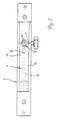
- the workpiece 1 shows a workpiece 1 in which it is is a strip made of a chipboard material has been cut. As particularly illustrated in FIG. 3, the workpiece 1 has a milling rounded edge surface 2, on the corresponding to the Chipboard base material, especially in the middle area There are open pores between coarse chip particles that must be closed for a subsequent coating. For this purpose, the edge surface 2 of the workpiece 1 applied a leveling compound and brushed it into the pores, what happens in the run. To do this, the workpiece 1 pressed against a conveyor 3, the a plurality or a plurality of feed rollers 4, which complement each other to form a straight conveyor line.
- a sliding block 5 is arranged opposite the conveying device 3, between that and the conveyor 3 that Workpiece 1 is passed, the sliding block also pressing the workpiece 1 onto the conveyor device 3 can get.
- the sliding block has facing the workpiece 1 Long side a cavity or groove 6, the basic cross-sectional shape Figure 3 can be seen.
- the workpiece 1 dips with its edge surface 2 to be treated in this groove 6 a, which is why an adjustment of the cross-sectional shape of the groove 6 to the respective cross-sectional shape of the workpiece edge surface 2 is required.
- an appropriately adapted sliding block 5 can be used.
- the balancing mass is in the groove 6 of the sliding block 5 indented, this happens via a channel 7 from which two channel-shaped inlets 8 are branched out as is Figures 2 and 3 results.
- the groove 6 has its largest cross section, here is an enlarged groove space 9 is formed to at this point to have a larger amount of the balancing mass available. From this enlarged groove space 9 takes in Direction of arrow A passing workpiece 1 on it Edge surface 2 with the leveling compound that to the end of the outlet on the sliding block 5 is pressed more and more because the cross section of the groove 6 tapers towards the outlet end.
- the sliding block 5 is groping against the respective workpiece 1 pressed, which means that he has any tolerances follows the workpiece edge and no constraints between the Sliding block 5 and the respective workpiece 1 can exist. So that a bump on the inlet side of the sliding block 5 is prevented, the groove 6 expands here by one Form slope 14.
- a leveling compound is used, which by Heat can be liquefied, i.e. it can be melted. So that none too rapid cooling and solidification of the balancing mass, pulled along in the slot 6 in the groove 6 is, a heating rod 15 is in the sliding block 5 arranged, which is substantially parallel to the groove 6.
- the sliding block 5 is arranged on a support 16, which in Direction to the conveyor 3 is deliverable, wherein the support 16 is adjustable in a total of three axes.
- the elastic contact of the sliding block 5 on the edge surface 2 of the workpiece 1 is by a compression spring device 17, 18 causes that from a pneumatic cylinder and from separable Push rods 17 so that the sliding block 5th can be replaced at Support 16.
- the travel of the The sliding block 5 opposite the support 6 is on the one hand
- Bolt 19 limits which these two parts together connect with the sliding 5 on the shaft the bolt 19 is axially displaceable.
- the end position the sliding 5 is by a stop forming nuts 20 specified, which is adjusted to adjust the sliding block 5 can be.
- a corresponding continuous machine or device can have several such carrier systems in succession, such as it is shown in principle in Figure 1.
Landscapes
- Life Sciences & Earth Sciences (AREA)
- Engineering & Computer Science (AREA)
- Manufacturing & Machinery (AREA)
- Wood Science & Technology (AREA)
- Forests & Forestry (AREA)
- Coating Apparatus (AREA)
Description
- Fig. 1
- die Draufsicht auf eine Einstreichvorrichtung mit einem Gleitstein,
- Fig. 2
- die Seitansicht des in Figur 1 dargestellten Gleitsteins und
- Fig. 3
- eine Querschnittsdarstellung des Gleitsteins gemäß den Figuren 1 und 2.
Claims (10)
- Vorrichtung zum Einstreichen einer flüssigen oder pastösen Ausgleichsmasse in die offenen, porenartigen Hohlräume an den angeschnittenen Kantenflächen von Werkstükken aus Spanplattenmaterial, mittels zumindest eines Gleitsteins (5) mit einer länglichen Hohle oder Nut (6), deren Querschnitt an ein Umgreifen der daran eng entlangzuführenden Werkstück-Kantenflächen (2) angepaßt ist und in deren Bereich ein Einlaß (8) für die Ausgleichsmasse angeordnet ist,
dadurch gekennzeichnet, daß die Querschnittsgestalt der Nut (6) des Gleitsteins (5) derart an die Umhüllungskontur der jeweiligen Werkstück-Kantenflächen (2) angepaßt ist, daß die die Kantenflächen (2) beidseits begrenzenden, miteinander parallelen Kanten (12) des Werkstücks (1) an den Nutflanken (13) dichtend anliegen und zwischen der jeweiligen Kantenfläche (2) und dem Nutgrund (10) ein Spalt (11) zur Mitnahme der Ausgleichsmasse vom Einlaß (8) weg besteht und daß ferner die Tiefe der Nut (6) vom Einlaß (8) für die Ausgleichsmasse zum Auslaufende für die Werkstück-Kantenfläche (2) hin und entsprechend der Querschnitt des Mitnahmespaltes (11) sich verringert. - Vorrichtung nach Anspruch 1,
dadurch gekennzeichnet, daß der Einlaß (8) für die Ausgleichsmasse in einen gegenüber dem benachbarten Nutquerschnitt vergrößerten Nutraum (9) mündet. - Vorrichtung nach einem der Ansprüche 1 oder 2,
dadurch gekennzeichnet, daß die Ausgleichsmasse eine wärmeschmelzbare Substanz und entsprechend der Gleitstein (5) beheizbar ist. - Vorrichtung nach Anspruch 3,
dadurch gekennzeichnet, daß in dem Gleitstein (5) parallel oder etwa parallel zur Nut (6) zumindest ein Heizstab (15) angeordnet ist. - Vorrichtung nach einem der Ansprüche 1 bis 4,
dadurch gekennzeichnet, daß die Nut (6) an der Einlaufseite für die Werkstück-Kantenfläche (2) unter Bildung einer Auflaufschrägen (14) erweitert ist. - Vorrichtung nach einem der Ansprüche 1 bis 5,
dadurch gekennzeichnet, daß der Gleitstein (5) an einem relativ zu einer Werkstücktransport- und -führungsvorrichtung (3) in drei Achsen zustellbaren Support (16) angeordnet ist. - Vorrichtung nach Anspruch 6,
dadurch gekennzeichnet, daß der Gleitstein (5) an den durchlaufenden Werkstück-Kantenflächen (2) tastend abgestützt ist. - Vorrichtung nach Anspruch 7,
dadurch gekennzeichnet, daß zwischen dem Support (16) und dem Gleitstein (5) eine Druckfedervorrichtung (17, 18) angeordnet ist. - Vorrichtung nach Anspruch 8,
dadurch gekennzeichnet, daß am Support (16) den elastischen Hub des Gleitsteins (5) begrenzende, verstellbare Anschläge (20, 21) angeordnet sind. - Vorrichtung nach einem der Ansprüche 6 bis 9,
dadurch gekennzeichnet, daß der Gleitstein (5) am Support (16) auswechselbar angeordnet ist.
Applications Claiming Priority (2)
| Application Number | Priority Date | Filing Date | Title |
|---|---|---|---|
| DE19709864A DE19709864C2 (de) | 1997-03-11 | 1997-03-11 | Vorrichtung zum Vergüten von Kantenflächen an Werkstücken aus Spanplattenmaterial |
| DE19709864 | 1997-03-11 |
Publications (2)
| Publication Number | Publication Date |
|---|---|
| EP0864407A1 EP0864407A1 (de) | 1998-09-16 |
| EP0864407B1 true EP0864407B1 (de) | 2002-06-05 |
Family
ID=7822891
Family Applications (1)
| Application Number | Title | Priority Date | Filing Date |
|---|---|---|---|
| EP98102157A Expired - Lifetime EP0864407B1 (de) | 1997-03-11 | 1998-02-07 | Vorrichtung zum Vergüten von Kantenflächen an Werkstücken aus Spanplattenmaterial |
Country Status (2)
| Country | Link |
|---|---|
| EP (1) | EP0864407B1 (de) |
| DE (2) | DE19709864C2 (de) |
Families Citing this family (7)
| Publication number | Priority date | Publication date | Assignee | Title |
|---|---|---|---|---|
| DE10317953B3 (de) * | 2003-04-17 | 2005-02-03 | Homag Holzbearbeitungssysteme Ag | Vorrichtung und Verfahren zur Durchlaufbearbeitung von Werkstücken im Kantenbereich |
| CN104354217B (zh) * | 2014-10-11 | 2016-04-06 | 东莞市南兴家具装备制造股份有限公司 | 封边机的封边带前后平切装置 |
| CN105016106A (zh) * | 2015-07-23 | 2015-11-04 | 浙江采丰木业有限公司 | 一种门板封边的封边条输送装置 |
| CN105563608B (zh) * | 2016-02-25 | 2018-01-16 | 南兴装备股份有限公司 | 封边带刻槽涂胶压带机构 |
| CN105946089B (zh) * | 2016-06-30 | 2018-08-21 | 哈尔滨天成顺杰实业有限公司 | 一种用于秸秆板生产系统的封端总成 |
| CN110587774B (zh) * | 2019-10-28 | 2021-05-07 | 东莞欧德雅装饰材料有限公司 | 一种利用封边条对板材封边的设备 |
| DE102021132156B3 (de) | 2021-12-07 | 2023-04-27 | Konrad Scholz | Glättvorrichtung |
Family Cites Families (8)
| Publication number | Priority date | Publication date | Assignee | Title |
|---|---|---|---|---|
| US3967581A (en) * | 1971-07-06 | 1976-07-06 | Irvin Edward Zirbel | Apparatus for applying a coating to a workpiece edge |
| US4197078A (en) * | 1977-11-03 | 1980-04-08 | Masonite Corporation | Apparatus for edge treatment for fibreboard panels and the like |
| US4258651A (en) * | 1979-09-20 | 1981-03-31 | Knudtson Brice N | Apparatus for applying sealant to the irregular side edges of a panel |
| AU549776B2 (en) * | 1982-07-12 | 1986-02-13 | Csr Limited | Wax edge sealing |
| DD287606A7 (de) * | 1988-06-20 | 1991-03-07 | Wtz D. Holzverarbeitenden Industrie,De | Vorrichtung zum beschichten profilierter schmalflaechen von holzwerkstoffen |
| US5085891A (en) * | 1990-07-16 | 1992-02-04 | Nordson Corporation | Edge sealing apparatus and method |
| NL9102001A (nl) * | 1991-11-29 | 1993-06-16 | Houthandel Lambert Van Den Bos | Voorbehandeling van vezelplaten. |
| DE19518925A1 (de) * | 1995-05-23 | 1996-11-28 | Homag Maschinenbau Ag | Verfahren und Vorrichtung zur Durchlauf-Bearbeitung von im wesentlichen flächigen oder leistenförmigen Werkstücken aus offenporigen Holzwerkstoffen und dergleichen im Kantenbereich |
-
1997
- 1997-03-11 DE DE19709864A patent/DE19709864C2/de not_active Expired - Fee Related
-
1998
- 1998-02-07 EP EP98102157A patent/EP0864407B1/de not_active Expired - Lifetime
- 1998-02-07 DE DE59804273T patent/DE59804273D1/de not_active Expired - Fee Related
Also Published As
| Publication number | Publication date |
|---|---|
| EP0864407A1 (de) | 1998-09-16 |
| DE19709864C2 (de) | 2000-05-11 |
| DE19709864A1 (de) | 1998-09-17 |
| DE59804273D1 (de) | 2002-07-11 |
Similar Documents
| Publication | Publication Date | Title |
|---|---|---|
| DE1750580C3 (de) | Vorrichtung zum Aufbringen einer Thermoplast-Sperrschicht auf Teile der Gewinde von Kopfschrauben | |
| EP0499704B1 (de) | Vorrichtung zum Befetten von Werkstücken in Band- oder Platinenform | |
| DE69905864T2 (de) | Verfahren und system zum auftragen von lack | |
| DE2728741C2 (de) | ||
| DE3931793A1 (de) | Ein geraet zur beschichtung einer fahrenden bahn | |
| EP0455142A2 (de) | Profilschleifmaschine | |
| EP0864407B1 (de) | Vorrichtung zum Vergüten von Kantenflächen an Werkstücken aus Spanplattenmaterial | |
| DE19935117B4 (de) | Vorrichtung zum Aufbringen von formatmäßigen Klebstoffaufträgen auf eine Übertragungswalze | |
| DE10124695C2 (de) | Kantenanleimaggregat mit Andruckrolle | |
| AT409859B (de) | Vorrichtung zum füllen der randfugen von isolierglasscheiben mit einer dichtmasse | |
| DE3912742A1 (de) | Verfahren und vorrichtung zum beschichten profilierter schmalflaechen von holzwerkstoffen | |
| DE102006012373B3 (de) | Breitschlitzdüse und Verfahren zum Auftragen von hochviskosem Material | |
| DE69835772T2 (de) | Gerät zum ausbreiten und verteilen von teilchen auf einem materialband | |
| DE2731657C3 (de) | Verfahren zum kontinuierlichen Kaschieren von Werkstücken sowie Vorrichtung zur Durchführung dieses Verfahrens | |
| DE4326148B4 (de) | Einrichtung zur Streuung von Fasern, insbesondere von Spänen | |
| EP0999925B1 (de) | Verfahren und vorrichtung zum bearbeiten von im wesentlichen flächigen oder leistenförmigen werkstücken, insbesondere aus holzwerkstoffen | |
| DE2942748C2 (de) | Fördervorrichtung zum ein- oder mehrmaligen Durchstoßlackieren von einem Magazin entnehmbaren stab- oder hülsenförmigen Werkstücken | |
| DE19837036A1 (de) | Stegkantenaggregat | |
| DE1190368B (de) | Vorrichtung zum elektrostatischen Fluessigkeitsauftragen auf im wesentlichen ebene Werkstueckflaechen | |
| DE10317953B3 (de) | Vorrichtung und Verfahren zur Durchlaufbearbeitung von Werkstücken im Kantenbereich | |
| DE3104731C2 (de) | Verfahren und Vorrichtung zum kontinuierlichen Auf- bzw. Einbringen von Imprägnier- und/oder Lasierflüssigkeit auf Werkstücke | |
| DE69905654T2 (de) | Ausgabekopf zur Abgabe einer viskosen Flüssigkeit | |
| DE3134968A1 (de) | Vorrichtung zum innenseitigen auftragen einer schutzschicht auf die schweiss- bzw. loetnaht von dosenruempfen | |
| DE3115818C2 (de) | ||
| DE3114615A1 (de) | Schleifvorrichtung zur erzeugung konvexer prifle an geradlinigen kanten |
Legal Events
| Date | Code | Title | Description |
|---|---|---|---|
| PUAI | Public reference made under article 153(3) epc to a published international application that has entered the european phase |
Free format text: ORIGINAL CODE: 0009012 |
|
| AK | Designated contracting states |
Kind code of ref document: A1 Designated state(s): DE ES IT |
|
| AX | Request for extension of the european patent |
Free format text: AL;LT;LV;MK;RO;SI |
|
| 17P | Request for examination filed |
Effective date: 19980917 |
|
| AKX | Designation fees paid |
Free format text: DE ES IT |
|
| RBV | Designated contracting states (corrected) |
Designated state(s): DE ES IT |
|
| 17Q | First examination report despatched |
Effective date: 20010305 |
|
| GRAG | Despatch of communication of intention to grant |
Free format text: ORIGINAL CODE: EPIDOS AGRA |
|
| GRAG | Despatch of communication of intention to grant |
Free format text: ORIGINAL CODE: EPIDOS AGRA |
|
| GRAH | Despatch of communication of intention to grant a patent |
Free format text: ORIGINAL CODE: EPIDOS IGRA |
|
| GRAH | Despatch of communication of intention to grant a patent |
Free format text: ORIGINAL CODE: EPIDOS IGRA |
|
| GRAA | (expected) grant |
Free format text: ORIGINAL CODE: 0009210 |
|
| AK | Designated contracting states |
Kind code of ref document: B1 Designated state(s): DE ES IT |
|
| PG25 | Lapsed in a contracting state [announced via postgrant information from national office to epo] |
Ref country code: IT Free format text: LAPSE BECAUSE OF FAILURE TO SUBMIT A TRANSLATION OF THE DESCRIPTION OR TO PAY THE FEE WITHIN THE PRESCRIBED TIME-LIMIT;WARNING: LAPSES OF ITALIAN PATENTS WITH EFFECTIVE DATE BEFORE 2007 MAY HAVE OCCURRED AT ANY TIME BEFORE 2007. THE CORRECT EFFECTIVE DATE MAY BE DIFFERENT FROM THE ONE RECORDED. Effective date: 20020605 |
|
| REF | Corresponds to: |
Ref document number: 59804273 Country of ref document: DE Date of ref document: 20020711 |
|
| PG25 | Lapsed in a contracting state [announced via postgrant information from national office to epo] |
Ref country code: ES Free format text: LAPSE BECAUSE OF FAILURE TO SUBMIT A TRANSLATION OF THE DESCRIPTION OR TO PAY THE FEE WITHIN THE PRESCRIBED TIME-LIMIT Effective date: 20021220 |
|
| PLBE | No opposition filed within time limit |
Free format text: ORIGINAL CODE: 0009261 |
|
| STAA | Information on the status of an ep patent application or granted ep patent |
Free format text: STATUS: NO OPPOSITION FILED WITHIN TIME LIMIT |
|
| 26N | No opposition filed |
Effective date: 20030306 |
|
| PG25 | Lapsed in a contracting state [announced via postgrant information from national office to epo] |
Ref country code: DE Free format text: LAPSE BECAUSE OF NON-PAYMENT OF DUE FEES Effective date: 20030902 |