EP0864478B2 - Procédé pour commander des véhicules sur rails ainsi qu'ordinateur pour véhicule et système de commande de véhicule pour ce procédé - Google Patents
Procédé pour commander des véhicules sur rails ainsi qu'ordinateur pour véhicule et système de commande de véhicule pour ce procédé Download PDFInfo
- Publication number
- EP0864478B2 EP0864478B2 EP98440042A EP98440042A EP0864478B2 EP 0864478 B2 EP0864478 B2 EP 0864478B2 EP 98440042 A EP98440042 A EP 98440042A EP 98440042 A EP98440042 A EP 98440042A EP 0864478 B2 EP0864478 B2 EP 0864478B2
- Authority
- EP
- European Patent Office
- Prior art keywords
- vehicle
- computer
- route
- network
- location
- Prior art date
- Legal status (The legal status is an assumption and is not a legal conclusion. Google has not performed a legal analysis and makes no representation as to the accuracy of the status listed.)
- Expired - Lifetime
Links
- 238000000034 method Methods 0.000 title claims abstract description 23
- 238000005516 engineering process Methods 0.000 claims description 2
- 238000004458 analytical method Methods 0.000 claims 2
- 230000011664 signaling Effects 0.000 claims 1
- 239000004020 conductor Substances 0.000 description 6
- 230000005540 biological transmission Effects 0.000 description 5
- 238000007096 Glaser coupling reaction Methods 0.000 description 1
- 101100073352 Streptomyces halstedii sch1 gene Proteins 0.000 description 1
- 101100073357 Streptomyces halstedii sch2 gene Proteins 0.000 description 1
- 101100054666 Streptomyces halstedii sch3 gene Proteins 0.000 description 1
- 101100276531 Streptomyces halstedii sch4 gene Proteins 0.000 description 1
- 230000000712 assembly Effects 0.000 description 1
- 238000000429 assembly Methods 0.000 description 1
- 238000010276 construction Methods 0.000 description 1
- 230000000694 effects Effects 0.000 description 1
- 238000011156 evaluation Methods 0.000 description 1
- 230000008054 signal transmission Effects 0.000 description 1
- QERYCTSHXKAMIS-UHFFFAOYSA-M thiophene-2-carboxylate Chemical group [O-]C(=O)C1=CC=CS1 QERYCTSHXKAMIS-UHFFFAOYSA-M 0.000 description 1
Images


Classifications
-
- G—PHYSICS
- G05—CONTROLLING; REGULATING
- G05D—SYSTEMS FOR CONTROLLING OR REGULATING NON-ELECTRIC VARIABLES
- G05D1/00—Control of position, course, altitude or attitude of land, water, air or space vehicles, e.g. using automatic pilots
- G05D1/20—Control system inputs
- G05D1/24—Arrangements for determining position or orientation
- G05D1/247—Arrangements for determining position or orientation using signals provided by artificial sources external to the vehicle, e.g. navigation beacons
-
- B—PERFORMING OPERATIONS; TRANSPORTING
- B61—RAILWAYS
- B61L—GUIDING RAILWAY TRAFFIC; ENSURING THE SAFETY OF RAILWAY TRAFFIC
- B61L27/00—Central railway traffic control systems; Trackside control; Communication systems specially adapted therefor
- B61L27/04—Automatic systems, e.g. controlled by train; Change-over to manual control
-
- B—PERFORMING OPERATIONS; TRANSPORTING
- B61—RAILWAYS
- B61L—GUIDING RAILWAY TRAFFIC; ENSURING THE SAFETY OF RAILWAY TRAFFIC
- B61L27/00—Central railway traffic control systems; Trackside control; Communication systems specially adapted therefor
- B61L27/10—Operations, e.g. scheduling or time tables
- B61L27/16—Trackside optimisation of vehicle or train operation
-
- B—PERFORMING OPERATIONS; TRANSPORTING
- B61—RAILWAYS
- B61L—GUIDING RAILWAY TRAFFIC; ENSURING THE SAFETY OF RAILWAY TRAFFIC
- B61L3/00—Devices along the route for controlling devices on the vehicle or train, e.g. to release brake or to operate a warning signal
- B61L3/16—Continuous control along the route
- B61L3/22—Continuous control along the route using magnetic or electrostatic induction; using electromagnetic radiation
- B61L3/225—Continuous control along the route using magnetic or electrostatic induction; using electromagnetic radiation using separate conductors along the route
- B61L2003/226—German inductive continuous train control, called 'Linienzugbeeinflussung' [LZB]
-
- B—PERFORMING OPERATIONS; TRANSPORTING
- B61—RAILWAYS
- B61L—GUIDING RAILWAY TRAFFIC; ENSURING THE SAFETY OF RAILWAY TRAFFIC
- B61L2205/00—Communication or navigation systems for railway traffic
- B61L2205/04—Satellite based navigation systems, e.g. global positioning system [GPS]
-
- B—PERFORMING OPERATIONS; TRANSPORTING
- B61—RAILWAYS
- B61L—GUIDING RAILWAY TRAFFIC; ENSURING THE SAFETY OF RAILWAY TRAFFIC
- B61L2210/00—Vehicle systems
- B61L2210/02—Single autonomous vehicles
Definitions
- the invention relates to a method for controlling track-bound vehicles.
- the method can be used particularly advantageously for controlling automatic signal-guided traction vehicles (SST).
- SST automatic signal-guided traction vehicles
- the invention further relates to a vehicle computer and a vehicle control system, with which the process steps to be carried out on the vehicle side can be carried out.
- a Train Control System for Automatic Signaled Traction Vehicles is known from an article of B. Lege and G. Hillenbrand entitled “SST with EUROLOOP", Signal and Wire, April 1995, Vol. 4, pp. 123-127 ,
- Line conductor loops routed in the track center transmit data telegrams to an SST containing information about the term of the signal ahead.
- the signal term “SST stop” transmits the distance up to which the SST must have come to a standstill.
- the SST then brakes according to a braking curve calculated by a vehicle computer based on the distance transmitted, the current speed and the location.
- the SST travel the SST is informed of route information such as maximum speed, slow driving points or stopping points for the preceding route section in the form of data telegrams. This information is stored in an electronic memory and used to calculate the target speed.
- JP 8214415 discloses a system for autonomous driving position within a maneuvering area by a railway vehicle, which is equipped with a control device. Starting point and desired destination are entered to this controller. Each time before reaching a switch, this switch receives an actuating signal from the control device, which contains control information on the basis of the input starting point, destination and currently determined location. Thus, all points can be set from the starting point to the destination without the intervention of a central control device.
- the method described in the previous section is preferably used for automatically setting points in relatively narrowly defined areas in which a route can be more or less clearly determined from the starting point and destination.
- This method has the disadvantage that the entire route topology with all turnouts and points places in the vehicle or the control device must be known.
- the vehicle lacks any dynamic information, i. it has no information about the occupancy or trafficability of individual routes.
- the object of the invention is to provide a method for the secure control of track-bound vehicles, in particular those with an SST-like equipment.
- This method should in particular be particularly suitable for freight transport with small cargo units.
- the method is intended to allow a consignor of goods to deliver goods to an addressee in a simple and unbureaucratic manner by rail vehicles.
- the process should also allow effective and flexible use of the existing line capacity.
- the invention solves this problem by means of the features specified in claim 1.
- According to the input of the destination is done directly on. Rail vehicle.
- the forwarder thus needs to take no account of external conditions such as time of day, public holidays or the like. If the railway operator requires information on the type and quantity of cargo to be transported, the freight forwarder may enter this information using the keypad in addition to the destination.
- the destination is, together with the whereabouts and possibly the additional information entered, preferably transmitted via radio to a central dispatching computer.
- the whereabouts are determined by a locating device arranged in the vehicle and also communicated to the dispatching computer during the journey at each change of location.
- the disposition calculator responsible for a large area of the route network has all the vehicles in this area a suitable track to.
- the dispatcher is constantly informed of the whereabouts, the destinations and the priority of the drive of all the vehicles in its area. Therefore, for each vehicle, it can determine the optimum route for a given traffic situation and prioritize conflicts in the case of conflicts of higher priority.
- the scheduling computer can compile individual vehicles to larger train units and thus automate maneuvering operations due to the information converging in it.
- the invention provides that the dispatching computer notifies the trajectories to be set the interlockings, which then take over the route setting and - securing the route network.
- the interlockings have a direct effect on the affected line elements, ie on signals, switches, routed in the track conductor loops and facilities forcomparativelynzugbeein kgung.
- To control the vehicle is then - at least substantially - on existing line conductor systems, such as theizinzugbeein kgung (LZB), resorted.
- LZB the degree of existing line conductor systems
- the effort to be performed on the trackside is particularly small.
- Another advantageous embodiment according to claim 2 provides to control the vehicle in the manner known from the SST.
- the above-mentioned advantages of the SST are therefore also available for the solution according to the invention.
- the inventive method 100 for controlling track-bound vehicles in the form of a flow chart is shown.
- the start 101 of the method 100 may be, for example, that an operator on a rail-bound vehicle with the help of a key unlocks a vehicle computer.
- the vehicle computer which will be discussed in more detail below, is connected to input means by means of which the operator can enter the destination of the vehicle.
- the input means may be, for example, a keyboard, a speech recognition system or a bar code recognition system.
- the vehicle determines its current location. It has a locating device for this purpose.
- this locator is a receiver that receives data from a satellite-based location system (eg, the Global Positioning System, GPS) and determines its position therefrom.
- a satellite-based location system eg, the Global Positioning System, GPS
- location determination 103 can be used for location determination 103 on arranged on the route stationary data transmission devices such.
- B. balises are used. With Radimpulsgebern and accelerometers can be interpolated in a known manner between the individual data transmission devices, so that an accurate location and speed determination is possible.
- the vehicle transmits, by means of a transmitter located in the vehicle, the destination entered by the operator and the whereabouts of the vehicle to a central dispatching computer.
- the transmission of this information is preferably via radio, z. B. over an existing mobile network. A signal transmission in the sense safe data transmission is not required.
- step 105 the scheduling compares the input destination with the location of the vehicle.
- the end 106 of the method is reached when the vehicle is already at the destination.
- the check 105 can also - alternatively or additionally - on the vehicle computer arranged in the vehicle, because this also has the destination and location information.
- the dispatching computer in a step 107 to the vehicle in the route network to a suitable infrastructure.
- the determination of the suitable route takes place taking into account the route network data (length of the travel paths, permissible speeds and the like) as well as the current operating state.
- the operating state is u. a. Characterized by the occupancy of the routes by other vehicles, their priority, places and times of construction as well as by the weather conditions.
- the disposition computer causes the position of the track. This can - as explained in more detail below - happen for example in such a way that the dispatching computer transmits the path to be set to the affected signal boxes via a data network.
- the interlockings then give the necessary control commands to the line elements in a conventional manner.
- trackside continuous or semicontinuous train control devices are controlled by the interlocking, which then act in a step 109 on an on-vehicle cruise control and thus allow driverless operation.
- the invention also provides that - at least for individual sections - an operator takes over the leadership of the vehicle. A vehicle influence in the above sense then does not take place in the context of the method according to the invention. This can be useful, for example, when people or motor vehicles have access to the infrastructure, as is often the case on company premises.
- the vehicle continuously determines its current location and communicates it to the dispatching computer.
- the determination of the whereabouts is preferably done in short regular intervals; However, the message to the dispatcher can only on demand, d. H. in the event of a change of residence. Only in the case of very simple networks, as they are often found in small and operational railways, it may be sufficient only once the Dispositionsrechner the whereabouts before the start of the vehicle to communicate.
- the dispatching computer DR determines once the appropriate infrastructure. A change of the route is then no longer possible after the start of the vehicle.
- the dispatching computer can react dynamically to changes that occur and thus select the optimum route for each vehicle. This will usually be the route that allows the shortest travel time.
- a vehicle F which is located on a route in the route network N.
- the vehicle F in this illustration is an independently driven transport unit, i. H. a substantially conventional freight car, which is equipped with a drive unit and a vehicle computer according to the invention.
- the location determined with the aid of a location device is communicated together with the destination via radio to the dispatching computer DR.
- the scheduling computer DR now determines the suitable for the vehicle F track.
- a data network which may be a fixed line network or a wireless network
- the infrastructure is the interlockings STWA and STWB transmitted. These then provide the track elements affected by the track setting, as shown by way of example for the points W1... W4 and the signal S in FIG.
- the interlockings conductor loops (not shown) are controlled, take the influence on the cruise control, which is located in the vehicle F.
- the vehicle F must for this purpose have suitable devices which allow reception of the information sent by the conductor loops. The mentioned devices are described in detail in the literature on the influence of line inflow.
- FIG. 3 summarizes in a schematic representation what information is exchanged between the vehicle F, the scheduling computer DR and the one or more interlockings STW.
- the vehicle F transmits location and destination information OUZ to the dispatching computer. This selects for the vehicle F a route FW and divides this route FW via an information network NETZ the interlockings STW.
- the STW interlockings give instructions to the vehicle F via suitable route elements or also directly via radio, from which the vehicle can take the permissible speed.
- the information transfer from the vehicle F to the scheduling computer DR and from the scheduling computer to the signal boxes STW does not have to be technically safe, as no information is based on these statements which could jeopardize the safety of rail traffic. Only the information transmitted from the STW interlocking to the vehicle must be securely transmitted.
- the vehicle uses devices which are known from the SST explained above. Details can be found in the above cited publication. The most important steps of the method 400 according to the invention are explained below with reference to the flowchart shown in FIG. Steps 401 to 408 correspond to steps 101 to 108 described in detail above.
- the route elements affected by the position of the travel path in step 408 send data telegrams to the vehicle in a step 409. This can be done approximately so that a signal via a mounted on the signal mast radio transmitter communicates the signal concept the passing vehicle. Likewise, however, as described in the publication cited above, the signal concept can be transmitted to the vehicle passing overhead via line conductor loops routed in the track.
- a step 410 the vehicle receives and evaluates the transmitted information about the signal term. This evaluation includes, in particular, an error check and correction, because this information must be safely transmitted by signal technology.
- this information is used to determine a velocity profile. The determination can be made either by calculation or by selecting a velocity profile from a plurality of such profiles, which are stored in a memory. The speed profile is then fed to the cruise controller in the vehicle in a step 412.
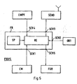
- FIG. 5 schematically shows a vehicle computer FR which is provided for this exemplary embodiment.
- the vehicle computer FR comprises a computing unit RE and a memory SP.
- the vehicle computer FR also has a number of interfaces for connecting other - possibly integrated in the same housing - assemblies.
- a first interface SCH1 is provided for connection of input means EM, such as a keyboard, a voice or a bar code recognition system.
- the input means should at least allow an operator to enter the destination of the vehicle in the computer. Preferably, further information, such as, for example, type and quantity of the charge, can thus also be entered.
- the vehicle computer has a second interface SCH2, via which a location device ORT provides information about the location and possibly also the speed of the vehicle computer.
- the vehicle computer FR further comprises a third interface SCH3 for connecting a transmitter SEND, which transmits at least the location and the destination to a central dispatching computer.
- a receiver EMPF provides information to the vehicle computer FR, which it makes available in the form of data telegrams from track-side transmission facilities, e.g. As line router loops, beacons or radio stations, has received.
- the vehicle computer finally has a fifth interface SCH5 for connecting a vehicle speed controller FGR.
- the arithmetic unit RE in the vehicle computer FR has the task of checking the reliability of the data provided by the receiver and of determining a suitable speed profile on the basis of this data.
- the memory SP is used to store the transmitted data; If appropriate, predetermined speed profiles can also be stored there, from which the arithmetic unit RE selects a suitable profile.
- a vehicle control system FSSYS comprises the vehicle computer FR described above, a receiver EMPF, a transmitter SEND, a location device ORT, input device EM and a cruise control FGR.
Landscapes
- Engineering & Computer Science (AREA)
- Mechanical Engineering (AREA)
- Aviation & Aerospace Engineering (AREA)
- Radar, Positioning & Navigation (AREA)
- Remote Sensing (AREA)
- Physics & Mathematics (AREA)
- General Physics & Mathematics (AREA)
- Automation & Control Theory (AREA)
- Train Traffic Observation, Control, And Security (AREA)
- Traffic Control Systems (AREA)
- Electric Propulsion And Braking For Vehicles (AREA)
- Control Of Position, Course, Altitude, Or Attitude Of Moving Bodies (AREA)
Claims (7)
- Procédé (100) pour la commande d'un véhicule roulant sur rails dans un réseau comprenant les étapes suivantes:a) une destination pour le véhicule est entrée (102) dans un ordinateur de véhicule placé sur le véhicule,b) le véhicule détermine son lieu d'arrêt (103),c) l'ordinateur de véhicule transmet le lieu d'arrêt et la destination à un ordinateur d'ordonnancement (104),d) l'ordinateur d'ordonnancement détermine pour le véhicule un trajet approprié dans le réseau (107), l'ordinateur d'ordonnancement (DR) déterminant, pour une situation de circulation donnée, des trajets optimaux pour chaque véhicule, sur la base des informations convergeant vers lui concernant les lieux d'arrêt, les destinations et les priorités des véhicules se trouvant dans sa zone et, en cas de conflits, accordant la priorité aux véhicules avec une priorité plus élevée et le véhicule transmettant à l'ordinateur d'ordonnancement (DR) chaque modification de son lieu d'arrêt,e) l'ordinateur d'ordonnancement transmet le trajet à mettre au point à au moins un organe de commande (STWA, STWB) etf) le au moins un organe de commande transfère les ordres de commande nécessaires aux éléments de trajet (108) concernés par le réglage du trajet.
- Procédé selon la revendication 1,a) dans lequel les éléments de trajet concernés lancent des télégrammes de données après l'entrée d'un ordre de commande (409),b) dans lequel un récepteur placé sur le véhicule reçoit ces télégrammes de données et l'ordinateur de véhicule analyse (410) les télégrammes de données reçus,c) dans lequel l'ordinateur de véhicule calcule une vitesse en fonction du résultat de cette analyse ou sélectionne (411) un profil de vitesse dans une mémoire contenant plusieurs profils de vitessed) et dans lequel l'ordinateur de véhicule déclenche (412) le réglage de la vitesse du véhicule en fonction de ce profil de vitesse.
- Procédé selon l'une quelconque des revendications précédentes, dans lequel le véhicule transmet à l'ordinateur d'ordonnancement d'autres informations en plus du lieu d'arrêt et de la destination, par exemple, concernant le type et l'état de la charge ou la vitesse.
- Procédé selon l'une quelconque des revendications précédentes, dans lequel le véhicule ne transmet pas à l'ordinateur d'ordonnancement le lieu d'arrêt et la destination de manière sure en terme de technique de signalisation.
- Procédé selon l'une quelconque des revendications précédentes, dans lequel tous les véhicules se trouvant dans une zone géographique du réseau transmettent leur lieu d'arrêt respectif et leur destination respective à l'ordinateur d'ordonnancement qui détermine des trajets pour ces véhicules sur la base de ces informations.
- Ordinateur d'ordonnancement (DR) avec une interface avec au moins un ordinateur de véhicule (FR) et une interface avec un réseau d'information (NETZ) auquel est raccordé au moins un organe de commande (STWA, STWB), caractérisé en ce que cet ordinateur d'ordonnancement est aménagé de manière à ce que- une information sur le lieu et la destination (OUZ) d'un véhicule (F) puisse être reçue par l'ordinateur de véhicule (FR),- un trajet (FW) pour le véhicule (F) puisse être sélectionné à partir de l'information obtenue par l'ordinateur de véhicule (FR) et- un trajet sélectionné puisse être transmis au au moins un organe de commande (STWA, STWB) par le biais de l'interface avec le réseau d'information (NETZ),- pour que le au moins un organe de commande (STWA, STWB) puisse régler les éléments de trajet concernés par le réglage du trajet,
cet ordinateur d'ordonnancement étant aménagé de telle manière qu'un trajet optimal, en particulier à chaque fois un trajet avec le temps de trajet le plus court, soit sélectionné dynamiquement pour chaque véhicule en fonction de modifications apparaissant dans la zone géographique surveillée. - Système pour la commande d'un véhicule (F) roulant sur rails dans un réseau avec au moins un organe de commande (STWA, STWB) et un réseau d'information (NETZ) avec un ordinateur d'ordonnancement (DR) selon la revendication 6.
Applications Claiming Priority (2)
| Application Number | Priority Date | Filing Date | Title |
|---|---|---|---|
| DE19708559 | 1997-03-04 | ||
| DE19708559A DE19708559A1 (de) | 1997-03-04 | 1997-03-04 | Verfahren zur Steuerung spurgebundener Fahrzeuge sowie Fahrzeugrechner und Fahrzeugsteuerungssystem hierfür |
Publications (3)
| Publication Number | Publication Date |
|---|---|
| EP0864478A1 EP0864478A1 (fr) | 1998-09-16 |
| EP0864478B1 EP0864478B1 (fr) | 2003-09-17 |
| EP0864478B2 true EP0864478B2 (fr) | 2007-09-05 |
Family
ID=7822058
Family Applications (1)
| Application Number | Title | Priority Date | Filing Date |
|---|---|---|---|
| EP98440042A Expired - Lifetime EP0864478B2 (fr) | 1997-03-04 | 1998-03-03 | Procédé pour commander des véhicules sur rails ainsi qu'ordinateur pour véhicule et système de commande de véhicule pour ce procédé |
Country Status (3)
| Country | Link |
|---|---|
| EP (1) | EP0864478B2 (fr) |
| AT (1) | ATE249957T1 (fr) |
| DE (2) | DE19708559A1 (fr) |
Families Citing this family (2)
| Publication number | Priority date | Publication date | Assignee | Title |
|---|---|---|---|---|
| US6556898B2 (en) * | 2001-05-18 | 2003-04-29 | Bombardier Transportation Gmbh | Distributed track network control system |
| EP1619102A1 (fr) * | 2004-07-21 | 2006-01-25 | Nedtrain Consulting B.V. | Procédé et système de commande pour un véhicule |
Family Cites Families (7)
| Publication number | Priority date | Publication date | Assignee | Title |
|---|---|---|---|---|
| DE3026652A1 (de) * | 1980-07-14 | 1982-02-11 | Siemens AG, 1000 Berlin und 8000 München | Einrichtung zum energieoptimalen fahren von schienenfahrzeugen in nahverkehrssystemen |
| GB8728165D0 (en) * | 1987-12-02 | 1988-01-06 | Secr Defence | Rail network monitoring and control |
| US5129605A (en) * | 1990-09-17 | 1992-07-14 | Rockwell International Corporation | Rail vehicle positioning system |
| DE4123632A1 (de) * | 1991-07-17 | 1993-01-21 | Ant Nachrichtentech | Informationsuebertragungssystem fuer fahrzeuge und gueter |
| DE4331431C1 (de) * | 1993-09-13 | 1995-03-02 | Elpro Ag | Verkehrsleiteinrichtung zur Steuerung des Fahrbetriebes und des Verkehrsablaufes für den schienengebundenen Verkehr |
| DE4429121C1 (de) * | 1994-08-17 | 1996-02-22 | Siemens Ag | Navigationssystem für ein Fahrzeug |
| JPH08214415A (ja) * | 1995-02-01 | 1996-08-20 | Hitachi Ltd | 構内鉄道の進路設定方法 |
-
1997
- 1997-03-04 DE DE19708559A patent/DE19708559A1/de not_active Withdrawn
-
1998
- 1998-03-03 AT AT98440042T patent/ATE249957T1/de not_active IP Right Cessation
- 1998-03-03 EP EP98440042A patent/EP0864478B2/fr not_active Expired - Lifetime
- 1998-03-03 DE DE59809610T patent/DE59809610D1/de not_active Expired - Lifetime
Non-Patent Citations (1)
| Title |
|---|
| Dokumentation "Zugsicherungs-/Zugsteuerungssystem ETCS, Functional Requirements Specification" Teil B u. Teil E, Projekt DEUFRAKO-M, vom 31.8.1994 † |
Also Published As
| Publication number | Publication date |
|---|---|
| DE19708559A1 (de) | 1998-09-10 |
| DE59809610D1 (de) | 2003-10-23 |
| EP0864478A1 (fr) | 1998-09-16 |
| EP0864478B1 (fr) | 2003-09-17 |
| ATE249957T1 (de) | 2003-10-15 |
Similar Documents
| Publication | Publication Date | Title |
|---|---|---|
| EP2013065B1 (fr) | Systeme de transport actif sur rails | |
| DE19726542B4 (de) | Verfahren zur Steuerung und Sicherung eines fahrplangebundenen Verkehrssystems | |
| DE602004000115T2 (de) | Zugsicherungsverfahren und-system, speziell des Typs ERTMS | |
| EP0958987B1 (fr) | Procédé de fonctionnement de véhicules ferroviaires et centrale de commande de train pour cela | |
| DE69307494T3 (de) | Eisenbahnanmeldeanlage | |
| EP1789298B2 (fr) | Procede et dispositif permettant le fonctionnement coordonne de portes de vehicules ferroviaires ou guides sur rails et de systemes de guidage de quai correspondants, en particulier de portes de quai | |
| DE2330366A1 (de) | Fahrzeugsteuersystem | |
| EP1208027B1 (fr) | Chemin de fer electrique suspendu | |
| DE10018967C1 (de) | Funkbasiertes Zugsicherungssystem für ein von einer Mehrzahl von Zügen befahrbares Bahn-Streckennetz | |
| EP2885189B1 (fr) | Système de transport bimodal | |
| WO2015128148A1 (fr) | Procédé et ensemble permettant de faire fonctionner des véhicules guidés sur rails et commandés par radio | |
| DE2926149A1 (de) | Geraet und verfahren zum bestimmen der fahrgeschwindigkeit eines fahrzeuges in bezug auf eine gewuenschte stopposition | |
| EP1556266A1 (fr) | Systeme de transport guide et procede de commande des vehicules d'un systeme de transport guide | |
| DE4331431C1 (de) | Verkehrsleiteinrichtung zur Steuerung des Fahrbetriebes und des Verkehrsablaufes für den schienengebundenen Verkehr | |
| DE3026652A1 (de) | Einrichtung zum energieoptimalen fahren von schienenfahrzeugen in nahverkehrssystemen | |
| EP0864478B2 (fr) | Procédé pour commander des véhicules sur rails ainsi qu'ordinateur pour véhicule et système de commande de véhicule pour ce procédé | |
| DE102019215937A1 (de) | Fahrwerk für eine Gondel eines Gondelbahnsystems, Tragmittel für Gondeln eines Gondelbahnsystems, Gondel für ein Gondelbahnsystem, Gondelbahnsystem und Verfahren zum Ansteuern eines Fahrwerks | |
| DE2149943A1 (de) | Regelungsvorrichtung fuer Fahrzeuge | |
| DE2114608B2 (de) | Einrichtung zur regelung eines verkehrssystems | |
| DE102004057907A1 (de) | Verfahren bei der Einbindung von Rangiervorgängen bei der Zugsteuerung und Zugsicherung mittels bidirektionaler Funk-Informationsübertragung | |
| DE3722295A1 (de) | Einrichtung zum betrieb einer bahn mit langstator-linearmotor | |
| DE2528463A1 (de) | Steuerung des antriebes und/oder der bremse von triebfahrzeugen | |
| DE3434268A1 (de) | Verfahren zur dezentralen steuerung von streckengebundenen fahrzeugen und fahrzeugfunktionen | |
| DE102004062987A1 (de) | Verfahren zur Realisierung eines virtuellen Streckenblocks unter Nutzung funkgesteuerter Fahrwegelemente | |
| EP4071028B1 (fr) | Prévention d'une collision d'un véhicule ferroviaire à une intersection dans un systeme cbtc |
Legal Events
| Date | Code | Title | Description |
|---|---|---|---|
| PUAI | Public reference made under article 153(3) epc to a published international application that has entered the european phase |
Free format text: ORIGINAL CODE: 0009012 |
|
| AK | Designated contracting states |
Kind code of ref document: A1 Designated state(s): AT BE CH DE ES FR GB IT LI SE |
|
| AX | Request for extension of the european patent |
Free format text: AL;LT;LV;MK;RO;SI |
|
| 17P | Request for examination filed |
Effective date: 19980725 |
|
| RAP3 | Party data changed (applicant data changed or rights of an application transferred) |
Owner name: ALCATEL |
|
| RAP3 | Party data changed (applicant data changed or rights of an application transferred) |
Owner name: ALCATEL |
|
| AKX | Designation fees paid |
Free format text: AT BE CH DE ES FR GB IT LI SE |
|
| RBV | Designated contracting states (corrected) |
Designated state(s): AT BE CH DE ES FR GB IT LI SE |
|
| 17Q | First examination report despatched |
Effective date: 20020715 |
|
| GRAH | Despatch of communication of intention to grant a patent |
Free format text: ORIGINAL CODE: EPIDOS IGRA |
|
| GRAS | Grant fee paid |
Free format text: ORIGINAL CODE: EPIDOSNIGR3 |
|
| GRAA | (expected) grant |
Free format text: ORIGINAL CODE: 0009210 |
|
| AK | Designated contracting states |
Kind code of ref document: B1 Designated state(s): AT BE CH DE ES FR GB IT LI SE |
|
| REG | Reference to a national code |
Ref country code: GB Ref legal event code: FG4D Free format text: NOT ENGLISH |
|
| REG | Reference to a national code |
Ref country code: CH Ref legal event code: EP |
|
| REF | Corresponds to: |
Ref document number: 59809610 Country of ref document: DE Date of ref document: 20031023 Kind code of ref document: P |
|
| GBT | Gb: translation of ep patent filed (gb section 77(6)(a)/1977) |
Effective date: 20031112 |
|
| PG25 | Lapsed in a contracting state [announced via postgrant information from national office to epo] |
Ref country code: SE Free format text: LAPSE BECAUSE OF FAILURE TO SUBMIT A TRANSLATION OF THE DESCRIPTION OR TO PAY THE FEE WITHIN THE PRESCRIBED TIME-LIMIT Effective date: 20031217 |
|
| PG25 | Lapsed in a contracting state [announced via postgrant information from national office to epo] |
Ref country code: ES Free format text: LAPSE BECAUSE OF FAILURE TO SUBMIT A TRANSLATION OF THE DESCRIPTION OR TO PAY THE FEE WITHIN THE PRESCRIBED TIME-LIMIT Effective date: 20031228 |
|
| PG25 | Lapsed in a contracting state [announced via postgrant information from national office to epo] |
Ref country code: AT Free format text: LAPSE BECAUSE OF NON-PAYMENT OF DUE FEES Effective date: 20040303 |
|
| PG25 | Lapsed in a contracting state [announced via postgrant information from national office to epo] |
Ref country code: LI Free format text: LAPSE BECAUSE OF NON-PAYMENT OF DUE FEES Effective date: 20040331 Ref country code: CH Free format text: LAPSE BECAUSE OF NON-PAYMENT OF DUE FEES Effective date: 20040331 Ref country code: BE Free format text: LAPSE BECAUSE OF NON-PAYMENT OF DUE FEES Effective date: 20040331 |
|
| PLBQ | Unpublished change to opponent data |
Free format text: ORIGINAL CODE: EPIDOS OPPO |
|
| PLBI | Opposition filed |
Free format text: ORIGINAL CODE: 0009260 |
|
| ET | Fr: translation filed | ||
| PLAX | Notice of opposition and request to file observation + time limit sent |
Free format text: ORIGINAL CODE: EPIDOSNOBS2 |
|
| 26 | Opposition filed |
Opponent name: DEUTSCHE BAHN AG Effective date: 20040617 |
|
| BERE | Be: lapsed |
Owner name: *ALCATEL Effective date: 20040331 |
|
| PLBB | Reply of patent proprietor to notice(s) of opposition received |
Free format text: ORIGINAL CODE: EPIDOSNOBS3 |
|
| REG | Reference to a national code |
Ref country code: CH Ref legal event code: PL |
|
| PLAB | Opposition data, opponent's data or that of the opponent's representative modified |
Free format text: ORIGINAL CODE: 0009299OPPO |
|
| PLAB | Opposition data, opponent's data or that of the opponent's representative modified |
Free format text: ORIGINAL CODE: 0009299OPPO |
|
| R26 | Opposition filed (corrected) |
Opponent name: DEUTSCHE BAHN AG Effective date: 20040617 |
|
| R26 | Opposition filed (corrected) |
Opponent name: DEUTSCHE BAHN AG Effective date: 20040617 |
|
| RAP2 | Party data changed (patent owner data changed or rights of a patent transferred) |
Owner name: ALCATEL LUCENT |
|
| PUAH | Patent maintained in amended form |
Free format text: ORIGINAL CODE: 0009272 |
|
| STAA | Information on the status of an ep patent application or granted ep patent |
Free format text: STATUS: PATENT MAINTAINED AS AMENDED |
|
| 27A | Patent maintained in amended form |
Effective date: 20070905 |
|
| AK | Designated contracting states |
Kind code of ref document: B2 Designated state(s): AT BE CH DE ES FR GB IT LI SE |
|
| GBTA | Gb: translation of amended ep patent filed (gb section 77(6)(b)/1977) | ||
| REG | Reference to a national code |
Ref country code: ES Ref legal event code: FD2A Effective date: 20040304 |
|
| EN | Fr: translation not filed | ||
| ET3 | Fr: translation filed ** decision concerning opposition | ||
| REG | Reference to a national code |
Ref country code: FR Ref legal event code: EERR Free format text: CORRECTION DE BOPI 08/18 - BREVETS EUROPEENS DONT LA TRADUCTION N A PAS ETE REMISE A L INPI. IL Y A LIEU DE SUPPRIMER : LA MENTION DE LA NON-REMISE. LA REMISE DE LA TRADUCTION EST PUBLIEE DANS LE PRESENT BOPI. |
|
| PG25 | Lapsed in a contracting state [announced via postgrant information from national office to epo] |
Ref country code: FR Free format text: LAPSE BECAUSE OF FAILURE TO SUBMIT A TRANSLATION OF THE DESCRIPTION OR TO PAY THE FEE WITHIN THE PRESCRIBED TIME-LIMIT Effective date: 20080502 |
|
| REG | Reference to a national code |
Ref country code: FR Ref legal event code: CA Effective date: 20150521 |
|
| REG | Reference to a national code |
Ref country code: FR Ref legal event code: CA Effective date: 20150521 |
|
| REG | Reference to a national code |
Ref country code: FR Ref legal event code: PLFP Year of fee payment: 19 |
|
| REG | Reference to a national code |
Ref country code: FR Ref legal event code: PLFP Year of fee payment: 20 |
|
| PGFP | Annual fee paid to national office [announced via postgrant information from national office to epo] |
Ref country code: FR Payment date: 20170313 Year of fee payment: 20 Ref country code: DE Payment date: 20170307 Year of fee payment: 20 |
|
| PGFP | Annual fee paid to national office [announced via postgrant information from national office to epo] |
Ref country code: GB Payment date: 20170228 Year of fee payment: 20 |
|
| PGFP | Annual fee paid to national office [announced via postgrant information from national office to epo] |
Ref country code: IT Payment date: 20170320 Year of fee payment: 20 |
|
| REG | Reference to a national code |
Ref country code: DE Ref legal event code: R071 Ref document number: 59809610 Country of ref document: DE |
|
| REG | Reference to a national code |
Ref country code: GB Ref legal event code: PE20 Expiry date: 20180302 |
|
| PG25 | Lapsed in a contracting state [announced via postgrant information from national office to epo] |
Ref country code: GB Free format text: LAPSE BECAUSE OF EXPIRATION OF PROTECTION Effective date: 20180302 |