EP0864522B1 - Bogenverteilungsvorrichtung - Google Patents
Bogenverteilungsvorrichtung Download PDFInfo
- Publication number
- EP0864522B1 EP0864522B1 EP98301810A EP98301810A EP0864522B1 EP 0864522 B1 EP0864522 B1 EP 0864522B1 EP 98301810 A EP98301810 A EP 98301810A EP 98301810 A EP98301810 A EP 98301810A EP 0864522 B1 EP0864522 B1 EP 0864522B1
- Authority
- EP
- European Patent Office
- Prior art keywords
- sheet
- distribution device
- conveying means
- conveying
- sheet distribution
- Prior art date
- Legal status (The legal status is an assumption and is not a legal conclusion. Google has not performed a legal analysis and makes no representation as to the accuracy of the status listed.)
- Expired - Lifetime
Links
Images






Classifications
-
- B—PERFORMING OPERATIONS; TRANSPORTING
- B65—CONVEYING; PACKING; STORING; HANDLING THIN OR FILAMENTARY MATERIAL
- B65H—HANDLING THIN OR FILAMENTARY MATERIAL, e.g. SHEETS, WEBS, CABLES
- B65H31/00—Pile receivers
- B65H31/24—Pile receivers multiple or compartmented, e.d. for alternate, programmed, or selective filling
-
- B—PERFORMING OPERATIONS; TRANSPORTING
- B65—CONVEYING; PACKING; STORING; HANDLING THIN OR FILAMENTARY MATERIAL
- B65H—HANDLING THIN OR FILAMENTARY MATERIAL, e.g. SHEETS, WEBS, CABLES
- B65H29/00—Delivering or advancing articles from machines; Advancing articles to or into piles
- B65H29/24—Delivering or advancing articles from machines; Advancing articles to or into piles by air blast or suction apparatus
- B65H29/241—Suction devices
- B65H29/242—Suction bands or belts
-
- B—PERFORMING OPERATIONS; TRANSPORTING
- B65—CONVEYING; PACKING; STORING; HANDLING THIN OR FILAMENTARY MATERIAL
- B65H—HANDLING THIN OR FILAMENTARY MATERIAL, e.g. SHEETS, WEBS, CABLES
- B65H39/00—Associating, collating, or gathering articles or webs
- B65H39/10—Associating articles from a single source, to form, e.g. a writing-pad
-
- B—PERFORMING OPERATIONS; TRANSPORTING
- B65—CONVEYING; PACKING; STORING; HANDLING THIN OR FILAMENTARY MATERIAL
- B65H—HANDLING THIN OR FILAMENTARY MATERIAL, e.g. SHEETS, WEBS, CABLES
- B65H2408/00—Specific machines
- B65H2408/10—Specific machines for handling sheet(s)
- B65H2408/11—Sorters or machines for sorting articles
- B65H2408/112—Sorters or machines for sorting articles with stationary location in space of the bins and in-feed member movable from bin to bin
-
- B—PERFORMING OPERATIONS; TRANSPORTING
- B65—CONVEYING; PACKING; STORING; HANDLING THIN OR FILAMENTARY MATERIAL
- B65H—HANDLING THIN OR FILAMENTARY MATERIAL, e.g. SHEETS, WEBS, CABLES
- B65H2408/00—Specific machines
- B65H2408/10—Specific machines for handling sheet(s)
- B65H2408/11—Sorters or machines for sorting articles
- B65H2408/118—Combination of several sorting modules
-
- B—PERFORMING OPERATIONS; TRANSPORTING
- B65—CONVEYING; PACKING; STORING; HANDLING THIN OR FILAMENTARY MATERIAL
- B65H—HANDLING THIN OR FILAMENTARY MATERIAL, e.g. SHEETS, WEBS, CABLES
- B65H2801/00—Application field
- B65H2801/03—Image reproduction devices
- B65H2801/06—Office-type machines, e.g. photocopiers
Definitions
- the present invention relates to a sheet distribution device, particularly to an interconnectable sheet distribution device which is provided with a first conveying means for receiving an image formed sheet from a printer, a copying machine or another image forming device to convey the sheet to a body and a second conveying means for receiving the image formed sheet from the first conveying means to convey the sheet to each of plural distribution bins.
- a slave sorter unit in order to increase the number of distribution bins as required, can be optionally interconnected to a main sorter unit having the aforementioned constitution.
- the slave sorter unit is provided with plural distribution bins similar to those of the main sorter unit, a sheet conveying portion similar to the aforementioned second conveying portion and an indexer which can vertically move in the same manner as in the main sorter unit.
- an upper portion of the main sorter unit to which the slave sorter unit can be interconnected is provided with a third conveying portion for transferring the printed sheet from the first conveying portion in a horizontal direction to a region above a top distribution bin of the slave sorter unit.
- the third conveying portion is fixed beforehand to the main sorter unit. Also, in order to increase the number of distribution bins by interconnecting a second slave sorter unit to the slave sorter unit, the sheet conveying portion similar to the third conveying portion is fixed beforehand to the slave sorter unit.
- the unnecessary third conveying portion is provided. This fails to reduce the cost per sorter unit. Also, when the main sorter unit and the slave sorter unit are constituted of a sorter unit for common use, the first conveying portion needs to be removed from the slave sorter unit. The operation is thus complicated. Further, since the main sorter unit is different in configuration from the slave sorter unit, a package box needs to be prepared for each of the units. This is also a factor of cost increase.
- a sorter according to the preamble of the appended claim 1 is disclosed in prior art document EP 0 200 240 A.
- this known sorter has first conveying means which merely extends telescopically at a fixed height from the sorter body.
- the sorter may not therefore be conveniently used with a range of image forming devices having sheet discharge portions arranged at varying heights.
- an object of the invention is to provide a sheet distribution device in which by combining a first conveying portion and a third conveying portion (junction conveying portion) for use, a manufacture cost per unit of sheet distribution device is reduced, while an operational process for interconnecting sheet distribution devices is simplified.
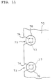
- the engagement means is constituted of an engagement groove formed in a tip end bottom of the first conveying means and an engaging pin formed on an inner side in the space for engaging with the engagement groove when the first conveying means is inserted.
- the engaging pin has an engaging groove formed therein for engaging with a peripheral edge of the engagement groove.
- Fig. 1 is a diagrammatic side view showing that a sheet distribution device according to the invention is connected to an image forming device.
- Fig. 2 is a diagrammatic side view showing an inner structure of a main sorter unit of Fig. 1 in a perspective manner.
- Fig. 3 is a side view showing a vicinity of a curved portion of a conveying means.
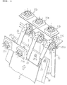
- Fig. 4 is an exploded perspective view showing the vicinity of the curved portion of the conveying means.
- Fig. 5 is a plan view of a distribution bin in the sheet distribution device.
- Fig. 6 is an enlarged perspective view showing a sheet matching member and a sheet bunch pushing member.
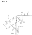
- Fig. 8 is a diagrammatic side view showing an attachment structure of a proximal end portion of a first conveying portion.
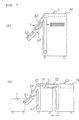
- Figs. 9A and 9B are explanatory views showing an attitude of a downstream-side conveying port-ion when the sheet distribution device is used as the main sorter unit or a slave sorter unit.
- Figs. 1 and 2 show an entire constitution of the sheet distribution device: Fig. 1 is a diagrammatic side view showing a constitution in which the sheet distribution device is connected to an image forming device; and Fig. 2 is a diagrammatic side view showing an inner structure of a main sorter unit of Fig. 1 in a perspective manner.
- a sheet distribution device S is provided with plural distribution bins 4 constituted of plural, e.g., fifty trays vertically arranged with predetermined intervals kept thereamong in a fixed position in a frame 3 for successively receiving an image formed or printed sheet 2 (Fig.
- the conveying means 5 is constituted of a first conveying portion 5A for conveying the sheet 2 discharged from a discharge portion of the image forming device 1 obliquely upward to an upper portion of a body, a second conveying portion 5B for conveying the sheet 2 from the upper portion downward to the indexer 6, and a curved portion 5C provided on an upper end of the second conveying portion 5B for receiving the sheet 2 from the first conveying portion 5A and curving the sheet 2 in a conveying direction at an acute angle.
- the first conveying portion 5A is divided into an upstream conveying portion and a downstream conveying portion.
- a perforated conveying belt 9 is extended between belt pulleys 20a and 20b on both ends, and suction blowers 8 are disposed inside the conveying belt 9, so that the rear face of the sheet 2 is drawn and held during conveying.
- a perforated conveying belt 10 is extended directly from a belt pulley 16 to a belt pulley 17 of the second conveying portion 5B, so that the sheet 2 can be smoothly delivered from the first conveying portion 5A to the second conveying portion 5B without the sheet 2 skewing between the conveying portions 5A and 5B.
- a plurality of small press rollers 22a and 22b with saw teeth formed on peripheral faces are arranged in a transverse direction.
- the press rollers 22a and 22b press and prevent the tip end of the sheet 2 from bouncing up.
- the press rollers 22a and 22b are effectively operative, especially, for conveying a thick sheet. Additionally, the press rollers 22a and 22b can be selectively operated in accordance with the types of sheets to be conveyed.
- a space 19 for storing the third conveying portion 5D is horizontally formed in the upper portion of the sheet distribution device S.
- the first conveying portion 5A of the slave machine S1 can be inserted and fixed in the space 19 so that the plural sheet distribution devices S can be connected.
- the image forming device 1 is provided with a discharged sheet base 13 for accumulating the discharged sheets 2 when they are not sorted. Also, on an outer wall face of the sheet distribution device S attached is an outside electromotive stapler 15.
- a light emission sensor 23a and a light receiving sensor 23b are provided in the vicinity of the receiving end of the top distribution bin 4 and the receiving end of the lowermost distribution bin 4.
- the light emission sensor 23a detects that the sheet 2 fed from the indexer 6 is stored in the distribution bin 4, while the light receiving sensor 23b detects that a bunch of sheets are pushed out to a position in which the bunch can be stapled.
- the distribution bin 4 is a rectangular flat plate, and has in one side a large notched portion 24 via which the sheet 2 can be easily taken out. Also, on a top face of the distribution bin 4 disposed is a substantially V-shaped sheet support plate 25 which is protruded to a middle portion of the notched portion 24 to prevent the sheet 2 from hanging down.
- two large openings 26 and 27 are formed on the opposite side of the notched portion 24, and further an elongated guide hole 28 is formed in a back to forth direction in the middle portion.
- matching members are disposed in the notched portion 24, the openings 26, 27 and the guide hole 28, respectively, so that the sheet 2 is matched with two reference positions L1 and L2.
- the first matching member 29 housed in the sheet taking-out door 31 is operated by a linkage 34.
- the linkage 34 is contracted and housed in the door 31.
- the linkage 34 is expanded.
- one side edge of the sheet 2 is pushed out by a pair of vertically long matching plates 35a and 35b which are mounted on tip ends of the linkage 34.
- the first matching member 29 is operated by a screw shaft 36 rotated by a motor (not shown) and a nut 37 which slides on the shaft 36.
- the operating portion is provided in the lower portion of the sheet taking-out door 31.
- a third matching member 40 is provided in the middle guide hole 28 for pushing the discharge tip end of the sheet 2 to match the sheet 2 with the reference position L2 along a vertical wall 4a which is built on the sheet receiving end of the distribution bin 4.
- the third matching member 40 is constituted of a guide rail 41 having a U-shaped cross section which is vertically passed through the distribution bin 4.
- the guide rail 41 has flat vertical faces 42a and 42b on its edges of an opening.
- the vertical faces 42a and 42b are opposed to each other on the sheet receiving end of the distribution bin 4.
- Elastic members 43a and 43b formed of sponge or the like are placed along lengths of the vertical faces 42a and 42b.
- a string-like stopper member 45 is extended vertically in front of the third matching member 40.
- the stopper member 45 elastically thrusts at the discharge tip end of the printed sheet 2 ejected from the indexer 6 toward the distribution bin 4 to moderately stop the sheet 2.
- two bands 46a and 46b formed of rubber which provides a larger damper effect than sponge.
- upper ends of the rubber bands 46a and 46b are rotatably attached to tip ends of levers 47a and 47b.
- a sheet bunch pushing member 50 is provided in front of the guide rail 41. After all the sheets 2 are delivered and distributed by the indexer 6, to staple the sheets as a post-processing, the sheet bunch pushing member 50 pushes out a bunch of sheets accumulated on the distribution bin 4 to an elevating/lowering passage of the indexer 6.
- the sheet bunch pushing member 50 is constituted of a body 52 having a pushing face 51 on its front end, and rotatable engaging members 53a and 53b provided on opposite sides of the pushing face 51 for engaging with opposite side edges 28a and 28b of the guide hole 28. When the engaging members 53a and 53b are rotated inwardly relative to each other, they are disengaged from the side edges 28a and 28b of the guide hole 28.
- the third conveying means 5D can be formed on the main sorter unit S1.
- the attachment is remarkably easy.
Landscapes
- Engineering & Computer Science (AREA)
- Mechanical Engineering (AREA)
- Collation Of Sheets And Webs (AREA)
Claims (7)
- Blattverteilungsvorrichtung, die mit einer ersten Fördereinrichtung (5A), die ein mit Bild versehenes Blatt (2) von einer Bildherstellungsvorrichtung (1) empfängt und das mit Bild versehene Blatt in einen Hauptkörper der Blattverteilungsvorrichtung hinein befördert, sowie mit einer zweiten Förderreinrichtung (5B) ausgestattet ist, die das mit Bild versehene Blatt (2) von der ersten Fördereinrichtung (5A) empfängt und das mit Bild versehene Blatt (2) zu jedem von mehreren Verteilungsbehältem (4) befördert, wobei die Blattverteilungsvorrichtung mit einer weiteren Blattverteilungsvorrichtung verbunden werden kann und sich die weitere Blattverteilungsvorrichtung bei Verbindung mit der weiteren Blattverteilungsvorrichtung in Bezug auf die Blattförderrichtung stromab von der Blattverteilungsvorrichtung befindet, und die erste Fördereinrichtung (5A) der weiteren Blattverteilungsvorrichtung als Verbindungs-Fördereinrichtung (5D) dient, die das Blatt (2) von der Blattverteilungsvorrichtung zu der weiteren Blattverteilungsvorrichtung befördert, wobei die Blattverteilungsvorrichtung (S) einen Raum zur Aufbewahrung der Verbindungs-Fördereinrichtung (5D) der weiteren Blattverteilungsvorrichtung bei Verbindung der Blattverteilungsvorrichtungen aufweist, und die Blattverteilungsvorrichtung dadurch gekennzeichnet ist, dass die erste Fördereinrichtung (5A) an einem stromabliegenden Ende derselben von einer Trägerachse (62), die an dem Gehäuse der Blattverteilungsvorrichtung befestigt ist, drehbar getragen wird und, wenn die Blattverteilungsvorrichtungen verbunden sind, in der Nähe eines Bereiches gedreht werden kann, in dem das Blatt (2) zu der zweiten Fördereinrichtung (5B) der Blattverteilungsvorrichtung überführt wird, die sich in Bezug auf die Blattförderrichtung stromauf befindet.
- Blattverteilungsvorrichtung nach Anspruch 1, wobei die erste Fördereinrichtung (5A) und die zweite Fördereinrichtung (5B) über ein Blattförderband (10) direkt verbunden sind.
- Blattverteilungsvorrichtung nach Anspruch 1, die mit einem Trägerelement ausgestattet ist, das eine gedrehte Position der ersten Fördereinrichtung (5A) hält.
- Blattverteilungsvorrichtung nach Anspruch 1, die mit einem Umschaltmechanismus (12) ausgestattet ist, der das mit Bild versehene Blatt (2), das von der ersten Fördereinrichtung (5A) befördert wird, entweder zu der zweiten Fördereinrichtung (5B) oder der Verbindungs-Fördereinrichtung überführt.
- Blattverteilungsvorrichtung nach Anspruch 1, die mit einer Eingriffseinrichtung ausgestattet ist, die die erste Fördereinrichtung (5A) in dem Raum fixiert, wenn die Blattverteilungsvorrichtungen (S) miteinander verbunden sind und die erste Fördereinrichtung (5A) der Blattverteilungsvorrichtung (S) an der stromabliegenden Seite in den Raum in der Blattverteilungsvorrichtung (S) an der stromaufliegenden Seite der Blattfördereinrichtung eingeführt wird.
- Blattverteilungsvorrichtung nach Anspruch 5, wobei die Eingriffseinrichtung aus einer Eingriffsnut (73), die in einer Unterseite am vorderen Ende der ersten Fördereinrichtung (5A) ausgebildet ist, und einem Eingriffsbolzen (76) besteht, der an einer Innenseite in dem Raum ausgebildet ist, um in die Eingriffsnut (73) einzugreifen, wenn die erste Fördereinrichtung (5A) eingeführt wird.
- Blattverteilungsvorrichtung nach Anspruch 6, wobei in dem Eingriffsbolzen (76) eine Eingriffsnut (77) ausgebildet ist, die mit einer Umfangskante der Eingriffsnut (73) in Eingriff kommt.
Applications Claiming Priority (3)
| Application Number | Priority Date | Filing Date | Title |
|---|---|---|---|
| JP7886197 | 1997-03-12 | ||
| JP78861/97 | 1997-03-12 | ||
| JP07886197A JP3621551B2 (ja) | 1997-03-12 | 1997-03-12 | シート分配装置 |
Publications (3)
| Publication Number | Publication Date |
|---|---|
| EP0864522A2 EP0864522A2 (de) | 1998-09-16 |
| EP0864522A3 EP0864522A3 (de) | 1999-04-07 |
| EP0864522B1 true EP0864522B1 (de) | 2001-10-10 |
Family
ID=13673619
Family Applications (1)
| Application Number | Title | Priority Date | Filing Date |
|---|---|---|---|
| EP98301810A Expired - Lifetime EP0864522B1 (de) | 1997-03-12 | 1998-03-11 | Bogenverteilungsvorrichtung |
Country Status (4)
| Country | Link |
|---|---|
| US (1) | US6126162A (de) |
| EP (1) | EP0864522B1 (de) |
| JP (1) | JP3621551B2 (de) |
| DE (1) | DE69801942T2 (de) |
Families Citing this family (5)
| Publication number | Priority date | Publication date | Assignee | Title |
|---|---|---|---|---|
| US7380779B2 (en) * | 2003-10-16 | 2008-06-03 | Canon Kabushiki Kaisha | Sheet processing system |
| JP4185843B2 (ja) * | 2003-10-16 | 2008-11-26 | キヤノン株式会社 | シート処理システム |
| JP2011251788A (ja) * | 2010-05-31 | 2011-12-15 | Toshiba Tec Corp | 用紙排出装置、用紙排出方法、画像形成装置および画像形成方法 |
| JP5133375B2 (ja) * | 2010-07-12 | 2013-01-30 | 東芝テック株式会社 | 用紙排出装置、用紙排出方法、画像形成装置および画像形成方法 |
| JP6010061B2 (ja) * | 2014-02-28 | 2016-10-19 | 日本電産コパル株式会社 | レーザーマーキング装置 |
Family Cites Families (12)
| Publication number | Priority date | Publication date | Assignee | Title |
|---|---|---|---|---|
| US3848867A (en) * | 1972-09-20 | 1974-11-19 | Norfin | No-counter sorter-stacker |
| US4750731A (en) * | 1981-08-14 | 1988-06-14 | Canon Kabushiki Kaisha | Sheet storing appartus |
| US4451031A (en) * | 1982-01-18 | 1984-05-29 | Mccain Manufacturing Corporation | Signature machines |
| US4561647A (en) * | 1984-02-13 | 1985-12-31 | Snellman Donald L | Sheet deflector and conveyor drive |
| JPH0669863B2 (ja) * | 1984-10-04 | 1994-09-07 | ミノルタカメラ株式会社 | ソ−タ |
| NL8500929A (nl) * | 1985-03-29 | 1986-10-16 | Oce Nederland B V Patents And | Vellensorteerinrichting. |
| KR880002054A (ko) * | 1986-07-28 | 1988-04-28 | 이석형 | 복사지 분류장치 |
| US4974828A (en) * | 1986-08-20 | 1990-12-04 | Canon Kabushiki Kaisha | Sheet stacking apparatus |
| JP2736817B2 (ja) * | 1990-06-08 | 1998-04-02 | ニスカ株式会社 | ステップリング機構付きソータ |
| JP3500164B2 (ja) * | 1992-05-19 | 2004-02-23 | 理想科学工業株式会社 | 孔版印刷装置 |
| JPH09301619A (ja) * | 1996-05-13 | 1997-11-25 | Nisca Corp | シート分配装置 |
| JP3659734B2 (ja) * | 1996-05-13 | 2005-06-15 | 理想科学工業株式会社 | 画像形成システム |
-
1997
- 1997-03-12 JP JP07886197A patent/JP3621551B2/ja not_active Expired - Fee Related
-
1998
- 1998-03-06 US US09/036,231 patent/US6126162A/en not_active Expired - Fee Related
- 1998-03-11 DE DE69801942T patent/DE69801942T2/de not_active Expired - Fee Related
- 1998-03-11 EP EP98301810A patent/EP0864522B1/de not_active Expired - Lifetime
Also Published As
| Publication number | Publication date |
|---|---|
| DE69801942T2 (de) | 2002-04-04 |
| DE69801942D1 (de) | 2001-11-15 |
| EP0864522A2 (de) | 1998-09-16 |
| JP3621551B2 (ja) | 2005-02-16 |
| US6126162A (en) | 2000-10-03 |
| JPH10250916A (ja) | 1998-09-22 |
| EP0864522A3 (de) | 1999-04-07 |
Similar Documents
| Publication | Publication Date | Title |
|---|---|---|
| US4817934A (en) | Dual tote sorter and stacker | |
| CN1202642A (zh) | 输纸系统 | |
| US5324024A (en) | Paper discharging apparatus | |
| US6755411B2 (en) | Envelope transport module with vacuum ports for use in an envelope inserting machine | |
| US6206361B1 (en) | Device for separating blanks | |
| EP0864522B1 (de) | Bogenverteilungsvorrichtung | |
| AU2001295354B2 (en) | Device for processing printing products | |
| US6776412B2 (en) | Removable sheet feeder with jam clearance for use in an envelope inserting machine | |
| US6073926A (en) | Sheet discharge device | |
| US6227529B1 (en) | Sheet distribution device | |
| JPS60248566A (ja) | 可動トレイ型ソ−タ | |
| US6908080B2 (en) | Device for forming and conveying away a sheet stack with the aid of a separating mechanism | |
| EP0807535B1 (de) | Mit einer Heftvorrichtung versehenes Blattsortiergerät | |
| EP0807593B1 (de) | Blattübergabesystem | |
| JP3621577B2 (ja) | シート分配装置 | |
| JPS63196450A (ja) | 可動トレイ型ソ−タ | |
| JP3661960B2 (ja) | シート分配装置 | |
| JP3055037B2 (ja) | 用紙分配装置 | |
| US20030146562A1 (en) | Reloading Device for Stacks of Sheets of Paper, Plastic Material, or the Like and Method for Operating such Reloading Device | |
| WO1989006634A1 (en) | Paper sheet sorting apparatus | |
| CN1894148B (zh) | 带有气体助落功能的印刷片材输送机 | |
| JPH08169610A (ja) | シート材搬送積載装置 | |
| JPH0632921Y2 (ja) | 案内つき丁合装置 | |
| JP2000272807A (ja) | 選択的用紙受渡し装置 | |
| JPH08127463A (ja) | 用紙搬送装置 |
Legal Events
| Date | Code | Title | Description |
|---|---|---|---|
| PUAI | Public reference made under article 153(3) epc to a published international application that has entered the european phase |
Free format text: ORIGINAL CODE: 0009012 |
|
| AK | Designated contracting states |
Kind code of ref document: A2 Designated state(s): DE FR GB |
|
| AX | Request for extension of the european patent |
Free format text: AL;LT;LV;MK;RO;SI |
|
| PUAL | Search report despatched |
Free format text: ORIGINAL CODE: 0009013 |
|
| AK | Designated contracting states |
Kind code of ref document: A3 Designated state(s): AT BE CH DE DK ES FI FR GB GR IE IT LI LU MC NL PT SE |
|
| AX | Request for extension of the european patent |
Free format text: AL;LT;LV;MK;RO;SI |
|
| 17P | Request for examination filed |
Effective date: 19990920 |
|
| AKX | Designation fees paid |
Free format text: DE FR GB |
|
| 17Q | First examination report despatched |
Effective date: 19991118 |
|
| GRAG | Despatch of communication of intention to grant |
Free format text: ORIGINAL CODE: EPIDOS AGRA |
|
| GRAG | Despatch of communication of intention to grant |
Free format text: ORIGINAL CODE: EPIDOS AGRA |
|
| GRAH | Despatch of communication of intention to grant a patent |
Free format text: ORIGINAL CODE: EPIDOS IGRA |
|
| GRAH | Despatch of communication of intention to grant a patent |
Free format text: ORIGINAL CODE: EPIDOS IGRA |
|
| GRAA | (expected) grant |
Free format text: ORIGINAL CODE: 0009210 |
|
| AK | Designated contracting states |
Kind code of ref document: B1 Designated state(s): DE FR GB |
|
| REF | Corresponds to: |
Ref document number: 69801942 Country of ref document: DE Date of ref document: 20011115 |
|
| REG | Reference to a national code |
Ref country code: GB Ref legal event code: IF02 |
|
| ET | Fr: translation filed | ||
| PLBE | No opposition filed within time limit |
Free format text: ORIGINAL CODE: 0009261 |
|
| STAA | Information on the status of an ep patent application or granted ep patent |
Free format text: STATUS: NO OPPOSITION FILED WITHIN TIME LIMIT |
|
| 26N | No opposition filed | ||
| PGFP | Annual fee paid to national office [announced via postgrant information from national office to epo] |
Ref country code: GB Payment date: 20090311 Year of fee payment: 12 |
|
| PGFP | Annual fee paid to national office [announced via postgrant information from national office to epo] |
Ref country code: DE Payment date: 20090313 Year of fee payment: 12 |
|
| PGFP | Annual fee paid to national office [announced via postgrant information from national office to epo] |
Ref country code: FR Payment date: 20090316 Year of fee payment: 12 |
|
| GBPC | Gb: european patent ceased through non-payment of renewal fee |
Effective date: 20100311 |
|
| REG | Reference to a national code |
Ref country code: FR Ref legal event code: ST Effective date: 20101130 |
|
| PG25 | Lapsed in a contracting state [announced via postgrant information from national office to epo] |
Ref country code: FR Free format text: LAPSE BECAUSE OF NON-PAYMENT OF DUE FEES Effective date: 20100331 |
|
| PG25 | Lapsed in a contracting state [announced via postgrant information from national office to epo] |
Ref country code: DE Free format text: LAPSE BECAUSE OF NON-PAYMENT OF DUE FEES Effective date: 20101001 |
|
| PG25 | Lapsed in a contracting state [announced via postgrant information from national office to epo] |
Ref country code: GB Free format text: LAPSE BECAUSE OF NON-PAYMENT OF DUE FEES Effective date: 20100311 |