EP0864810A2 - Methode und Vorrichtung zum Entfernen eines Kesselrohres - Google Patents
Methode und Vorrichtung zum Entfernen eines Kesselrohres Download PDFInfo
- Publication number
- EP0864810A2 EP0864810A2 EP98630006A EP98630006A EP0864810A2 EP 0864810 A2 EP0864810 A2 EP 0864810A2 EP 98630006 A EP98630006 A EP 98630006A EP 98630006 A EP98630006 A EP 98630006A EP 0864810 A2 EP0864810 A2 EP 0864810A2
- Authority
- EP
- European Patent Office
- Prior art keywords
- boiler
- boiler tube
- retained
- tube end
- header
- Prior art date
- Legal status (The legal status is an assumption and is not a legal conclusion. Google has not performed a legal analysis and makes no representation as to the accuracy of the status listed.)
- Withdrawn
Links
- 238000000034 method Methods 0.000 title claims abstract description 9
- 230000000717 retained effect Effects 0.000 claims abstract description 19
- 230000006835 compression Effects 0.000 claims abstract description 12
- 238000007906 compression Methods 0.000 claims abstract description 12
- 229910052751 metal Inorganic materials 0.000 claims abstract description 11
- 239000002184 metal Substances 0.000 claims abstract description 11
- 230000007246 mechanism Effects 0.000 claims description 3
- 239000000463 material Substances 0.000 claims description 2
- 238000003754 machining Methods 0.000 claims 1
- 239000012530 fluid Substances 0.000 description 10
- 238000009434 installation Methods 0.000 description 4
- 230000009471 action Effects 0.000 description 3
- 230000006870 function Effects 0.000 description 3
- 229910000838 Al alloy Inorganic materials 0.000 description 2
- 230000000694 effects Effects 0.000 description 2
- 238000003780 insertion Methods 0.000 description 2
- 230000037431 insertion Effects 0.000 description 2
- 230000015572 biosynthetic process Effects 0.000 description 1
- 238000010276 construction Methods 0.000 description 1
- 238000005553 drilling Methods 0.000 description 1
- 230000014759 maintenance of location Effects 0.000 description 1
- 230000007659 motor function Effects 0.000 description 1
- 229920002635 polyurethane Polymers 0.000 description 1
- 239000004814 polyurethane Substances 0.000 description 1
- 230000008439 repair process Effects 0.000 description 1
- XLYOFNOQVPJJNP-UHFFFAOYSA-N water Substances O XLYOFNOQVPJJNP-UHFFFAOYSA-N 0.000 description 1
- 238000003466 welding Methods 0.000 description 1
Images


Classifications
-
- B—PERFORMING OPERATIONS; TRANSPORTING
- B23—MACHINE TOOLS; METAL-WORKING NOT OTHERWISE PROVIDED FOR
- B23P—METAL-WORKING NOT OTHERWISE PROVIDED FOR; COMBINED OPERATIONS; UNIVERSAL MACHINE TOOLS
- B23P19/00—Machines for simply fitting together or separating metal parts or objects, or metal and non-metal parts, whether or not involving some deformation; Tools or devices therefor so far as not provided for in other classes
- B23P19/02—Machines for simply fitting together or separating metal parts or objects, or metal and non-metal parts, whether or not involving some deformation; Tools or devices therefor so far as not provided for in other classes for connecting objects by press fit or for detaching same
- B23P19/022—Extracting or inserting relatively long parts
-
- F—MECHANICAL ENGINEERING; LIGHTING; HEATING; WEAPONS; BLASTING
- F22—STEAM GENERATION
- F22B—METHODS OF STEAM GENERATION; STEAM BOILERS
- F22B37/00—Component parts or details of steam boilers
- F22B37/02—Component parts or details of steam boilers applicable to more than one kind or type of steam boiler
- F22B37/58—Removing tubes from headers or drums; Extracting tools
-
- Y—GENERAL TAGGING OF NEW TECHNOLOGICAL DEVELOPMENTS; GENERAL TAGGING OF CROSS-SECTIONAL TECHNOLOGIES SPANNING OVER SEVERAL SECTIONS OF THE IPC; TECHNICAL SUBJECTS COVERED BY FORMER USPC CROSS-REFERENCE ART COLLECTIONS [XRACs] AND DIGESTS
- Y10—TECHNICAL SUBJECTS COVERED BY FORMER USPC
- Y10T—TECHNICAL SUBJECTS COVERED BY FORMER US CLASSIFICATION
- Y10T29/00—Metal working
- Y10T29/49—Method of mechanical manufacture
- Y10T29/4935—Heat exchanger or boiler making
- Y10T29/49352—Repairing, converting, servicing or salvaging
-
- Y—GENERAL TAGGING OF NEW TECHNOLOGICAL DEVELOPMENTS; GENERAL TAGGING OF CROSS-SECTIONAL TECHNOLOGIES SPANNING OVER SEVERAL SECTIONS OF THE IPC; TECHNICAL SUBJECTS COVERED BY FORMER USPC CROSS-REFERENCE ART COLLECTIONS [XRACs] AND DIGESTS
- Y10—TECHNICAL SUBJECTS COVERED BY FORMER USPC
- Y10T—TECHNICAL SUBJECTS COVERED BY FORMER US CLASSIFICATION
- Y10T29/00—Metal working
- Y10T29/49—Method of mechanical manufacture
- Y10T29/49718—Repairing
- Y10T29/49721—Repairing with disassembling
- Y10T29/4973—Replacing of defective part
-
- Y—GENERAL TAGGING OF NEW TECHNOLOGICAL DEVELOPMENTS; GENERAL TAGGING OF CROSS-SECTIONAL TECHNOLOGIES SPANNING OVER SEVERAL SECTIONS OF THE IPC; TECHNICAL SUBJECTS COVERED BY FORMER USPC CROSS-REFERENCE ART COLLECTIONS [XRACs] AND DIGESTS
- Y10—TECHNICAL SUBJECTS COVERED BY FORMER USPC
- Y10T—TECHNICAL SUBJECTS COVERED BY FORMER US CLASSIFICATION
- Y10T29/00—Metal working
- Y10T29/51—Plural diverse manufacturing apparatus including means for metal shaping or assembling
- Y10T29/5199—Work on tubes
-
- Y—GENERAL TAGGING OF NEW TECHNOLOGICAL DEVELOPMENTS; GENERAL TAGGING OF CROSS-SECTIONAL TECHNOLOGIES SPANNING OVER SEVERAL SECTIONS OF THE IPC; TECHNICAL SUBJECTS COVERED BY FORMER USPC CROSS-REFERENCE ART COLLECTIONS [XRACs] AND DIGESTS
- Y10—TECHNICAL SUBJECTS COVERED BY FORMER USPC
- Y10T—TECHNICAL SUBJECTS COVERED BY FORMER US CLASSIFICATION
- Y10T29/00—Metal working
- Y10T29/53—Means to assemble or disassemble
- Y10T29/53113—Heat exchanger
-
- Y—GENERAL TAGGING OF NEW TECHNOLOGICAL DEVELOPMENTS; GENERAL TAGGING OF CROSS-SECTIONAL TECHNOLOGIES SPANNING OVER SEVERAL SECTIONS OF THE IPC; TECHNICAL SUBJECTS COVERED BY FORMER USPC CROSS-REFERENCE ART COLLECTIONS [XRACs] AND DIGESTS
- Y10—TECHNICAL SUBJECTS COVERED BY FORMER USPC
- Y10T—TECHNICAL SUBJECTS COVERED BY FORMER US CLASSIFICATION
- Y10T29/00—Metal working
- Y10T29/53—Means to assemble or disassemble
- Y10T29/53113—Heat exchanger
- Y10T29/53122—Heat exchanger including deforming means
Definitions
- This invention relates generally to tube-type boilers, and particularly concerns both a method and apparatus that may be advantageously utilized in connection with the removal of a boiler tube or tubes from installation in a boiler as for subsequent replacement.
- the apparatus of the present invention is basically comprised of a rigid support structure, a pair of spaced-apart hydraulic clamping cylinders carried by the support structure and clamped to the interior surfaces of two installed boiler tube ends adjacent the boiler tube end to be removed, and a centrally-positioned and hydraulically actuated tube end slitting tool also carried by the support structure but co-operating with the boiler tube end to be removed. Also comprising the slitting tool is an electric stepper motor mounted on the support structure and linked to spaced-apart tool bit elements included in the slitting tool. The stepper motor functions to radially advance the reciprocating tool bits through the wall thickness of the boiler tube to be replaced.
- the apparatus includes a source of pressurized hydraulic fluid, a suitable electrical energy supply, and a selectively operated controller that co-ordinates the reciprocating movement of the hydraulically-actuated slitting tool and the radial advancement of the apparatus tool bits by the system stepper motor.
- the invention involves the conventional initial step of cutting the boiler tube that is to be replaced adjacent the header tube mounting bores in which the tube is installed, and such is followed by the removal of the cut length of boiler tube. Subsequently the boiler tube ends retained in the boiler headers are removed using the properly clamped invention apparatus to machine a longitudinal gap or slot having a depth corresponding to the thickness of the wall of the retained tube end throughout the tube end length, which length is generally somewhat greater than the thickness of the boiler header plate retaining the tube end. After the gap metal has been removed from the tube end wall throughout its length, the tube end is compressed to close the machined gap and then withdrawn in its compressed condition from co-operation with the boiler header tube mounting bore. Such method steps are readily accomplished without causing any damage to the metal of the tube mounting bore in the boiler header and are less time-consuming and costly to achieve than are conventional boiler tube removal methods.
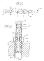
- a preferred embodiment of the apparatus of the present invention is designated generally as 10 in the drawings and is an assembly basically comprised of rigid support structure 12 , a pair of hydraulically-actuated clamp subassemblies 14 and 16 supported by structure 12 , and a hydraulically-actuated tube slitter subassembly 18 also supported by structure 12 .
- subassembly 18 actually functions to form an compression gap throughout the length of the boiler tube end that is to be removed.
- Apparatus assembly 10 is illustrated in Figure 1 as co-operating with the cut-off ends 20 through 26 of boiler tubes previously installed in boiler header 28 .
- Tube end 24 is the tube element part designated for removal from installation within header 28 , and its removal typically occurs in connection with subsequent replacement with a new full-length boiler tube.
- Support structure 12 of apparatus 10 is basically comprised of a base element 30 , a case element 32 which is connected to base element 30 and which houses the principal cutting tool components of subassembly 18 , and a support arm element 34 which is connected to case element 32 and which supports the electrically-actuated stepper motor element 36 of subassembly 18 .
- Case element 32 also supports the hydraulic actuator 38 included in subassembly 18 to accomplish powered reciprocable movement of cutting tools installed within case element 32 .
- the apparatus 10 system also includes sources of pressurized hydraulic fluid and electrical energy (not illustrated), a conventional selectively-operated controller sub-assembly 40 which controls the actuation of subassemblies 14 , 16 , and 18 through conventional hydraulic control valves 42 , and of stepper motor 36 .
- Figure 2 details the elongated slots 44 provided in structure base element 30 to permit lateral adjustments to the positions of hydraulic clamp subassemblies 14 and 16 and thereby facilitate their proper alignment for insertion in respective tube ends 20 and 26 .
- Each clamp subassembly 14 and 16 includes, in addition to disclosed expandable clamping mandrel element 46, a tapered expander element 48 that co-operates with a conical recess in mandrel element 46 and that is connected by a rigid rod 50 to a piston element 52 positioned within a subassembly hydraulic actuator 54 .
- Pressurized hydraulic fluid is flowed into (and from) the interior of hydraulic actuator 54 , usually at a fluid pressures of approximately 2,000 psi, through a supply port referenced as 56 .
- controller 40 When controller 40 operates to open particular control valves 42 to flow pressurized hydraulic fluid to clamping cylinder subassemblies 14 and 16 , such flow causes piston element 52 , connecting rod element 50 , and attached tapered expander element 48 to move upwardly ( Figure 3) and cause the expansion of mandrel element 46 within tube end 20 .
- expandable mandrel elements 46 are released from substantial frictional engagement with the interior wall surface of tube ends 20 and 26 through the downward movement of piston 52 , rod 50 , and expander 48 to permit withdrawal of apparatus 10 from engagement with header 28 and its included tube ends.
- Spring 57 assists in this downward movement.
- a tension spring component 58 is connected to base element 30 and to expandable mandrel 46 to maintain the components of subassembly 14 as a unit during insertion/removal in boiler header 28 and during lateral movement in co-operating slot element 44 .
- expandable mandrel elements 46 be formed of a dense polyurethane material and that rigid expander element 48 be formed of an aluminum alloy.
- mandrel 46 can be formed of an aluminum alloy and be partially segmented.
- Such subassembly essentially functions in the general manner of a reciprocating, metal-shaving shaper machine tool and includes, in addition to conventional, double-acting hydraulic actuator element 38 , a cutting head designated as 60 .
- Cutting head 60 has a generally cylindrical base element 62 that is both slidably contained within structural case 32 and rigidly connected at one end to the actuator rod component 64 of hydraulic actuator 38 by co-operating retainer fitting 66 .
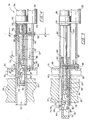
- Figure 4 illustrates the position of cutting head 60 when rod component 64 of hydraulic actuator 38 is fully retracted.
- Figure 5 illustrates the position of cutting head 60 when rod 64 is fully extended.
- Figures 4 and 5 respectively illustrate a subassembly tool holder 68 in its extreme retracted and projected positions before commencing and after completing the cutting of a compression gap in tube end 24 .
- Cutting head 60 also includes a generally tubular drawbar sleeve element 70 that is rigidly secured to the end of base element 62 opposite retainer fitting 66 .
- Drawbar sleeve 70 has an upper surface opening 72 through which toolholder 68 and its included pair of cutting tool bits 74 and 76 (see Figure 8) may be advanced into or withdrawn from contact with wall-thickness metal of tube end 24 .
- Toolholder 68 has an inclined under surface 78 that co-operates with the inclined ramp surface 80 of height-adjustment wedge 82 for vertical support, and a contact face 83 that engages an aft face of opening 72 in drawbar sleeve 70 .
- actuator rod 64 When actuator rod 64 is retracted during a metal-removal stroke, the force required to consequently move engaged cutting tool bits 74 and 76 along their metal-cutting path is transmitted to the tool bits from rod 64 and through retainer fitting 66 , slitter head base element 62 , attached drawbar sleeve 70 , co-operating toolholder face 84 , and toolholder 68 .
- Such drive drain includes, in part and in addition to height-adjustment wedge 82 which has support wheels 84 and an integral hook 86 , an internally-threaded thimble 88 having an integral hook element 90 that engages the integral hook element 86 of wheeled wedge element 82 , and an adjustment shaft 92 that is rotatably supported within base element 62 and that has a threaded end 94 that co-operates with the internal thread of thimble element 88 .
- a toothed sprocket 96 preferably formed integral with the end of adjustment shaft 92 opposite threaded end 94 , journaled drive shaft 97 connected to stepper motor 36 , a toothed sprocket 98 carried by drive shaft 96 , and an endless chain element 100 which connects sprockets 96 and 98 .
- a toothed sprocket 96 preferably formed integral with the end of adjustment shaft 92 opposite threaded end 94 , journaled drive shaft 97 connected to stepper motor 36 , a toothed sprocket 98 carried by drive shaft 96 , and an endless chain element 100 which connects sprockets 96 and 98 .
- three meshing gears 101 , 102 and 103 shown in Figure 9 could be substituted for the sprocket and chain drive unit 96 , 98 , 100 .
- adjustment shaft 92 can rotate relative to its journal support in base element 62 , co-operating threaded thimble 88 is prevented from rotating with it by the rotational restraint of wheeled wedge 82 in a bottom-opening slot 102 provided in the lower face of drawbar sleeve element 70 (see Figure 8) and the interlocking arrangement of wedge hook 86 and thimble hook 90 .
- structure case section 32 is provided with a bottom-opening slot 104 (see Figure 6) to facilitate the longitudinal movement of chain 100 as actuator rod 64 is extended and retracted and consequently moves adjustment shaft 92 , sprockets 96 and 98 , and endless chain 100 with it.
- the support wheels 84 of wheeled wedge element 82 ride on the inner wall surface of boiler tube end 24 as shown in Figures 4 and 5.
- Figure 8 discloses the spaced-apart positioning of tool bits 74 and 76 in their toolholder 68 installation.
- the reciprocating toolholder and tool bits upon completion of the longitudinal cuts, have actually formed a longitudinal gap in the retained boiler tube end that is approximately three-fourths inch wide.
- Such in effect causes formation of a compression gap in the tube wall that has a larger cross-section than the cross-sectional area of the metal actually removed from the tube end by the cutting action of the tool bits.
- the tube slitter assembly 18 also would function if the toolholder had only one bit. If this were the case the assembly would have to be rotated with respect to a tube to make two parallel slots sequentially.
- Boiler tubes to which the present invention has had widest application generally are in the size range of from 2 inches diameter to 4 inches diameter, and with wall thicknesses ranging approximately from 0.095 to 0.180 inches.
- An operating hydraulic pressure of approximately 2,000 pounds per square inch has proven satisfactory with a cutting head reciprocating frequency of 60 cycles per minute being utilized. (Actuator strokes typically may range to approximately 7-8 inches).
- the pulsed actuation of the apparatus stepper motor to reposition a 30° inclined ramp surface provided in the apparatus wheeled wedge element has been controlled to move the toolholder and included tool bits radially toward tube end wall metal in increments of 0.006 inches per completed cutting stroke (per cycle).
- each boiler tube to be removed adjacent the boiler headers in which it has been installed and the severed tube length removed.
- the apparatus of the present invention is located in a manner whereby the tube slitter subassembly 18 is aligned with a tube end of the severed boiler tube and with the apparatus clamp subassemblies 14 and 16 properly inserted in adjacent installed tube ends. Pressurized hydraulic fluid is next ported to the clamp assembly actuators to firmly anchor the invention apparatus in place for forming a compression gap in the wall of the retained tube end using the apparatus tube slitter subassembly 18 .
- pressurized hydraulic fluid is ported to and from the tube slitter subassembly hydraulic actuator to extend the cutter head and included toolholder and tool bits into the length of the retained tube end.
- the apparatus stepper motor is actuated to advance the included toolholder and tool bits radially relative to the tube to a desired cutting depth.
- pressurized hydraulic fluid is ported to and from the tube slitter subassembly hydraulic actuator to retract the cutter head and included toolholder and tool bits from the length of the retained tube end to cause two parallel longitudinally extending slots to be formed in the tube wall.
- the apparatus stepper motor is actuated to retract the included toolholder and tool bits radially relative to the tube in preparation for the next cutting cycle. This causes a remaining strip of metal to be defined between the parallel pair of slots which enables the strip to be removed and which when removed together with said slots defines a compression gap.
- the retained boiler tube end is compressed to substantially close the so-formed compression gap whereby the compressed tube end has a significantly reduced cross-sectional circumference and may be readily withdrawn from retention in the co-operating the boiler header.
Landscapes
- Engineering & Computer Science (AREA)
- Mechanical Engineering (AREA)
- Physics & Mathematics (AREA)
- Thermal Sciences (AREA)
- General Engineering & Computer Science (AREA)
- Drilling And Boring (AREA)
- Automatic Assembly (AREA)
- Milling Processes (AREA)
- Jigs For Machine Tools (AREA)
Applications Claiming Priority (2)
| Application Number | Priority Date | Filing Date | Title |
|---|---|---|---|
| US814093 | 1997-03-10 | ||
| US08/814,093 US5826334A (en) | 1997-03-10 | 1997-03-10 | Boiler tube removal method |
Publications (2)
| Publication Number | Publication Date |
|---|---|
| EP0864810A2 true EP0864810A2 (de) | 1998-09-16 |
| EP0864810A3 EP0864810A3 (de) | 2001-09-12 |
Family
ID=25214152
Family Applications (1)
| Application Number | Title | Priority Date | Filing Date |
|---|---|---|---|
| EP98630006A Withdrawn EP0864810A3 (de) | 1997-03-10 | 1998-02-27 | Methode und Vorrichtung zum Entfernen eines Kesselrohres |
Country Status (3)
| Country | Link |
|---|---|
| US (2) | US5826334A (de) |
| EP (1) | EP0864810A3 (de) |
| CA (1) | CA2230594C (de) |
Cited By (4)
| Publication number | Priority date | Publication date | Assignee | Title |
|---|---|---|---|---|
| EP1092923A3 (de) * | 1999-10-12 | 2001-09-12 | Advanced Cutting Technologies, Ltd. | Vorrichtung zum Scheren und Biegen eines Kesselrohrsegmentes |
| EP1092922A3 (de) * | 1999-10-12 | 2001-09-12 | Advanced Cutting Technologies, Ltd. | Vorrichtung zur Kompression eines aufgeweiteten Kesselrohrendes |
| EP0903537A3 (de) * | 1997-09-22 | 2002-02-27 | Bruce V. Weeks | Methode und Vorrichtung zum Entfernen eines Kesselrohres |
| CN109623333A (zh) * | 2018-12-27 | 2019-04-16 | 南京高速齿轮制造有限公司 | 针对大型齿轮在大过盈量大锥度配合下反复装拆卸的工装及其应用 |
Families Citing this family (19)
| Publication number | Priority date | Publication date | Assignee | Title |
|---|---|---|---|---|
| US6209181B1 (en) * | 1999-10-12 | 2001-04-03 | Advanced Cutting Technologies, Ltd. | Boiler tube flare-end segment peeler tool |
| CA2392648A1 (en) * | 2000-02-01 | 2001-08-09 | Robert Kubsik | Method and apparatus for removing thimbles from the stubs of an anode |
| US7093360B1 (en) | 2004-04-06 | 2006-08-22 | Craig Merrill C | Method of removing boiler tubes |
| US7305756B2 (en) * | 2004-04-22 | 2007-12-11 | Barcock & Wilcox Canada Ltd. | Tube extracting device |
| US7194800B2 (en) * | 2004-06-07 | 2007-03-27 | Babcick & Wilcox Canada, Ltd. | Internal tube extracting device with a cylindrical collapsing wedge |
| US7146716B2 (en) * | 2004-06-08 | 2006-12-12 | Babcock & Wilcox Canada Ltd. | External tube extraction device with a cylindrical collapsing wedge |
| US7168143B2 (en) * | 2004-06-30 | 2007-01-30 | Babcock & Wilcox Canada Ltd. | External tube deforming extraction device |
| US7322090B2 (en) * | 2005-01-19 | 2008-01-29 | Babcock & Wilcox Canada Ltd. | Explosive tube removal device |
| US7657985B2 (en) * | 2006-03-08 | 2010-02-09 | Mcclure Mark W | Modified boiler wall tube tool |
| US8348253B2 (en) * | 2006-03-08 | 2013-01-08 | Mcclure Mark W | Modified boiler wall tube tool |
| US20070296133A1 (en) * | 2006-06-21 | 2007-12-27 | Mcclure Mark W | Modified Boiler Wall Tube Tool Having Inhibiting Means |
| US8104387B2 (en) * | 2006-08-11 | 2012-01-31 | Alstom Technology Ltd | Tube stub removal apparatus |
| US7905686B2 (en) * | 2007-07-02 | 2011-03-15 | Esco Technologies, Inc. | System for removing boiler tube stubs |
| US7950313B2 (en) * | 2007-07-02 | 2011-05-31 | Esco Technologies, Inc. | Method and apparatus for removing boiler tube stubs |
| FR2919917B1 (fr) * | 2007-08-07 | 2009-10-30 | Areva Np Sas | Procede de realisation d'orifices dans les enveloppes secondaires d'un generateur de vapeur d'un reacteur nucleaire a eau sous pression |
| US9656841B2 (en) * | 2014-10-06 | 2017-05-23 | Phil Madron | Fire tube implement, system, and method |
| US11118780B2 (en) | 2015-11-05 | 2021-09-14 | Charger Energy Services, Llc | System and method for removing and replacing fire-tubes |
| US10393368B2 (en) | 2016-12-05 | 2019-08-27 | Scott L. Smith | Saw blade positioning device |
| US20230084823A1 (en) * | 2021-09-14 | 2023-03-16 | Charger Energy Services, Llc | System and method for removing and replacing fire-tubes |
Family Cites Families (19)
| Publication number | Priority date | Publication date | Assignee | Title |
|---|---|---|---|---|
| US408162A (en) * | 1889-07-30 | condon | ||
| GB579756A (en) * | 1945-01-12 | 1946-08-14 | Griscom Russell Co | Method of removing defective tubes from tube sheets |
| US2507201A (en) * | 1946-09-17 | 1950-05-09 | Evans Clair Otto | Tool for removing tubes from tube sheets |
| US3628246A (en) * | 1968-09-06 | 1971-12-21 | Carrier Corp | Apparatus for tube removal |
| US4180903A (en) * | 1978-03-02 | 1980-01-01 | Hannigan Joseph Jr | Apparatus for collapsing steam tubes for removal from a steam boiler |
| US4233730A (en) * | 1978-07-31 | 1980-11-18 | Godbe James R | Boiler tube pulling method and apparatus |
| US4471516A (en) * | 1978-07-31 | 1984-09-18 | Godbe James R | Boiler tube pulling method and apparatus |
| GB8404922D0 (en) * | 1984-02-24 | 1984-03-28 | Babcock Power Ltd | Tool head |
| US4633555A (en) * | 1985-04-10 | 1987-01-06 | Legge Gerald A | Method for cutting tube-walls |
| US4739688A (en) * | 1986-10-07 | 1988-04-26 | Sma Controls, Inc. | Boiler repair |
| US5044075A (en) * | 1986-10-07 | 1991-09-03 | Sma Controls, Inc. | Boiler repair |
| US4830551A (en) * | 1986-10-07 | 1989-05-16 | Sma Controls, Inc. | Boiler repair |
| US4967468A (en) * | 1986-10-27 | 1990-11-06 | Torque And Tension Equipment Inc. | Apparatus for fixing boiler tubes during replacement of same |
| US4872249A (en) * | 1988-07-28 | 1989-10-10 | Tri Tool Inc. | Tool support and guide system for repair of boiler tube panels and process for carrying out repair using same |
| US4979294A (en) * | 1989-07-17 | 1990-12-25 | The Dayton Power & Light Company | Boiler tube repair method |
| US5033347A (en) * | 1989-08-25 | 1991-07-23 | Hillestad Tollief O | Boiler tube cutting apparatus |
| FR2666879B1 (fr) * | 1990-09-19 | 1993-03-19 | Framatome Sa | Procede de remplacement d'un tube d'un echangeur de chaleur a tubes droits et utilisation de ce procede. |
| US5893209A (en) * | 1997-09-22 | 1999-04-13 | Weeks; Bruce V. | Apparatus for effecting boiler tube removal |
| EP1096199A2 (de) * | 1999-10-27 | 2001-05-02 | Advanced Cutting Technologies, Ltd. | Methode zum Entfernen eines Kesselrohres |
-
1997
- 1997-03-10 US US08/814,093 patent/US5826334A/en not_active Expired - Fee Related
-
1998
- 1998-02-26 CA CA002230594A patent/CA2230594C/en not_active Expired - Fee Related
- 1998-02-27 EP EP98630006A patent/EP0864810A3/de not_active Withdrawn
- 1998-06-09 US US09/094,120 patent/US5974642A/en not_active Expired - Fee Related
Cited By (5)
| Publication number | Priority date | Publication date | Assignee | Title |
|---|---|---|---|---|
| EP0903537A3 (de) * | 1997-09-22 | 2002-02-27 | Bruce V. Weeks | Methode und Vorrichtung zum Entfernen eines Kesselrohres |
| EP1092923A3 (de) * | 1999-10-12 | 2001-09-12 | Advanced Cutting Technologies, Ltd. | Vorrichtung zum Scheren und Biegen eines Kesselrohrsegmentes |
| EP1092922A3 (de) * | 1999-10-12 | 2001-09-12 | Advanced Cutting Technologies, Ltd. | Vorrichtung zur Kompression eines aufgeweiteten Kesselrohrendes |
| CN109623333A (zh) * | 2018-12-27 | 2019-04-16 | 南京高速齿轮制造有限公司 | 针对大型齿轮在大过盈量大锥度配合下反复装拆卸的工装及其应用 |
| CN109623333B (zh) * | 2018-12-27 | 2023-08-29 | 南京高速齿轮制造有限公司 | 针对大型齿轮反复装拆的工装及其使用方法 |
Also Published As
| Publication number | Publication date |
|---|---|
| CA2230594C (en) | 2003-01-07 |
| CA2230594A1 (en) | 1998-09-10 |
| US5974642A (en) | 1999-11-02 |
| US5826334A (en) | 1998-10-27 |
| EP0864810A3 (de) | 2001-09-12 |
Similar Documents
| Publication | Publication Date | Title |
|---|---|---|
| CA2230594C (en) | Boiler tube removal method and apparatus | |
| US4752159A (en) | Tapered thread forming apparatus and method | |
| CA1036485A (en) | Tubing cutting apparatus | |
| JP2753125B2 (ja) | チューブ膨張を行う方法および装置 | |
| CA2247488C (en) | Method and apparatus for effecting boiler tube removal | |
| US4289430A (en) | Method and apparatus for simultaneously boring and turning upset pipe end | |
| US3648500A (en) | Method and apparatus for forming cylindrical shapes | |
| GB2069910A (en) | Work clamping apparatus | |
| CN105127501A (zh) | 用于薄壁管件的自动旋切装置及采用其进行旋切的方法 | |
| US4744277A (en) | Method and device for cutting pipe lengths | |
| US20050028658A1 (en) | Apparatus and method for slotting a pipe | |
| US3987523A (en) | Apparatus and method for forming end surfaces on annular work pieces | |
| US6309145B1 (en) | Portable machine tool for conditioning header tube openings for butt-welding tubes | |
| US7223054B1 (en) | Spiral groove pipe joint machining assembly | |
| US2749983A (en) | Pipe and tube cutting apparatus | |
| US7650772B2 (en) | Rotary flaring tool and method of use | |
| US4123189A (en) | Rotary-plunge tube notching system | |
| US20020108478A1 (en) | Apparatus and method for slotting a pipe | |
| US3696481A (en) | Apparatus for performing operations on hydraulic tubing | |
| US20100132520A1 (en) | Method and apparatus for slotting tubular steel | |
| US4345860A (en) | Boring machine and method of rigidizing a boring bar | |
| CN100415424C (zh) | 管内的开槽方法及其应用和用于管内开槽的刀具架 | |
| US3333488A (en) | Annular drilling machine | |
| US4964328A (en) | Notching blade assembly | |
| RU2156675C1 (ru) | Устройство для резки труб |
Legal Events
| Date | Code | Title | Description |
|---|---|---|---|
| PUAI | Public reference made under article 153(3) epc to a published international application that has entered the european phase |
Free format text: ORIGINAL CODE: 0009012 |
|
| AK | Designated contracting states |
Kind code of ref document: A2 Designated state(s): AT BE CH DE DK ES FI FR GB GR IE IT LI LU MC NL PT SE Kind code of ref document: A2 Designated state(s): DE FR GB IT SE |
|
| AX | Request for extension of the european patent |
Free format text: AL;LT;LV;MK;RO;SI |
|
| 17P | Request for examination filed |
Effective date: 19990722 |
|
| PUAL | Search report despatched |
Free format text: ORIGINAL CODE: 0009013 |
|
| AK | Designated contracting states |
Kind code of ref document: A3 Designated state(s): AT BE CH DE DK ES FI FR GB GR IE IT LI LU MC NL PT SE |
|
| AX | Request for extension of the european patent |
Free format text: AL;LT;LV;MK;RO;SI |
|
| RIC1 | Information provided on ipc code assigned before grant |
Free format text: 7F 22B 37/58 A, 7B 23D 21/02 B |
|
| AKX | Designation fees paid |
Free format text: DE FR GB IT SE |
|
| 17Q | First examination report despatched |
Effective date: 20070831 |
|
| STAA | Information on the status of an ep patent application or granted ep patent |
Free format text: STATUS: THE APPLICATION IS DEEMED TO BE WITHDRAWN |
|
| 18D | Application deemed to be withdrawn |
Effective date: 20080111 |