EP0864828A2 - Hubbalkenofen - Google Patents
Hubbalkenofen Download PDFInfo
- Publication number
- EP0864828A2 EP0864828A2 EP98104440A EP98104440A EP0864828A2 EP 0864828 A2 EP0864828 A2 EP 0864828A2 EP 98104440 A EP98104440 A EP 98104440A EP 98104440 A EP98104440 A EP 98104440A EP 0864828 A2 EP0864828 A2 EP 0864828A2
- Authority
- EP
- European Patent Office
- Prior art keywords
- walking beam
- beam furnace
- furnace according
- flat
- supporting webs
- Prior art date
- Legal status (The legal status is an assumption and is not a legal conclusion. Google has not performed a legal analysis and makes no representation as to the accuracy of the status listed.)
- Granted
Links
- 239000000463 material Substances 0.000 claims abstract description 18
- 238000000137 annealing Methods 0.000 claims abstract description 12
- 230000000630 rising effect Effects 0.000 claims description 2
- 238000010438 heat treatment Methods 0.000 description 3
- 239000002826 coolant Substances 0.000 description 1
Images


Classifications
-
- F—MECHANICAL ENGINEERING; LIGHTING; HEATING; WEAPONS; BLASTING
- F27—FURNACES; KILNS; OVENS; RETORTS
- F27B—FURNACES, KILNS, OVENS OR RETORTS IN GENERAL; OPEN SINTERING OR LIKE APPARATUS
- F27B9/00—Furnaces through which the charge is moved mechanically, e.g. of tunnel type; Similar furnaces in which the charge moves by gravity
- F27B9/14—Furnaces through which the charge is moved mechanically, e.g. of tunnel type; Similar furnaces in which the charge moves by gravity characterised by the path of the charge during treatment; characterised by the means by which the charge is moved during treatment
- F27B9/20—Furnaces through which the charge is moved mechanically, e.g. of tunnel type; Similar furnaces in which the charge moves by gravity characterised by the path of the charge during treatment; characterised by the means by which the charge is moved during treatment the charge moving in a substantially straight path
- F27B9/22—Furnaces through which the charge is moved mechanically, e.g. of tunnel type; Similar furnaces in which the charge moves by gravity characterised by the path of the charge during treatment; characterised by the means by which the charge is moved during treatment the charge moving in a substantially straight path on rails, e.g. under the action of scrapers or pushers
-
- F—MECHANICAL ENGINEERING; LIGHTING; HEATING; WEAPONS; BLASTING
- F27—FURNACES; KILNS; OVENS; RETORTS
- F27D—DETAILS OR ACCESSORIES OF FURNACES, KILNS, OVENS OR RETORTS, IN SO FAR AS THEY ARE OF KINDS OCCURRING IN MORE THAN ONE KIND OF FURNACE
- F27D3/00—Charging; Discharging; Manipulation of charge
- F27D3/02—Skids or tracks for heavy objects
Definitions
- annealing material which can be used with both rectangular as well as round cross-section occurs are used as walking beam and pacemaker furnaces, as transporting the annealing material with less damage than ensure, for example, pusher furnaces through which Annealing material is pushed through.
- German published application 39 39 582 is a Walking beam furnace with supporting bars for the annealing material on the coolant-flowed walking and fixed beams known which locking elements received by the supporting webs because of their easy accessibility in simple Have it welded to the beams.
- the embodiment is trough-shaped towards the center lowered. This results in the lowering area Holding jaws as position securing for heat goods with uneven contact surfaces, such as round material.
- German patent application 43 43 675 describes a walking beam furnace, on the respective cooled walking beam and / or fixed beams short fasteners for Support bars running at an angle to the transport direction flat supports for the annealing material are arranged. With With the help of web bolts, these webs can be attached to their End holes or eyelets in one be fixed at the same angle to the longitudinal axis.
- a major disadvantage of the walking beam furnaces described above is that their requirements only are designed for round or flat material.
- the invention is based on the problem a walking beam furnace for heating round and of creating flat material.
- the solution to this problem is a walking beam furnace, on its walking beam and fixed beam different Support bars for round or flat material are arranged.
- the flat goods supporting webs have one in the feed direction wider middle part with a flat surface and each one narrower in the feed direction and sloping slope behind the middle section.
- the round goods support webs are trough-shaped; they are preferably narrow in the middle horizontal surface and two rising to the right and left of it Slants on.
- the width of the round goods support bars in the feed direction, the width of the beveled Parts of the flat goods support webs correspond.
- the slopes the round goods and the slopes of the flat goods supporting webs are matched to each other in such a way that View of a wavy surface of the supporting bars results in the underlying troughs Alternate higher areas.
- the troughs serve to the round annealing material against shifting in to secure its transport position.
- Flat annealing material for example slabs, on the other hand can over the troughs lie on the outstanding, flat surfaces.
- the slopes of the supporting bars also point in Direction of transport seen falling to the right or left Surfaces on. Step on the round-goods supporting bridges this moves on; in the case of the flat goods supporting bars, however with every slope right and left.
- the sloping surfaces reduce the build-up of scale on the supporting bars.
- the lifting and fixed beams can be on their surface have a longitudinal web. This is from includes the U-shaped foot of the supporting webs.
- the Flat goods support webs that have a hole on the side, are attached to the longitudinal web with the help of bolts.
- the Round goods support bars are placed on the longitudinal bar and by positive locking between two flat goods supporting webs fixed positively in their position and thus secured against loosening. This makes it easy Exchanging the round goods carrier bars allows.
- Walking beam and fixed beam 1 consist of a cooled Support tube 2 with flat goods support bars 3 and round goods support bars 4.
- the supporting bars 3 and 4 are in alternating Order arranged on the support tube 2.
- the flat goods supporting webs 3 have a flat contact surface 5 and one each in the feed direction in front and bevel behind it 6.
- the round goods supporting webs 4 are characterized by a - seen from the side - Narrow, horizontal surface in the middle 7 from, in front of and behind in the feed direction lying slopes 8 rise.
- the flat pads 5 serve as a support surface for flat Warm material, while from slopes 6, 8 and horizontal surface 7 existing troughs of the recording serve from round heating material.
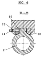
- the flat goods supporting webs 3 there is one in the middle Bore 9 for receiving one of the mounting on the support tube 2 serving bolt 13 against by a stopper 14 Falling out of the bolt 13 is closed.
- the bolt 13 connects the flat goods support web 3 with one on one Longitudinal web 10 welded cams 15, which also has a hole in the middle.
- the round goods supporting webs 4 are only on the longitudinal web 10 of the support tube 2 attached, by positive locking held between two flat goods supporting webs 3 and secured at the same time against lifting off.
- Fig. 3 can be seen that the flat support 5 of the Flat goods support web 3 is wider in the feed direction as its bevels 6 and the round goods-supporting webs 4. The serves to ensure the necessary contact area for the flat annealing material.
- the slopes 6 are seen on the right in the feed direction and bevelled again on the left.
- the slopes 8 the round goods supporting webs 4 have such a bevel 12 only offset. This arrangement reduces scale build-up on the supporting bars. It also causes the arrangement of the cushions and the change of the side sloping slopes a constant change of Supporting the annealing material and thus its uniformity Heat.
Landscapes
- Engineering & Computer Science (AREA)
- Mechanical Engineering (AREA)
- General Engineering & Computer Science (AREA)
- Heat Treatments In General, Especially Conveying And Cooling (AREA)
- Tunnel Furnaces (AREA)
- Reciprocating Conveyors (AREA)
Abstract
Description
- Fig. 1
- eine Draufsicht auf einen Hub- oder Festbalken eines Hubbalkenofens,
- Fig. 2
- eine Seitenansicht des Hub- oder Festbalkens der Fig. 1,
- Fig. 3
- eine Draufsicht auf mehrere Tragstege,
- Fig. 4
- einen Querschnitt entlang der Linie IV - IV gemäß Fig. 2,
- Fig. 5
- einen Querschnitt entlang der Linie V - V gemäß Fig. 2,
- Fig. 6
- einen Querschnitt entlang der Linie VI - VI gemäß Fig. 2.
Claims (17)
- Hubbalkenofen mit Fest- und Hubbalken mitTragstegen (3) für flaches Glühgut undTragstegen (4) für rundes Glühgut.
- Hubbalkenofen nach Anspruch 1, dadurch gekennzeichnet, daß die Hub- und die Festbalken (1) auf ihrer Oberseite einen Längssteg (10) zur Aufnahme der Tragstege aufweisen.
- Hubbalkenofen nach Anspruch 1 oder 2, dadurch gekennzeichnet, daß die Tragstege (3, 4) einen dem Längssteg (10) angepaßten Fuß und eine Auflage (5, 6, 7, 8) besitzen.
- Hubbalkenofen nach einem der Ansprüche 1 bis 3, dadurch gekennzeichnet, daß die Flachgut- und die Rundgut-Tragstege (3, 4) versetzt angeordnet sind.
- Hubbalkenofen nach einem der Ansprüche 1 bis 4, dadurch gekennzeichnet, daß die Flachgut-Tragstege (3) lösbar mit dem Balken (1) verbunden sind.
- Hubbalkenofen nach einem der Ansprüche 1 bis 5, dadurch gekennzeichnet, daß die Flachgut-Tragstege (3) eine flache Auflage (5) und je eine in Vorschubrichtung davor und dahinter liegende abfallende Schräge (6) besitzen.
- Hubbalkenofen nach Anspruch 6, dadurch gekennzeichnet, daß die abfallenden Schrägen (6) in Vorschubrichtung gesehen beidseitig abfallende Flächen (11) aufweisen.
- Hubbalkenofen nach einem der Ansprüche 5 bis 7, dadurch gekennzeichnet, daß die flache Auflage (5) breiter ist als die Rundgut-Auflage (6, 7, 8).
- Hubbalkenofen nach einem der Ansprüche 1 bis 8, dadurch gekennzeichnet, daß die Flachgut-Tragstege (3) seitliche Bohrungen (9) aufweisen.
- Hubbalkenofen nach einem der Ansprüche 1 bis 9, dadurch gekennzeichnet, daß die Rundgut-Tragstege (4) formschlüssig zwischen zwei Flachgut-Tragstegen (3) angeordnet sind.
- Hubbalkenofen nach einem der Ansprüche 1 bis 10, dadurch gekennzeichnet, daß die Auflage der Rundgut-Tragstege (4) aus einem schmalen flachen Teil (7) und je einer in Vorschubrichtung davor und dahinter liegenden ansteigenden Schräge (8) besteht.
- Hubbalkenofen nach Anspruch 10 oder 11, dadurch gekennzeichnet, daß die ansteigenden Schrägen (8) in Vorschubrichtung gesehen jeweils versetzt nach rechts oder links abfallende Flächen (12) aufweisen.
- Hubbalkenofen nach einem der Ansprüche 1 bis 12, dadurch gekennzeichnet, daß der Längssteg (10) Nocken (15) aufweist.
- Hubbalkenofen nach Anspruch 13, dadurch gekennzeichnet, daß die Nocken (15) beidseitig an dem Längssteg angeschweißt sind.
- Hubbalkenofen nach Anspruch 13 oder 14, dadurch gekennzeichnet, daß die Nocken (15) Bohrungen aufweisen.
- Hubbalkenofen nach einem der Ansprüche 1 bis 15, dadurch gekennzeichnet, daß die Flachgut-Tragstege (3) mittels Bolzen (13) mit den Nocken (15) verbunden sind.
- Hubbalkenofen nach Anspruch 16, dadurch gekennzeichnet, daß die Bolzen (13) durch Stopfen (14) gegen ein Herausfallen gesichert sind.
Applications Claiming Priority (2)
| Application Number | Priority Date | Filing Date | Title |
|---|---|---|---|
| DE19710870 | 1997-03-15 | ||
| DE19710870A DE19710870A1 (de) | 1997-03-15 | 1997-03-15 | Hubbalkenofen |
Publications (3)
| Publication Number | Publication Date |
|---|---|
| EP0864828A2 true EP0864828A2 (de) | 1998-09-16 |
| EP0864828A3 EP0864828A3 (de) | 1999-12-15 |
| EP0864828B1 EP0864828B1 (de) | 2004-10-06 |
Family
ID=7823545
Family Applications (1)
| Application Number | Title | Priority Date | Filing Date |
|---|---|---|---|
| EP98104440A Expired - Lifetime EP0864828B1 (de) | 1997-03-15 | 1998-03-12 | Hubbalkenofen |
Country Status (6)
| Country | Link |
|---|---|
| US (1) | US6095804A (de) |
| EP (1) | EP0864828B1 (de) |
| CN (1) | CN1172154C (de) |
| AT (1) | ATE278923T1 (de) |
| CA (1) | CA2232208A1 (de) |
| DE (2) | DE19710870A1 (de) |
Families Citing this family (3)
| Publication number | Priority date | Publication date | Assignee | Title |
|---|---|---|---|---|
| AT409670B (de) * | 2001-01-15 | 2002-10-25 | Hertwich Engineering Gmbh | Hubbalkenförderer für einen durchlaufofen zum erwärmen von aluminiumbarren |
| JP4738372B2 (ja) * | 2007-04-03 | 2011-08-03 | 株式会社ノリタケカンパニーリミテド | ウオーキングビーム式熱処理装置 |
| DE102018129446B4 (de) * | 2018-11-22 | 2024-03-14 | Saint-Gobain Industriekeramik Rödental GmbH | Balken für Balkenförderofen |
Family Cites Families (12)
| Publication number | Priority date | Publication date | Assignee | Title |
|---|---|---|---|---|
| US1361254A (en) * | 1919-06-19 | 1920-12-07 | Wickwire Spencer Steel Corp | Ingot-skid for ingot-heating furnaces |
| US2983498A (en) * | 1958-10-09 | 1961-05-09 | Macgregor Brothers | Conveying apparatus |
| DE2143214C2 (de) * | 1971-08-28 | 1974-01-24 | August Thyssen-Huette Ag, 4100 Duisburghamborn | Selbsttragende Gleitschiene eines Stoßofens mit aufgesetzten Reitern |
| JPS5154813A (en) * | 1974-11-08 | 1976-05-14 | Chugai Ro Kogyo Kaisha Ltd | Marukohenkanetsuro |
| JPS5355876A (en) * | 1976-10-30 | 1978-05-20 | Yoshida Kogyo Kk | Intermittent feeder of portion material |
| US4391587A (en) * | 1980-03-27 | 1983-07-05 | Nippon Steel Corporation | Slab heating furnace |
| DE8901064U1 (de) * | 1989-02-01 | 1989-04-20 | Reining Heisskühlung GmbH & Co. KG, 4330 Mülheim | Aufsatzstück für kühlmitteldurchströmte Tragrohre in Wärmeöfen, insbesondere Hubbalkenöfen |
| DE4002870A1 (de) * | 1990-02-01 | 1991-08-08 | Loi Ind Ofenanlagen | Vorrichtung zum abstuetzen von waermebehandlungsgut in einem erwaermungsofen |
| DE4203595C2 (de) * | 1992-02-10 | 2001-07-19 | Loi Thermprocess Gmbh | Vorrichtung zum Abstützen von Einsatzgut in einem Erwärmungsofen |
| US5405264A (en) * | 1992-04-23 | 1995-04-11 | Loi Essen Industrieofenanlagen Gmbh | Device for carrying a charge in a furnace |
| US5334014A (en) * | 1993-03-30 | 1994-08-02 | Btu International | Walking beam furnace |
| DE4343675A1 (de) * | 1993-12-21 | 1995-06-22 | Italimpianti Deutschland Gmbh | Hubbalkenofen |
-
1997
- 1997-03-15 DE DE19710870A patent/DE19710870A1/de not_active Withdrawn
-
1998
- 1998-03-12 US US09/041,267 patent/US6095804A/en not_active Expired - Lifetime
- 1998-03-12 EP EP98104440A patent/EP0864828B1/de not_active Expired - Lifetime
- 1998-03-12 DE DE59812054T patent/DE59812054D1/de not_active Expired - Lifetime
- 1998-03-12 AT AT98104440T patent/ATE278923T1/de active
- 1998-03-13 CN CNB981096875A patent/CN1172154C/zh not_active Expired - Fee Related
- 1998-03-16 CA CA002232208A patent/CA2232208A1/en not_active Abandoned
Also Published As
| Publication number | Publication date |
|---|---|
| EP0864828B1 (de) | 2004-10-06 |
| CN1202613A (zh) | 1998-12-23 |
| ATE278923T1 (de) | 2004-10-15 |
| DE59812054D1 (de) | 2004-11-11 |
| DE19710870A1 (de) | 1998-09-17 |
| CN1172154C (zh) | 2004-10-20 |
| US6095804A (en) | 2000-08-01 |
| CA2232208A1 (en) | 1998-09-15 |
| EP0864828A3 (de) | 1999-12-15 |
Similar Documents
| Publication | Publication Date | Title |
|---|---|---|
| EP1585862B1 (de) | Spindelvorrichtung zur höhenverstellung von gleisrosten | |
| DE2715717C3 (de) | Ankerschiene mit Schienenhalterung für ein Magnetschwebefahrzeug | |
| HUE027845T2 (en) | Tool for fixing rail tracks | |
| DE10200175A1 (de) | Raupenfahrwerk | |
| DE69120093T2 (de) | Brückenelement | |
| EP0090986A2 (de) | Fugenüberbrückungsvorrichtung für Dehnfugen in Fahrbahnen von Brücken oder dergleichen | |
| EP0864828B1 (de) | Hubbalkenofen | |
| DE19633082C2 (de) | Vorrichtung zum lösbaren Befestigen von Leitungen | |
| EP3552931A1 (de) | Steighilfe | |
| CH686618A5 (de) | Gradfuhrung fur Transportschlitten. | |
| DE29711498U1 (de) | Hubbalkenofen | |
| CH640759A5 (de) | Drehmaschine. | |
| DE3909797C1 (en) | Energy supply chain for receiving cables and/or lines | |
| DE7701673U1 (de) | Bolzenschneider | |
| EP0616080B1 (de) | Tragplatte für Brücken und Rampen | |
| WO2000025994A1 (de) | Schneideinrichtung zum längsteilen von materialbahnen mit lösbarem messerkopf | |
| DE4042215A1 (de) | Fahrdrahtkreuzung fuer elektrofahrzeuge mit stromabnehmerbuegel | |
| DE3831804A1 (de) | Vorrichtung zum montieren von zusatzeinrichtungen | |
| DE19851704A1 (de) | Fahrzeugsystem zum Gütertransport | |
| EP0660061B1 (de) | Hubbalkenofen | |
| DE2856180C2 (de) | Zerlegbare Brücke mit Unterspannung | |
| DE3414304A1 (de) | Strebausbaugestell | |
| DE3407960A1 (de) | Aufhaengung fuer eine kranbahn | |
| EP0194283A1 (de) | Tragsystem und reiter zum abstützen von wärmgut | |
| DE3820884C2 (de) |
Legal Events
| Date | Code | Title | Description |
|---|---|---|---|
| PUAI | Public reference made under article 153(3) epc to a published international application that has entered the european phase |
Free format text: ORIGINAL CODE: 0009012 |
|
| AK | Designated contracting states |
Kind code of ref document: A2 Designated state(s): AT DE FR IT |
|
| AX | Request for extension of the european patent |
Free format text: AL;LT;LV;MK;RO;SI |
|
| PUAL | Search report despatched |
Free format text: ORIGINAL CODE: 0009013 |
|
| AK | Designated contracting states |
Kind code of ref document: A3 Designated state(s): AT BE CH DE DK ES FI FR GB GR IE IT LI LU MC NL PT SE |
|
| AX | Request for extension of the european patent |
Free format text: AL;LT;LV;MK;RO;SI |
|
| RTI1 | Title (correction) |
Free format text: WALKING BEAM FURNACE |
|
| 17P | Request for examination filed |
Effective date: 20000615 |
|
| AKX | Designation fees paid |
Free format text: AT DE FR IT |
|
| GRAP | Despatch of communication of intention to grant a patent |
Free format text: ORIGINAL CODE: EPIDOSNIGR1 |
|
| GRAS | Grant fee paid |
Free format text: ORIGINAL CODE: EPIDOSNIGR3 |
|
| GRAA | (expected) grant |
Free format text: ORIGINAL CODE: 0009210 |
|
| AK | Designated contracting states |
Kind code of ref document: B1 Designated state(s): AT DE FR IT |
|
| REF | Corresponds to: |
Ref document number: 59812054 Country of ref document: DE Date of ref document: 20041111 Kind code of ref document: P |
|
| RAP2 | Party data changed (patent owner data changed or rights of a patent transferred) |
Owner name: TECHINT COMPAGNIA TECNICA INTERNAZIONALE S.P.A. |
|
| PLBE | No opposition filed within time limit |
Free format text: ORIGINAL CODE: 0009261 |
|
| STAA | Information on the status of an ep patent application or granted ep patent |
Free format text: STATUS: NO OPPOSITION FILED WITHIN TIME LIMIT |
|
| ET | Fr: translation filed | ||
| 26N | No opposition filed |
Effective date: 20050707 |
|
| REG | Reference to a national code |
Ref country code: FR Ref legal event code: CA |
|
| PGFP | Annual fee paid to national office [announced via postgrant information from national office to epo] |
Ref country code: AT Payment date: 20140226 Year of fee payment: 17 Ref country code: FR Payment date: 20140311 Year of fee payment: 17 |
|
| PGFP | Annual fee paid to national office [announced via postgrant information from national office to epo] |
Ref country code: DE Payment date: 20140417 Year of fee payment: 17 |
|
| REG | Reference to a national code |
Ref country code: DE Ref legal event code: R119 Ref document number: 59812054 Country of ref document: DE |
|
| REG | Reference to a national code |
Ref country code: AT Ref legal event code: MM01 Ref document number: 278923 Country of ref document: AT Kind code of ref document: T Effective date: 20150312 |
|
| REG | Reference to a national code |
Ref country code: FR Ref legal event code: ST Effective date: 20151130 |
|
| PG25 | Lapsed in a contracting state [announced via postgrant information from national office to epo] |
Ref country code: DE Free format text: LAPSE BECAUSE OF NON-PAYMENT OF DUE FEES Effective date: 20151001 |
|
| PG25 | Lapsed in a contracting state [announced via postgrant information from national office to epo] |
Ref country code: FR Free format text: LAPSE BECAUSE OF NON-PAYMENT OF DUE FEES Effective date: 20150331 Ref country code: AT Free format text: LAPSE BECAUSE OF NON-PAYMENT OF DUE FEES Effective date: 20150312 |
|
| PGFP | Annual fee paid to national office [announced via postgrant information from national office to epo] |
Ref country code: IT Payment date: 20170228 Year of fee payment: 20 |