EP0864861A1 - Messanordnung zur Untersuchung gasförmiger Medien - Google Patents
Messanordnung zur Untersuchung gasförmiger Medien Download PDFInfo
- Publication number
- EP0864861A1 EP0864861A1 EP98103004A EP98103004A EP0864861A1 EP 0864861 A1 EP0864861 A1 EP 0864861A1 EP 98103004 A EP98103004 A EP 98103004A EP 98103004 A EP98103004 A EP 98103004A EP 0864861 A1 EP0864861 A1 EP 0864861A1
- Authority
- EP
- European Patent Office
- Prior art keywords
- gas
- measuring arrangement
- arrangement according
- sensor
- sensor element
- Prior art date
- Legal status (The legal status is an assumption and is not a legal conclusion. Google has not performed a legal analysis and makes no representation as to the accuracy of the status listed.)
- Granted
Links
- 238000005259 measurement Methods 0.000 title description 6
- 239000000203 mixture Substances 0.000 claims abstract description 4
- 239000012528 membrane Substances 0.000 claims description 21
- 238000009792 diffusion process Methods 0.000 claims description 19
- 238000013016 damping Methods 0.000 claims description 17
- 230000004888 barrier function Effects 0.000 claims description 11
- 238000002347 injection Methods 0.000 claims description 3
- 239000007924 injection Substances 0.000 claims description 3
- 230000007704 transition Effects 0.000 claims description 2
- 238000011835 investigation Methods 0.000 claims 1
- 230000006872 improvement Effects 0.000 abstract description 2
- 230000004044 response Effects 0.000 abstract description 2
- 239000007789 gas Substances 0.000 description 39
- 210000002445 nipple Anatomy 0.000 description 9
- 230000007246 mechanism Effects 0.000 description 4
- 238000004868 gas analysis Methods 0.000 description 3
- 230000010349 pulsation Effects 0.000 description 3
- 230000009467 reduction Effects 0.000 description 3
- UGFAIRIUMAVXCW-UHFFFAOYSA-N Carbon monoxide Chemical compound [O+]#[C-] UGFAIRIUMAVXCW-UHFFFAOYSA-N 0.000 description 2
- 238000010276 construction Methods 0.000 description 2
- 230000000694 effects Effects 0.000 description 2
- 238000011156 evaluation Methods 0.000 description 2
- 239000003546 flue gas Substances 0.000 description 2
- 238000010438 heat treatment Methods 0.000 description 2
- 230000035945 sensitivity Effects 0.000 description 2
- -1 B. CO Chemical compound 0.000 description 1
- 238000004458 analytical method Methods 0.000 description 1
- QVGXLLKOCUKJST-UHFFFAOYSA-N atomic oxygen Chemical compound [O] QVGXLLKOCUKJST-UHFFFAOYSA-N 0.000 description 1
- 238000006243 chemical reaction Methods 0.000 description 1
- 238000002485 combustion reaction Methods 0.000 description 1
- 230000000052 comparative effect Effects 0.000 description 1
- 238000013461 design Methods 0.000 description 1
- 238000001514 detection method Methods 0.000 description 1
- 230000007613 environmental effect Effects 0.000 description 1
- 230000002349 favourable effect Effects 0.000 description 1
- 230000006870 function Effects 0.000 description 1
- 230000007274 generation of a signal involved in cell-cell signaling Effects 0.000 description 1
- 238000001746 injection moulding Methods 0.000 description 1
- 238000004519 manufacturing process Methods 0.000 description 1
- 238000000465 moulding Methods 0.000 description 1
- 238000005457 optimization Methods 0.000 description 1
- 239000001301 oxygen Substances 0.000 description 1
- 229910052760 oxygen Inorganic materials 0.000 description 1
- 238000012545 processing Methods 0.000 description 1
- 230000033764 rhythmic process Effects 0.000 description 1
- 239000000243 solution Substances 0.000 description 1
- 239000000126 substance Substances 0.000 description 1
- 238000012360 testing method Methods 0.000 description 1
- 239000002341 toxic gas Substances 0.000 description 1
- 230000007723 transport mechanism Effects 0.000 description 1
- 238000011144 upstream manufacturing Methods 0.000 description 1
Images

Classifications
-
- G—PHYSICS
- G01—MEASURING; TESTING
- G01N—INVESTIGATING OR ANALYSING MATERIALS BY DETERMINING THEIR CHEMICAL OR PHYSICAL PROPERTIES
- G01N33/00—Investigating or analysing materials by specific methods not covered by groups G01N1/00 - G01N31/00
- G01N33/0004—Gaseous mixtures, e.g. polluted air
- G01N33/0009—General constructional details of gas analysers, e.g. portable test equipment
- G01N33/0011—Sample conditioning
- G01N33/0016—Sample conditioning by regulating a physical variable, e.g. pressure or temperature
Definitions
- the invention relates to a measuring arrangement for examination gaseous media according to the preamble of claim 1.
- Electrochemical gas sensors used for detection and measurement the concentration of oxygen or toxic gases e.g. B. CO, NO, NO2, SO2, are considered to be commercially available Components have long been known and for example in the DE 44 17 665 A1 described as part of a measuring arrangement, from which the invention is based.
- the measuring arrangement consists of a sensor element, which electrical signals according to the concentration and / or the composition of the gas generated.
- the gas becomes the sensor element fed via a gas supply element and from derived this via a gas discharge element.
- the gas to be detected and get into the sensor two transport mechanisms are closed differentiate.
- part of this gas is transferred a diffusion process into the interior of the sensor element, and is used for signal generation.
- the diffusion takes place due to a gas concentration gradient towards a working electrode located inside the Sensor is located.
- the working electrode sets the gas in one chemical reaction and acts like a sink.
- the gas to be analyzed must use a Transport device, for example the one mentioned Pump to be conveyed to the sensor before it reaches the sensor element are supplied via the described diffusion mechanisms can.
- the problem in this context is that of transport of the gas to be analyzed pumps, such as membrane pumps, used, the pressure surges in the funded Generate gas flow.
- the diffusion mechanism is caused by these pressure surges sensitively disturbed because of the pressure surges resulting convection or concentration fluctuations Mass flows of gas lead, which are related to the Overlay the diffusion process.
- the measurement result as a result of a greatly inflated or uncontrolled fluctuating sensor signal falsified.
- the Sensor element is a more or less pronounced Determine pressure surge sensitivity.
- the invention was therefore based on the problem of a measuring arrangement to further develop the type described at the beginning, that it no longer has the disadvantages described. Especially a measuring arrangement should be created which at small space requirement and inexpensive sufficient damping effect achieved in particular the use of electrochemical Gas sensors in small gas analyzers too enable.
- the invention is based on the idea of the damping element in to integrate the sensor housing and thus an extremely compact Realizing the construction.
- the damping element is therefore an integral part of this assembly, without the need for further, separate damping elements.
- the damping element is preferably designed as an expansion chamber, so that pressure surges are reduced without further measures will.
- the expansion chamber is a particularly simple concept to be molded into a housing cover, which on the Sensor element receiving lower housing part is placed. Furthermore, the housing cover carries the gas supply element and the gas discharge element, for example as a hose nipple are trained.
- the housing cover can be used as an injection molded part inexpensive to manufacture and also allows easy access to the sensor element.
- a particularly low signal distortion can then be observed if the expansion chamber as a cylindrical recess is formed and the gas supply element and the gas discharge element radially and opposite each other into the expansion chamber flow out.
- the cylindrical design of the expansion chamber allows the realization of a comparative large volume in a small space. It has been shown that Expansion chambers with a volume that is about a third of that The volume of the sensor is sufficient for sufficient damping enough.
- the housing cover has a wall section in the form of an elastically yielding compensation membrane having. Pulsations or pressure surges in the supplied Sample gas flow is through a corresponding elastic compensation of the compensating membrane additionally compensated, so that there is an almost complete reduction in pressure surges can be achieved.
- the volume of the expansion chamber can also be adjusted reduce because the compensating membrane is part of the Damping function takes over.
- the compensating membrane is preferably in one piece with the housing cover injection molded so that they are comparatively small Effort can be realized.
- a diffusion barrier in the form of a disk is provided, the on the housing cover in the area of the transition from the Expansion chamber is attached to the sensor element.
- the disc has axial through holes of small diameter, the act as capillaries. They act as another Attenuator for those already weakened in the expansion chamber Pressure surges.
- Diffusion barriers can be attached to a diffusion membrane thus the interface between the actual sensor element and the damping arrangement.
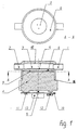
- a well-known and commercially available sensor element 4 is received by a lower housing part 16.
- a housing cover 15 is placed on the Gas supply element in the form of an inlet nipple 1 and a Has gas discharge element in the form of an outlet nipple 2.
- the inlet nipple 1 and the outlet nipple 2 are opposite to each other arranged and each open radially into a cylindrical Recess 3, which is within the housing cover 15 is molded and as an expansion chamber for the by the Inlet nipple 1 supplied, pressure surge gas is used.
- the passage barrier has three axial Through holes 7 of small diameter, which are called capillary holes Act.
- the Passage barrier 6 provided with a membrane 5, at least covers the area of the capillary bores 7 and thus their direct flow prevented.
- a diffusion membrane 8 attached on the opposite Side, i.e. is directed towards the sensor element 4 .
- the measurement signals are in the form of so-called raw signals Pins 9 provided. Usually they get there from there via a line to the evaluation unit, where it is under Consideration of sensor-specific data stored there be evaluated.
- the raw signals however, via the connecting pins 9 to a printed circuit board 10 transferred, with the help of known molded parts 11 attached to the sensor element 4 or to the lower housing part 16 are.
- the circuit board 10 is electrical and electronic Components equipped, among other things an identification of the sensor type and further processing of the sensor signal enable.
- EEPROM integrated electronic Memory chip
- the data relevant to the operation of the sensor for example whose sensitivity contains.
- EEPROM integrated electronic Memory chip
- the variant shown in Figure 2 differs from the previously described in that the housing cover 15 contains a compensating membrane 14. This extends practically completely over the entire end face of the housing cover 15 and is integrally molded in the injection molding process.
- the compensating membrane 14 is thus able to Avoid the rhythm of the pressure surges of the supplied gas flow and thus equalizes pressure fluctuations within the expansion chamber 3 largely from.
- This variant is particularly advantageous if that Volume of the expansion chamber 3 is too small to accommodate the pressure fluctuations dampen the upstream pump sufficiently. It also allows a reduction in the volume of the expansion chamber 3, so that the entire measuring arrangement is smaller overall can be interpreted. This means that such pumps can also be used Use that produce strong pressure surges. Even short ones There are no hose routes between the pump and the gas sensor to impermissible signal distortions.
Landscapes
- Chemical & Material Sciences (AREA)
- Life Sciences & Earth Sciences (AREA)
- Engineering & Computer Science (AREA)
- Health & Medical Sciences (AREA)
- Analytical Chemistry (AREA)
- General Physics & Mathematics (AREA)
- Medicinal Chemistry (AREA)
- Physics & Mathematics (AREA)
- Combustion & Propulsion (AREA)
- Biochemistry (AREA)
- General Health & Medical Sciences (AREA)
- Food Science & Technology (AREA)
- Immunology (AREA)
- Pathology (AREA)
- Measuring Fluid Pressure (AREA)
- Sampling And Sample Adjustment (AREA)
- Investigating Or Analyzing Materials By The Use Of Fluid Adsorption Or Reactions (AREA)
- Investigating Or Analyzing Materials By The Use Of Electric Means (AREA)
- Measuring Oxygen Concentration In Cells (AREA)
Abstract
Description
- Fig. 1
- Meßanordnung,
- Fig. 2
- Meßanordnung, Variante gemäß Fig. 1
- 1
- Einlaßnippel
- 2
- Auslaßnippel
- 3
- Expansionskammer
- 4
- Sensorelement
- 5
- Membran
- 6
- Durchtrittsbarriere
- 7
- Kapillarbohrungen
- 8
- Diffusionsmembran
- 9
- Anschlußstift
- 10
- Leiterplatte
- 11
- Formteil
- 12
- Speicherbaustein
- 13
- Steckverbinder
- 14
- Ausgleichsmembran
- 15
- Gehäusedeckel
- 16
- Gehäuseunterteil
Claims (10)
- Meßanordnung zur Untersuchung gasförmiger Medien mitdadurch gekennzeichnet, daß das Dämpfungselement (3) Bestandteil eines das Sensorelement (4), das Gaszuführungselement (1) und das Gasabführungselement (2) aufnehmenden Gehäuses (15) ist.einem Sensorelement (4), welches elektrische Signale entsprechend der Konzentration und/oder der Zusammensetzung eines Gases erzeugt,einem Gaszuführungselement (1), über welches das Gas dem Sensorelement zugeleitet wird,einem Gasabführungselement (2), über welches das Gas vom Sensorelement abgeleitet wird,einem Dämpfungselement (3), welches zuströmseitige Druckschwankungen des Gases dämpft,
- Meßanordnung nach Anspruch 1, dadurch gekennzeichnet, daß das Dämpfungselement (3) als Expansionskammer ausgebildet ist.
- Meßanordnung nach Anspruch 2, dadurch gekennzeichnet, daß die Expansionskammer (3) in einem Gehäusedeckel (15) eingeformt ist, der auf ein das Sensorelement (4) aufnehmendes Gehäuseunterteil (16) aufgesetzt ist und das Gaszuführungselement (1) und das Gasabführungselement (2) trägt.
- Meßanordnung nach Anspruch 3, dadurch gekennzeichnet, daß die Expansionskammer (3) als zylindrische Ausnehmung ausgebildet ist, in die radial und einander gegenüberliegend das Gaszuführungselement (1) und das Gasabführungselement (2) münden.
- Meßanordnung nach Anspruch 3 oder 4, dadurch gekennzeichnet, daß der Gehäusedeckel (15) einen Wandungsabschnitt in Form einer elastisch nachgebenden Ausgleichsmembran (14) aufweist.
- Meßanordnung nach Anspruch 5, dadurch gekennzeichnet, daß die Ausgleichsmembran (14) einstückig mit dem Gehäusedeckel (15) spritzgegossen ist.
- Meßanordnung nach einem der Ansprüche 3 bis 6, gekennzeichnet durch eine Diffusionsbarriere (6) in Form einer mit Kapillarbohrungen (7) versehenen Scheibe, die am Gehäusedeckel (15) am Übergang von der Expansionskammer (3) zum Sensorelement (4) angebracht ist.
- Meßanordnung nach Anspruch 7, gekennzeichnet durch eine Membran (5), die an der Diffusionsbarriere (6), der Expansionskammer (3) zugewandt, angebracht ist.
- Meßanordnung nach Anspruch 7 oder 8, gekennzeichnet durch eine Diffusionsmembran (8), die zwischen der Diffusionsbarriere (6) und dem Sensorelement (4) angeordnet ist.
- Meßanordnung nach einem der vorhergehenden Ansprüche, dadurch gekennzeichnet, daß am Gehäuse (16) eine elektronische Baugruppe (10) integriert ist, die vorzugsweise einen elektronischen Speicherbaustein (EEPROM) (12) mit für den Betrieb des Sensorelements (4) relevanten Daten enthält.
Applications Claiming Priority (2)
| Application Number | Priority Date | Filing Date | Title |
|---|---|---|---|
| DE19710527A DE19710527C2 (de) | 1997-03-14 | 1997-03-14 | Meßanordnung zur Untersuchung gasförmiger Medien |
| DE19710527 | 1997-03-14 |
Publications (2)
| Publication Number | Publication Date |
|---|---|
| EP0864861A1 true EP0864861A1 (de) | 1998-09-16 |
| EP0864861B1 EP0864861B1 (de) | 2004-11-10 |
Family
ID=7823323
Family Applications (1)
| Application Number | Title | Priority Date | Filing Date |
|---|---|---|---|
| EP98103004A Expired - Lifetime EP0864861B1 (de) | 1997-03-14 | 1998-02-20 | Messanordnung zur Untersuchung gasförmiger Medien |
Country Status (4)
| Country | Link |
|---|---|
| EP (1) | EP0864861B1 (de) |
| JP (1) | JPH10267875A (de) |
| AT (1) | ATE282203T1 (de) |
| DE (2) | DE19710527C2 (de) |
Cited By (1)
| Publication number | Priority date | Publication date | Assignee | Title |
|---|---|---|---|---|
| US11668669B2 (en) * | 2016-03-23 | 2023-06-06 | Dräger Safety AG & Co. KGaA | Electrochemical gas sensor |
Families Citing this family (3)
| Publication number | Priority date | Publication date | Assignee | Title |
|---|---|---|---|---|
| DE19925841C1 (de) * | 1999-06-01 | 2000-11-30 | Ufz Leipzighalle Gmbh | Durchflussmesszelle |
| DE10134140C1 (de) * | 2001-07-13 | 2003-01-30 | Draegerwerk Ag | Strömungsspalt-Begasungsadapter für einen elektrochemischen Gassensor |
| JP4741125B2 (ja) * | 2001-09-27 | 2011-08-03 | 新コスモス電機株式会社 | 携帯型ガス検知器 |
Citations (6)
| Publication number | Priority date | Publication date | Assignee | Title |
|---|---|---|---|---|
| EP0132970A1 (de) * | 1983-07-19 | 1985-02-13 | Gaydon Technology Limited | Vorrichtung zur Detektion von Verbrennung unter stützenden Bestandteilen in Auspuffgasen |
| US4689136A (en) * | 1985-01-28 | 1987-08-25 | Honda Giken Kogyo Kabushiki Kaisha | Oxygen sensor assembly |
| US4827778A (en) * | 1987-11-13 | 1989-05-09 | Mine Safety Appliances Company | Liquid separator |
| JPH0298660A (ja) * | 1988-10-05 | 1990-04-11 | Fujikura Ltd | ガス濃度センサ |
| EP0522845A1 (de) * | 1991-07-08 | 1993-01-13 | Puritan-Bennett Corporation | Verfahren und Gerät zur Messung eines Gasparameters in Isolation von Gasdruckfluktuationen |
| DE4417665A1 (de) * | 1994-05-20 | 1995-11-30 | Testo Gmbh & Co | Meßanordnung zur Untersuchung gasförmiger Medien |
Family Cites Families (2)
| Publication number | Priority date | Publication date | Assignee | Title |
|---|---|---|---|---|
| DE4439285A1 (de) * | 1994-11-07 | 1996-05-15 | Gerhard Dr Reis | Meßzelle |
| DE19512062A1 (de) * | 1995-03-31 | 1996-10-02 | Gerhard Dr Reis | Anschlußarmatur für einen elektrochemischen Sensor |
-
1997
- 1997-03-14 DE DE19710527A patent/DE19710527C2/de not_active Expired - Fee Related
-
1998
- 1998-02-20 EP EP98103004A patent/EP0864861B1/de not_active Expired - Lifetime
- 1998-02-20 AT AT98103004T patent/ATE282203T1/de not_active IP Right Cessation
- 1998-02-20 DE DE59812230T patent/DE59812230D1/de not_active Expired - Lifetime
- 1998-03-11 JP JP10059136A patent/JPH10267875A/ja active Pending
Patent Citations (6)
| Publication number | Priority date | Publication date | Assignee | Title |
|---|---|---|---|---|
| EP0132970A1 (de) * | 1983-07-19 | 1985-02-13 | Gaydon Technology Limited | Vorrichtung zur Detektion von Verbrennung unter stützenden Bestandteilen in Auspuffgasen |
| US4689136A (en) * | 1985-01-28 | 1987-08-25 | Honda Giken Kogyo Kabushiki Kaisha | Oxygen sensor assembly |
| US4827778A (en) * | 1987-11-13 | 1989-05-09 | Mine Safety Appliances Company | Liquid separator |
| JPH0298660A (ja) * | 1988-10-05 | 1990-04-11 | Fujikura Ltd | ガス濃度センサ |
| EP0522845A1 (de) * | 1991-07-08 | 1993-01-13 | Puritan-Bennett Corporation | Verfahren und Gerät zur Messung eines Gasparameters in Isolation von Gasdruckfluktuationen |
| DE4417665A1 (de) * | 1994-05-20 | 1995-11-30 | Testo Gmbh & Co | Meßanordnung zur Untersuchung gasförmiger Medien |
Non-Patent Citations (1)
| Title |
|---|
| PATENT ABSTRACTS OF JAPAN vol. 014, no. 309 (P - 1071) 4 July 1990 (1990-07-04) * |
Cited By (1)
| Publication number | Priority date | Publication date | Assignee | Title |
|---|---|---|---|---|
| US11668669B2 (en) * | 2016-03-23 | 2023-06-06 | Dräger Safety AG & Co. KGaA | Electrochemical gas sensor |
Also Published As
| Publication number | Publication date |
|---|---|
| DE19710527A1 (de) | 1998-09-24 |
| DE19710527C2 (de) | 1999-01-21 |
| JPH10267875A (ja) | 1998-10-09 |
| EP0864861B1 (de) | 2004-11-10 |
| DE59812230D1 (de) | 2004-12-16 |
| ATE282203T1 (de) | 2004-11-15 |
Similar Documents
| Publication | Publication Date | Title |
|---|---|---|
| DE19848542C2 (de) | Sonde für die Probenahme | |
| DE69905599T2 (de) | Verteiler mit doppeltem druckaufnehmer | |
| EP2161569A2 (de) | Verfahren zum Kalibrieren eines NOx- /Lambda-Sensors | |
| WO2003098198A1 (de) | Online-analysator | |
| WO2014194982A2 (de) | Drucksensor, messvorrichtung, reaktionsträger und messverfahren | |
| EP0864861B1 (de) | Messanordnung zur Untersuchung gasförmiger Medien | |
| DE69017775T2 (de) | Wasserstoffprüfgerät. | |
| EP1821009A1 (de) | Prüfvorrichtung zur Erfassung der Dampfemission an wenigstens einer Leckagestelle, vorzugsweise bei Gleitringdichtungen, insbesondere im automotiven Bereich | |
| DE19622930C2 (de) | Elektrochemische Meßzelle | |
| EP1146336A2 (de) | Gassensoranordnung | |
| EP2333508A1 (de) | Druckmittler mit Temperatursensor | |
| EP0544237A1 (de) | Vorrichtung zum Messen der Ionenkonzentration in fliessfähigen Medien | |
| DE60215955T2 (de) | Vorrichtung zur quantitativen analyse von atemgasen | |
| DE102005047443A1 (de) | Gassensor | |
| DE102004021304B4 (de) | Durchflussmessgerät | |
| EP1684056A2 (de) | Anordnung und Verfahren zur Kompensation der Temperaturabhängigkeit von Detektoren in Spektrometern | |
| DE102007044079A1 (de) | Durchflusssensor | |
| DE69309960T2 (de) | Feuchtigkeitsmessvorrichtung | |
| DE102008032309B4 (de) | Sensoranordnung zur Messung des Zustands einer Flüssigkeit, insbesondere von Öl | |
| Wolfers | Measuring the effects of employment protection on job flows: evidence from seasonal cycles | |
| EP4107421B1 (de) | Analyseverfahren für gase in einem druckgasspeicher | |
| EP0175279B1 (de) | Gasmengenregler für Gase mit kondensierbaren Anteilen | |
| EP0727655A1 (de) | Messeinrichtung und Verfahren zur Messung der Sauerstoffpermeabilität eines Prüflings | |
| DE3509532A1 (de) | Fotometer | |
| DE102016125354A1 (de) | Gas-Messvorrichtung und Gas-Messverfahren |
Legal Events
| Date | Code | Title | Description |
|---|---|---|---|
| PUAI | Public reference made under article 153(3) epc to a published international application that has entered the european phase |
Free format text: ORIGINAL CODE: 0009012 |
|
| AK | Designated contracting states |
Kind code of ref document: A1 Designated state(s): AT BE CH DE ES FR GB IT LI NL |
|
| AX | Request for extension of the european patent |
Free format text: AL;LT;LV;MK;RO;SI |
|
| 17P | Request for examination filed |
Effective date: 19981007 |
|
| AKX | Designation fees paid |
Free format text: AT BE CH DE DK ES FI FR GB LI |
|
| RBV | Designated contracting states (corrected) |
Designated state(s): AT BE CH DE DK ES FI FR GB LI |
|
| RBV | Designated contracting states (corrected) |
Designated state(s): AT BE CH DE ES FR GB IT LI NL |
|
| 17Q | First examination report despatched |
Effective date: 20020716 |
|
| GRAP | Despatch of communication of intention to grant a patent |
Free format text: ORIGINAL CODE: EPIDOSNIGR1 |
|
| GRAS | Grant fee paid |
Free format text: ORIGINAL CODE: EPIDOSNIGR3 |
|
| GRAA | (expected) grant |
Free format text: ORIGINAL CODE: 0009210 |
|
| RAP1 | Party data changed (applicant data changed or rights of an application transferred) |
Owner name: TESTO AG |
|
| AK | Designated contracting states |
Kind code of ref document: B1 Designated state(s): AT BE CH DE ES FR GB IT LI NL |
|
| PG25 | Lapsed in a contracting state [announced via postgrant information from national office to epo] |
Ref country code: NL Free format text: LAPSE BECAUSE OF FAILURE TO SUBMIT A TRANSLATION OF THE DESCRIPTION OR TO PAY THE FEE WITHIN THE PRESCRIBED TIME-LIMIT Effective date: 20041110 Ref country code: IT Free format text: LAPSE BECAUSE OF FAILURE TO SUBMIT A TRANSLATION OF THE DESCRIPTION OR TO PAY THE FEE WITHIN THE PRESCRIBED TIME-LIMIT;WARNING: LAPSES OF ITALIAN PATENTS WITH EFFECTIVE DATE BEFORE 2007 MAY HAVE OCCURRED AT ANY TIME BEFORE 2007. THE CORRECT EFFECTIVE DATE MAY BE DIFFERENT FROM THE ONE RECORDED. Effective date: 20041110 Ref country code: FR Free format text: LAPSE BECAUSE OF NON-PAYMENT OF DUE FEES Effective date: 20041110 |
|
| REG | Reference to a national code |
Ref country code: GB Ref legal event code: FG4D Free format text: NOT ENGLISH |
|
| REG | Reference to a national code |
Ref country code: CH Ref legal event code: EP |
|
| GBT | Gb: translation of ep patent filed (gb section 77(6)(a)/1977) |
Effective date: 20041110 |
|
| REF | Corresponds to: |
Ref document number: 59812230 Country of ref document: DE Date of ref document: 20041216 Kind code of ref document: P |
|
| REG | Reference to a national code |
Ref country code: CH Ref legal event code: NV Representative=s name: R. A. EGLI & CO. PATENTANWAELTE |
|
| PG25 | Lapsed in a contracting state [announced via postgrant information from national office to epo] |
Ref country code: AT Free format text: LAPSE BECAUSE OF NON-PAYMENT OF DUE FEES Effective date: 20050220 |
|
| PG25 | Lapsed in a contracting state [announced via postgrant information from national office to epo] |
Ref country code: ES Free format text: LAPSE BECAUSE OF FAILURE TO SUBMIT A TRANSLATION OF THE DESCRIPTION OR TO PAY THE FEE WITHIN THE PRESCRIBED TIME-LIMIT Effective date: 20050221 |
|
| PG25 | Lapsed in a contracting state [announced via postgrant information from national office to epo] |
Ref country code: BE Free format text: LAPSE BECAUSE OF NON-PAYMENT OF DUE FEES Effective date: 20050228 |
|
| NLV1 | Nl: lapsed or annulled due to failure to fulfill the requirements of art. 29p and 29m of the patents act | ||
| BERE | Be: lapsed |
Owner name: TESTO A.G. Effective date: 20050228 |
|
| PLBE | No opposition filed within time limit |
Free format text: ORIGINAL CODE: 0009261 |
|
| STAA | Information on the status of an ep patent application or granted ep patent |
Free format text: STATUS: NO OPPOSITION FILED WITHIN TIME LIMIT |
|
| 26N | No opposition filed |
Effective date: 20050811 |
|
| EN | Fr: translation not filed | ||
| EN | Fr: translation not filed | ||
| BERE | Be: lapsed |
Owner name: *TESTO A.G. Effective date: 20050228 |
|
| PGFP | Annual fee paid to national office [announced via postgrant information from national office to epo] |
Ref country code: GB Payment date: 20130228 Year of fee payment: 16 Ref country code: CH Payment date: 20130226 Year of fee payment: 16 |
|
| PGFP | Annual fee paid to national office [announced via postgrant information from national office to epo] |
Ref country code: DE Payment date: 20130429 Year of fee payment: 16 |
|
| REG | Reference to a national code |
Ref country code: DE Ref legal event code: R119 Ref document number: 59812230 Country of ref document: DE |
|
| REG | Reference to a national code |
Ref country code: CH Ref legal event code: PL |
|
| GBPC | Gb: european patent ceased through non-payment of renewal fee |
Effective date: 20140220 |
|
| PG25 | Lapsed in a contracting state [announced via postgrant information from national office to epo] |
Ref country code: LI Free format text: LAPSE BECAUSE OF NON-PAYMENT OF DUE FEES Effective date: 20140228 Ref country code: CH Free format text: LAPSE BECAUSE OF NON-PAYMENT OF DUE FEES Effective date: 20140228 |
|
| REG | Reference to a national code |
Ref country code: DE Ref legal event code: R119 Ref document number: 59812230 Country of ref document: DE Effective date: 20140902 |
|
| PG25 | Lapsed in a contracting state [announced via postgrant information from national office to epo] |
Ref country code: GB Free format text: LAPSE BECAUSE OF NON-PAYMENT OF DUE FEES Effective date: 20140220 Ref country code: DE Free format text: LAPSE BECAUSE OF NON-PAYMENT OF DUE FEES Effective date: 20140902 |