EP0864873A1 - Procédé pour déterminer la résistance de terre et réseau électrique adapté - Google Patents
Procédé pour déterminer la résistance de terre et réseau électrique adapté Download PDFInfo
- Publication number
- EP0864873A1 EP0864873A1 EP97104191A EP97104191A EP0864873A1 EP 0864873 A1 EP0864873 A1 EP 0864873A1 EP 97104191 A EP97104191 A EP 97104191A EP 97104191 A EP97104191 A EP 97104191A EP 0864873 A1 EP0864873 A1 EP 0864873A1
- Authority
- EP
- European Patent Office
- Prior art keywords
- earth
- conductor
- rea
- current
- equipotential bonding
- Prior art date
- Legal status (The legal status is an assumption and is not a legal conclusion. Google has not performed a legal analysis and makes no representation as to the accuracy of the status listed.)
- Granted
Links
- 238000000034 method Methods 0.000 title claims abstract description 13
- 239000004020 conductor Substances 0.000 claims abstract description 47
- 230000007935 neutral effect Effects 0.000 claims abstract description 17
- 238000012360 testing method Methods 0.000 claims abstract description 16
- 238000009434 installation Methods 0.000 claims abstract description 13
- 241000282994 Cervidae Species 0.000 claims description 14
- 238000001514 detection method Methods 0.000 claims 1
- 230000001537 neural effect Effects 0.000 claims 1
- 238000005259 measurement Methods 0.000 abstract description 3
- 230000005611 electricity Effects 0.000 description 2
- 230000001681 protective effect Effects 0.000 description 2
- 230000008878 coupling Effects 0.000 description 1
- 238000010168 coupling process Methods 0.000 description 1
- 238000005859 coupling reaction Methods 0.000 description 1
- 230000002349 favourable effect Effects 0.000 description 1
- 230000036039 immunity Effects 0.000 description 1
- 238000002955 isolation Methods 0.000 description 1
- 238000012544 monitoring process Methods 0.000 description 1
- 238000012216 screening Methods 0.000 description 1
Images

Classifications
-
- G—PHYSICS
- G01—MEASURING; TESTING
- G01R—MEASURING ELECTRIC VARIABLES; MEASURING MAGNETIC VARIABLES
- G01R27/00—Arrangements for measuring resistance, reactance, impedance, or electric characteristics derived therefrom
- G01R27/02—Measuring real or complex resistance, reactance, impedance, or other two-pole characteristics derived therefrom, e.g. time constant
- G01R27/20—Measuring earth resistance; Measuring contact resistance, e.g. of earth connections, e.g. plates
Definitions
- the invention initially relates to a method for determining of the earth leakage resistance in an installation network with neutral conductor, earthing system and equipotential bonding bar, that through a ground wire at a ground leakage resistor is grounded.
- the earth leakage resistance of a grounding system of electrical systems is for the protective measures as set out in the establishment regulations are provided of fundamental importance. Such protective measures see for example the residual current protection circuit as personal and fire protection.
- the earth leakage resistance is also essential for surge protection and for Screening measures from the perspective of electromagnetic Compatibility.
- the earth leakage resistance can be conventional in existing systems be determined by separating certain conductors and that special measurements are made. In existing systems, this is usually bothersome and time-consuming.
- the invention is based, continuous monitoring the task earth leakage resistance with simple measures to enable in an unimpaired system.
- the solution to the described problem is solved according to the invention by a method according to claim 1.
- the solution also takes place through an installation network set up for this purpose according to claim 4.
- a first potential, P1 at the end of an auxiliary earth, deer, facing away from the earth, and the current through this auxiliary earth as a so-called third current, Ie3, are also detected.
- the test current transmitter can be an oscillator or a direct current source.
- a direct current source there is no over so-called coupling capacities flowing electricity, here first Called electricity.
- the first method alternative according to claim 1 works without Auxiliary earth and can be used in TT and TN networks.
- the second method alternative with auxiliary earth can also go can also be used in IT networks.
- test current generator is an oscillator with a higher frequency than the mains frequency is used, one achieves under the Perspective of the measurement accuracy and immunity to interference especially favorable conditions.
- the potential taps P1 and P2 are advantageously high-impedance, preferably in the Order of 1 megohm or above. If the Third-party current, Ie3, can be used at a higher frequency the measured values as a signal level from the higher-frequency test current be filtered out.
- Such an installation network allows, in a simple manner to work according to the inventive method.
- the measuring and control unit can be connected to a message and control bus be.
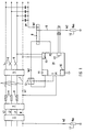
- the installation network in the exemplary embodiment according to FIG. 1 has a house connection 1, a counter 2 and conductor 3, which are protected by short-circuit pre-fuses 4.
- the conductors 3 are further protected by a residual current device 5 and by a circuit breaker 6.
- the installation network has a neutral conductor 7 and an earthing system with equipotential bonding bar 8.
- the equipotential bonding bar 8 is grounded via a grounding conductor 9 at a grounding resistance 10, Rea.
- a test current transmitter 11 is connected to the equipotential bonding bar 8.
- the test current transmitter can in particular be designed as an oscillator.
- the test current from the test current transmitter 11 can be applied to the equipotential bonding bar 8 via a switching device 12 when a clock T is given.
- the potential on the equipotential bonding bar 8 is monitored by a potential measuring device which detects the second potential, P2.
- Another potential measuring device is assigned to the neutral conductor 7 for detecting a first potential, P1.
- the neutral conductor is connected to earth via a grounding conductor at a known grounding resistance of the network supplying the system, Rev.
- a current meter 13 measures the second current, Ie2, flowing through the grounding conductor 9.
- the currents and potentials in a measuring and control unit 14 is detected.
- the measuring and control unit 14 is connected to the mains with its power supply 15.
- a message and control bus can be connected via a bus output 16 be connected.
- For the determination of the earth leakage resistance 10, rea is an existing and the size after known earth resistance 17 of the system supplying Netzes, Rev, included.
- a second potential, P2 which is assigned to the equipotential bonding bar, is again used.
- a first potential, P1 is determined by an earth conductor through an auxiliary earth 18, deer.
- the current, Ie3, through this auxiliary earth 18 is also measured or calculated.
- the current through the auxiliary earth 18, deer is referred to here as a third current, Ie3.
- the current, Ie3, through the auxiliary earth 18, deer also corresponds the current Ie3 emitted by the test current transmitter 11. Instead of that To measure current through the auxiliary earth, the current can also be measured the defined output can be determined by the test current generator 11.
- the earth resistance is 17 of the network supplying the system, Rev, in the provision of earth leakage resistance 10, Rea, not included.
Landscapes
- Physics & Mathematics (AREA)
- General Physics & Mathematics (AREA)
- Measurement Of Resistance Or Impedance (AREA)
- Emergency Protection Circuit Devices (AREA)
Priority Applications (3)
| Application Number | Priority Date | Filing Date | Title |
|---|---|---|---|
| AT97104191T ATE254768T1 (de) | 1997-03-12 | 1997-03-12 | Verfahren zur ermittlung des erdungsableitwiderstandes und dafür eingerichtetes installationsnetz |
| EP97104191A EP0864873B1 (fr) | 1997-03-12 | 1997-03-12 | Procédé pour déterminer la résistance de terre et réseau électrique adapté |
| DE59711030T DE59711030D1 (de) | 1997-03-12 | 1997-03-12 | Verfahren zur Ermittlung des Erdungsableitwiderstandes und dafür eingerichtetes Installationsnetz |
Applications Claiming Priority (1)
| Application Number | Priority Date | Filing Date | Title |
|---|---|---|---|
| EP97104191A EP0864873B1 (fr) | 1997-03-12 | 1997-03-12 | Procédé pour déterminer la résistance de terre et réseau électrique adapté |
Publications (2)
| Publication Number | Publication Date |
|---|---|
| EP0864873A1 true EP0864873A1 (fr) | 1998-09-16 |
| EP0864873B1 EP0864873B1 (fr) | 2003-11-19 |
Family
ID=8226584
Family Applications (1)
| Application Number | Title | Priority Date | Filing Date |
|---|---|---|---|
| EP97104191A Expired - Lifetime EP0864873B1 (fr) | 1997-03-12 | 1997-03-12 | Procédé pour déterminer la résistance de terre et réseau électrique adapté |
Country Status (3)
| Country | Link |
|---|---|
| EP (1) | EP0864873B1 (fr) |
| AT (1) | ATE254768T1 (fr) |
| DE (1) | DE59711030D1 (fr) |
Cited By (5)
| Publication number | Priority date | Publication date | Assignee | Title |
|---|---|---|---|---|
| EP2154782A1 (fr) * | 2008-08-12 | 2010-02-17 | Rolls-Royce plc | Agencement électromécanique |
| CN101937022A (zh) * | 2010-07-28 | 2011-01-05 | 西南交通大学 | 一种双地网接地电阻的测量方法 |
| WO2012156635A1 (fr) * | 2011-05-19 | 2012-11-22 | Renault S.A.S. | Dispositif et procede d'estimation de la resistance du raccordement a la terre d'un appareil electrique |
| WO2012168634A1 (fr) * | 2011-06-08 | 2012-12-13 | Renault S.A.S. | Dispositif et procede correspondant de mesure de la resistance du raccordement a la terre d'un appareil electrique |
| CN110854857A (zh) * | 2019-09-30 | 2020-02-28 | 中国电力科学研究院有限公司 | 一种起振回路及其控制方法 |
Families Citing this family (3)
| Publication number | Priority date | Publication date | Assignee | Title |
|---|---|---|---|---|
| CN102508136A (zh) * | 2011-12-09 | 2012-06-20 | 江苏镇安电力设备有限公司 | 一种配出中性导体的it电力系统绝缘监测方法 |
| CN104502724B (zh) * | 2014-11-05 | 2017-10-13 | 济南鲁智电子科技有限公司 | 一种杆塔接地电阻测量方法 |
| CN106093589B (zh) * | 2016-08-09 | 2018-09-18 | 国网重庆市电力公司南岸供电分公司 | 一种杆塔接地电阻准确测量方法与装置 |
Citations (2)
| Publication number | Priority date | Publication date | Assignee | Title |
|---|---|---|---|---|
| EP0570654A1 (fr) * | 1992-05-20 | 1993-11-24 | P.C.E. S.r.l. | Dispositif de mesure à distance de la résistance de la terre |
| WO1995032434A1 (fr) * | 1994-05-24 | 1995-11-30 | Gustavo Sturaro | Procede d'evaluation de la resistance de terre de l'alimentation dans les systemes tt et dans l'installation de l'utilisateur |
-
1997
- 1997-03-12 AT AT97104191T patent/ATE254768T1/de not_active IP Right Cessation
- 1997-03-12 DE DE59711030T patent/DE59711030D1/de not_active Expired - Fee Related
- 1997-03-12 EP EP97104191A patent/EP0864873B1/fr not_active Expired - Lifetime
Patent Citations (2)
| Publication number | Priority date | Publication date | Assignee | Title |
|---|---|---|---|---|
| EP0570654A1 (fr) * | 1992-05-20 | 1993-11-24 | P.C.E. S.r.l. | Dispositif de mesure à distance de la résistance de la terre |
| WO1995032434A1 (fr) * | 1994-05-24 | 1995-11-30 | Gustavo Sturaro | Procede d'evaluation de la resistance de terre de l'alimentation dans les systemes tt et dans l'installation de l'utilisateur |
Non-Patent Citations (1)
| Title |
|---|
| BRINKS ET AL.: "SYSTEM GROUNDING, PROTECTION AND DETECTION FOR CEMENT PLANTS", IEEE TRANSACTIONS ON INDUSTRY APPLICATIONS, vol. IA-17, no. 6, November 1981 (1981-11-01), NEW YORK US, pages 587 - 596, XP002038528 * |
Cited By (12)
| Publication number | Priority date | Publication date | Assignee | Title |
|---|---|---|---|---|
| EP2154782A1 (fr) * | 2008-08-12 | 2010-02-17 | Rolls-Royce plc | Agencement électromécanique |
| US8427117B2 (en) | 2008-08-12 | 2013-04-23 | Rolls-Royce Plc | Electromechanical arrangement |
| CN101937022A (zh) * | 2010-07-28 | 2011-01-05 | 西南交通大学 | 一种双地网接地电阻的测量方法 |
| CN101937022B (zh) * | 2010-07-28 | 2012-08-22 | 西南交通大学 | 一种双地网接地电阻的测量方法 |
| WO2012156635A1 (fr) * | 2011-05-19 | 2012-11-22 | Renault S.A.S. | Dispositif et procede d'estimation de la resistance du raccordement a la terre d'un appareil electrique |
| FR2975498A1 (fr) * | 2011-05-19 | 2012-11-23 | Renault Sa | Dispositif et procede d'estimation de la resistance du raccordement a la terre d'un appareil electrique |
| CN103608686A (zh) * | 2011-05-19 | 2014-02-26 | 雷诺股份公司 | 用于估计电学装置的接地连接电阻的设备和方法 |
| US9234858B2 (en) | 2011-05-19 | 2016-01-12 | Renault S.A.S. | Device and method for estimating the resistance of the ground connection for an electrical apparatus |
| CN103608686B (zh) * | 2011-05-19 | 2016-03-16 | 雷诺股份公司 | 用于估计电学装置的接地连接电阻的设备和方法 |
| WO2012168634A1 (fr) * | 2011-06-08 | 2012-12-13 | Renault S.A.S. | Dispositif et procede correspondant de mesure de la resistance du raccordement a la terre d'un appareil electrique |
| FR2976361A1 (fr) * | 2011-06-08 | 2012-12-14 | Renault Sa | Dispositif et procede correspondant de mesure de la resistance du raccordement a la terre d'un appareil electrique |
| CN110854857A (zh) * | 2019-09-30 | 2020-02-28 | 中国电力科学研究院有限公司 | 一种起振回路及其控制方法 |
Also Published As
| Publication number | Publication date |
|---|---|
| DE59711030D1 (de) | 2003-12-24 |
| EP0864873B1 (fr) | 2003-11-19 |
| ATE254768T1 (de) | 2003-12-15 |
Similar Documents
| Publication | Publication Date | Title |
|---|---|---|
| DE19960804B4 (de) | Verfahren und Apparat für das Testen eines Leitungskreisunterbrechers für Leitungsstörungen mit Lichtbogenbildung | |
| DE102006022686B4 (de) | Messanordnung zur Ermittlung des Isolationswiderstandes einer elektrischen Vorrichtung oder einer Anlage | |
| KR960006867B1 (ko) | 실제 교류전압 소스의 임피던스 분석방법 및 그 전기 측정장치 | |
| DE69916299T2 (de) | Verfahren und vorrichtung zur erdschlusslokalisierung eines elektrischen kabels | |
| EP2574939B1 (fr) | Appareil de détection de défauts d'isolation et dispositif de localisation de défauts d'isolation dans un réseau d'alimentation de courant non mis à la terre | |
| EP0724980A1 (fr) | Véhicule avec un réseau d'alimentation électrique alimenté par une pile à combustible ou une batterie | |
| DE3819529A1 (de) | Elektrische thermomagnet- und differentialschutzeinrichtung | |
| EP0864873B1 (fr) | Procédé pour déterminer la résistance de terre et réseau électrique adapté | |
| DE19545267C2 (de) | Verfahren zum Gewinnen von fehlerbehaftete Schleifen in einem mehrphasigen elektrischen Energieversorgungsnetz kennzeichnenden Signalen | |
| DE69703759T2 (de) | Verfahren und Apparat zur Fehlerdetektion in der Abschirmung eines abgeschirmten Kabel | |
| AT13822U1 (de) | Überwachungseinrichtung für ein isoliert aufgebautes netz einer photovoltaikanlage | |
| DE2153341C3 (de) | Prüfschaltung zum Feststellen unzulässiger Berührungsspannungen an elektrischen Geräten | |
| DE3237895C2 (fr) | ||
| EP0763745B1 (fr) | Procédé et appareil de test des appareils électriques avec conducteur de terre | |
| DE102009054834A1 (de) | Selbstüberwachende Anschlussleitung und Betriebsmittel | |
| DE102021124432B4 (de) | Erdschlussdetektionsgerät zum Detektieren eines erdfühligen Fehlers in einem Niederspannungskabelnetz | |
| WO2003073577A1 (fr) | Dispositif de controle destine a un disjoncteur comportant un declencheur electronique | |
| EP1001270B1 (fr) | Procédé pour tester une connexion à la terre | |
| DE102022106394B3 (de) | Verfahren und Überwachungseinrichtung zur Bestimmung einesTeil-Isolationswiderstands und einer Teil-Netzableitkapazität in einem verzweigten ungeerdeten Stromversorgungssystem | |
| DE2443351C3 (de) | Strommeßgerät | |
| DE69325381T2 (de) | Sensor zur fehlerstromerfassung | |
| DE3819880C2 (de) | Verfahren zur Feststellung des Verlaufes von unter Spannung stehenden Starkstromleitungen sowie Gerät und Zweipol sich periodisch ändernder Impedanz zur Durchführung des Verfahrens | |
| WO1998026299A1 (fr) | Dispositif de detection d'etat de n condensateurs de puissance appartenant a un groupe de condensateurs haute tension | |
| EP0454013B1 (fr) | Circuit de mesure pour détecter un courant | |
| DE2819776C2 (fr) |
Legal Events
| Date | Code | Title | Description |
|---|---|---|---|
| PUAI | Public reference made under article 153(3) epc to a published international application that has entered the european phase |
Free format text: ORIGINAL CODE: 0009012 |
|
| AK | Designated contracting states |
Kind code of ref document: A1 Designated state(s): AT BE CH DE ES FR GB IT LI NL SE |
|
| AX | Request for extension of the european patent |
Free format text: AL;LT;LV;RO;SI |
|
| 17P | Request for examination filed |
Effective date: 19981005 |
|
| AKX | Designation fees paid |
Free format text: AT BE CH DE ES FR GB IT LI NL SE |
|
| RBV | Designated contracting states (corrected) |
Designated state(s): AT BE CH DE ES FR GB IT LI NL SE |
|
| GRAH | Despatch of communication of intention to grant a patent |
Free format text: ORIGINAL CODE: EPIDOS IGRA |
|
| GRAS | Grant fee paid |
Free format text: ORIGINAL CODE: EPIDOSNIGR3 |
|
| GRAA | (expected) grant |
Free format text: ORIGINAL CODE: 0009210 |
|
| AK | Designated contracting states |
Kind code of ref document: B1 Designated state(s): AT BE CH DE ES FR GB IT LI NL SE |
|
| PG25 | Lapsed in a contracting state [announced via postgrant information from national office to epo] |
Ref country code: NL Free format text: LAPSE BECAUSE OF FAILURE TO SUBMIT A TRANSLATION OF THE DESCRIPTION OR TO PAY THE FEE WITHIN THE PRESCRIBED TIME-LIMIT Effective date: 20031119 Ref country code: IT Free format text: LAPSE BECAUSE OF FAILURE TO SUBMIT A TRANSLATION OF THE DESCRIPTION OR TO PAY THE FEE WITHIN THE PRESCRIBED TIME-LIMIT;WARNING: LAPSES OF ITALIAN PATENTS WITH EFFECTIVE DATE BEFORE 2007 MAY HAVE OCCURRED AT ANY TIME BEFORE 2007. THE CORRECT EFFECTIVE DATE MAY BE DIFFERENT FROM THE ONE RECORDED. Effective date: 20031119 Ref country code: GB Free format text: LAPSE BECAUSE OF FAILURE TO SUBMIT A TRANSLATION OF THE DESCRIPTION OR TO PAY THE FEE WITHIN THE PRESCRIBED TIME-LIMIT Effective date: 20031119 |
|
| REG | Reference to a national code |
Ref country code: GB Ref legal event code: FG4D Free format text: NOT ENGLISH |
|
| REG | Reference to a national code |
Ref country code: CH Ref legal event code: EP |
|
| REF | Corresponds to: |
Ref document number: 59711030 Country of ref document: DE Date of ref document: 20031224 Kind code of ref document: P |
|
| PG25 | Lapsed in a contracting state [announced via postgrant information from national office to epo] |
Ref country code: SE Free format text: LAPSE BECAUSE OF FAILURE TO SUBMIT A TRANSLATION OF THE DESCRIPTION OR TO PAY THE FEE WITHIN THE PRESCRIBED TIME-LIMIT Effective date: 20040219 |
|
| PG25 | Lapsed in a contracting state [announced via postgrant information from national office to epo] |
Ref country code: ES Free format text: LAPSE BECAUSE OF FAILURE TO SUBMIT A TRANSLATION OF THE DESCRIPTION OR TO PAY THE FEE WITHIN THE PRESCRIBED TIME-LIMIT Effective date: 20040302 |
|
| PG25 | Lapsed in a contracting state [announced via postgrant information from national office to epo] |
Ref country code: AT Free format text: LAPSE BECAUSE OF NON-PAYMENT OF DUE FEES Effective date: 20040312 |
|
| PG25 | Lapsed in a contracting state [announced via postgrant information from national office to epo] |
Ref country code: LI Free format text: LAPSE BECAUSE OF NON-PAYMENT OF DUE FEES Effective date: 20040331 Ref country code: CH Free format text: LAPSE BECAUSE OF NON-PAYMENT OF DUE FEES Effective date: 20040331 Ref country code: BE Free format text: LAPSE BECAUSE OF NON-PAYMENT OF DUE FEES Effective date: 20040331 |
|
| NLV1 | Nl: lapsed or annulled due to failure to fulfill the requirements of art. 29p and 29m of the patents act | ||
| GBV | Gb: ep patent (uk) treated as always having been void in accordance with gb section 77(7)/1977 [no translation filed] |
Effective date: 20031119 |
|
| ET | Fr: translation filed | ||
| PLBE | No opposition filed within time limit |
Free format text: ORIGINAL CODE: 0009261 |
|
| STAA | Information on the status of an ep patent application or granted ep patent |
Free format text: STATUS: NO OPPOSITION FILED WITHIN TIME LIMIT |
|
| BERE | Be: lapsed |
Owner name: *SIEMENS A.G. Effective date: 20040331 |
|
| 26N | No opposition filed |
Effective date: 20040820 |
|
| REG | Reference to a national code |
Ref country code: CH Ref legal event code: PL |
|
| PGFP | Annual fee paid to national office [announced via postgrant information from national office to epo] |
Ref country code: FR Payment date: 20050331 Year of fee payment: 9 |
|
| PGFP | Annual fee paid to national office [announced via postgrant information from national office to epo] |
Ref country code: DE Payment date: 20050519 Year of fee payment: 9 |
|
| PG25 | Lapsed in a contracting state [announced via postgrant information from national office to epo] |
Ref country code: DE Free format text: LAPSE BECAUSE OF NON-PAYMENT OF DUE FEES Effective date: 20061003 |
|
| REG | Reference to a national code |
Ref country code: FR Ref legal event code: ST Effective date: 20061130 |
|
| PG25 | Lapsed in a contracting state [announced via postgrant information from national office to epo] |
Ref country code: FR Free format text: LAPSE BECAUSE OF NON-PAYMENT OF DUE FEES Effective date: 20060331 |