EP0864900A2 - Adaptateur de branchement/débranchement rapide - Google Patents
Adaptateur de branchement/débranchement rapide Download PDFInfo
- Publication number
- EP0864900A2 EP0864900A2 EP97306703A EP97306703A EP0864900A2 EP 0864900 A2 EP0864900 A2 EP 0864900A2 EP 97306703 A EP97306703 A EP 97306703A EP 97306703 A EP97306703 A EP 97306703A EP 0864900 A2 EP0864900 A2 EP 0864900A2
- Authority
- EP
- European Patent Office
- Prior art keywords
- section
- adapter mechanism
- clip
- cylindrical
- recited
- Prior art date
- Legal status (The legal status is an assumption and is not a legal conclusion. Google has not performed a legal analysis and makes no representation as to the accuracy of the status listed.)
- Granted
Links
Images
Classifications
-
- G—PHYSICS
- G02—OPTICS
- G02B—OPTICAL ELEMENTS, SYSTEMS OR APPARATUS
- G02B23/00—Telescopes, e.g. binoculars; Periscopes; Instruments for viewing the inside of hollow bodies; Viewfinders; Optical aiming or sighting devices
- G02B23/24—Instruments or systems for viewing the inside of hollow bodies, e.g. fibrescopes
- G02B23/2476—Non-optical details, e.g. housings, mountings, supports
- G02B23/2484—Arrangements in relation to a camera or imaging device
-
- G—PHYSICS
- G02—OPTICS
- G02B—OPTICAL ELEMENTS, SYSTEMS OR APPARATUS
- G02B23/00—Telescopes, e.g. binoculars; Periscopes; Instruments for viewing the inside of hollow bodies; Viewfinders; Optical aiming or sighting devices
- G02B23/24—Instruments or systems for viewing the inside of hollow bodies, e.g. fibrescopes
-
- G—PHYSICS
- G02—OPTICS
- G02B—OPTICAL ELEMENTS, SYSTEMS OR APPARATUS
- G02B23/00—Telescopes, e.g. binoculars; Periscopes; Instruments for viewing the inside of hollow bodies; Viewfinders; Optical aiming or sighting devices
- G02B23/24—Instruments or systems for viewing the inside of hollow bodies, e.g. fibrescopes
- G02B23/2476—Non-optical details, e.g. housings, mountings, supports
-
- Y—GENERAL TAGGING OF NEW TECHNOLOGICAL DEVELOPMENTS; GENERAL TAGGING OF CROSS-SECTIONAL TECHNOLOGIES SPANNING OVER SEVERAL SECTIONS OF THE IPC; TECHNICAL SUBJECTS COVERED BY FORMER USPC CROSS-REFERENCE ART COLLECTIONS [XRACs] AND DIGESTS
- Y10—TECHNICAL SUBJECTS COVERED BY FORMER USPC
- Y10T—TECHNICAL SUBJECTS COVERED BY FORMER US CLASSIFICATION
- Y10T403/00—Joints and connections
- Y10T403/32—Articulated members
- Y10T403/32606—Pivoted
- Y10T403/32861—T-pivot, e.g., wrist pin, etc.
- Y10T403/32893—T-pivot, e.g., wrist pin, etc. including distinct pin retainer
-
- Y—GENERAL TAGGING OF NEW TECHNOLOGICAL DEVELOPMENTS; GENERAL TAGGING OF CROSS-SECTIONAL TECHNOLOGIES SPANNING OVER SEVERAL SECTIONS OF THE IPC; TECHNICAL SUBJECTS COVERED BY FORMER USPC CROSS-REFERENCE ART COLLECTIONS [XRACs] AND DIGESTS
- Y10—TECHNICAL SUBJECTS COVERED BY FORMER USPC
- Y10T—TECHNICAL SUBJECTS COVERED BY FORMER US CLASSIFICATION
- Y10T403/00—Joints and connections
- Y10T403/32—Articulated members
- Y10T403/32606—Pivoted
- Y10T403/32861—T-pivot, e.g., wrist pin, etc.
- Y10T403/32893—T-pivot, e.g., wrist pin, etc. including distinct pin retainer
- Y10T403/32901—Unitary clip or plug
-
- Y—GENERAL TAGGING OF NEW TECHNOLOGICAL DEVELOPMENTS; GENERAL TAGGING OF CROSS-SECTIONAL TECHNOLOGIES SPANNING OVER SEVERAL SECTIONS OF THE IPC; TECHNICAL SUBJECTS COVERED BY FORMER USPC CROSS-REFERENCE ART COLLECTIONS [XRACs] AND DIGESTS
- Y10—TECHNICAL SUBJECTS COVERED BY FORMER USPC
- Y10T—TECHNICAL SUBJECTS COVERED BY FORMER US CLASSIFICATION
- Y10T403/00—Joints and connections
- Y10T403/59—Manually releaseable latch type
-
- Y—GENERAL TAGGING OF NEW TECHNOLOGICAL DEVELOPMENTS; GENERAL TAGGING OF CROSS-SECTIONAL TECHNOLOGIES SPANNING OVER SEVERAL SECTIONS OF THE IPC; TECHNICAL SUBJECTS COVERED BY FORMER USPC CROSS-REFERENCE ART COLLECTIONS [XRACs] AND DIGESTS
- Y10—TECHNICAL SUBJECTS COVERED BY FORMER USPC
- Y10T—TECHNICAL SUBJECTS COVERED BY FORMER US CLASSIFICATION
- Y10T403/00—Joints and connections
- Y10T403/59—Manually releaseable latch type
- Y10T403/591—Manually releaseable latch type having operating mechanism
Definitions
- This invention generally relates to an adapter for an optical instrument and in particular to an adapter that provides for a quick attachment and release of an eyepiece from a B-mount instrument.
- Eyepieces are associated with a number of optical devices including, as examples, endoscopes and boroscopes.
- endoscope generally denotes a class of optical devices used for examining the internal cavities of the human body.
- borescope generally denotes a class of analogous devices for examining internal cavities in machinery or other nonhuman areas.
- Endoscopes and boroscopes have the same basic structure. Each contains an objective lens for gathering an image, one or more intermediate relay lenses or fiber optics for relaying the image through an elongated tube and eyepiece optics for allowing an individual to view the image directly.
- eyepiece optics in endoscopes and boroscopes generally have a similar basic construction.
- eyepiece optics include an eyepiece housing with a central cavity for any optical elements required by the eyepiece. Externally the eyepiece housing has a neck portion for attachment to an elongated tube from the endoscope or borescope.
- a frusto-conical or other conoidally-shaped housing section then flares from its distal end to a proximal end and terminates at a cylindrical peripheral flange portion.
- an individual places his or her eye at this peripheral flange portion, that may or may not contain a viewing window.
- the Jones patent discloses an endoscope eyepiece with an opto-mechanical coupler.
- a spring-biased cam ring mounted on the coupler rotates to retract retaining studs and integral heads radially outward. When the studs are retracted the eyepiece can pass between the heads for connection to or separation from the eyepiece.
- a spring biases it to a stable position and thereby moves the studs radially inward until the heads engage the flared surface of the eyepiece housing. This action clamps the eyepiece to and centers the eyepiece on the coupler.
- the Tawara patent discloses an endoscope accessory mounting device, or coupler, with a spring-biased cam ring that controls the position of axially aligned, radially extending plate cams.
- the cam ring When the cam ring is rotated, the eyepiece can freely pass into or separate from an eyepiece receiving socket in the accessory mounting device.
- springs displace the cam ring to its stable position and the cam plates rotate into engagement with the flared surface of the eyepiece thereby to clamp and center the accessory mounting device with respect to the eyepiece.
- the Tawara patent also discloses an endoscope coupler with spring-biased axially aligned cam plates that are biased against a radially acting spring biased plunger.
- the eyepiece snaps into the coupler by driving the cam plates away from a central axis and compressing the springs on the cam plates.
- the springs drive the cam plates against the flared surface of the eyepiece to clamp and center the coupler with respect to the eyepiece.
- An individual compresses the radially acting, diametrically opposed plungers to move the cam plates to an open position when it is desired to separate the coupler from the eyepiece.
- the Hori patent discloses an optical mechanical coupler with a C-shaped clamping member that is axially displaced from a clamping surface and operated by a locking ring or clamp member.
- the clamp member rotates to one extreme position it axially displaces the C-shaped clamping member from the clamping surface.
- An eyepiece can then be inserted from the side.
- a reverse rotation of the clamp member displaces the C-shaped clamping member into the eyepiece thereby to clamp and center the coupler with respect to the eyepiece.
- the retaining means comprises a circular ring having the lever means at a first end and a hook means at a second end for securing the retaining means within the cylindrical chamber.
- the retaining means comprises a C-clip means having a chamfered edge means for enabling the first device to snap into the adapter mechanism.
- the cylindrical chamber means comprises a guide post and the retainer means comprises an elongated slot for receiving the guide post into the slot, thereby limiting the radial movement of the retaining means as the lever means is moved in a direction to release the first device.
- the back plate means comprises a rear section having a radially extending cylindrical section of lesser radial distance than the cylindrical chamber means, the rear section having a fixed post protruding away from the cylindrical section and positioned a predetermined distance from the lever means to enable the first device to be quickly released from the adapter mechanism using the fingers of one hand.
- the C-clip means extends through an arc of approximately 350 degrees.
- the retainer means comprises material means for providing an elastic force to grip an interfacing device inserted in the adapter mechanism.
- the retainer means comprises acetal compounds such as delrin material.
- the second end portion comprises a rear section having an opening for attaching to the second device and enabling passage of the image.
- the rear section of the end portion comprises a plurality cf holes surrounding the opening for air venting.
- the objects are further accomplished by providing a method of attaching a first device to a second device with a quick attach/release mechanism for enabling an image transmitted from the first device along an optical axis to the second device, comprising the steps of securing a first end portion of a back plate means of the quick/attach release mechanism to the second device and a second end portion spaced along an adapter axis to the first device, providing at the second end portion of the back plate means a radially extending cylindrical chamber means for receiving the first device, securing the eyepiece within the back plate means with retaining means positioned within the cylindrical chamber means, and providing a lever means extending through the cylindrical chamber means to enable the first device to be quickly released from the mechanism.
- the step of the retaining means being positioned within the cylindrical chamber means comprises the step of providing a C-clip having the lever means at a first end of the C-clip and a hook means at a second end of the C-clip.
- the step of providing the C-clip further comprises the step of providing a chamfered edge on the C-clip for enabling the first device to snap into the adapter mechanism.
- a quick release adapter mechanism for interfacing a first device to a second device
- a first section of the adapter mechanism having an inner axially extending cylindrical wall including threaded means on an upper portion of the wall for attachment to a first device
- the cylindrical wall comprises a first portion having a larger outer diameter wall than a second portion
- seal means positioned around the circumference of the second portion of the cylindrical wall and adjacent to an end of the larger diameter first portion for providing a tight fit between the first section and the second section of the adapter mechanism
- the second portion of the inner cylindrical wall of the first section comprises a groove around the outer circumference of the second portion for receiving the second section of the adapter mechanism
- the second section comprises an upper portion having a C-clip means for insertion into the groove of the second portion of the first section securing the second section to the first section
- the second section comprises a lower portion having a first threaded cylindrical wall with the same diameter as the first section cylindrical wall
- the C-clip means comprises a lever protruding through the cylindrical
- the cylindrical wall of the first section comprises an outer chamfered edge at a lower end adjacent to the groove for enabling the first section to snap into the second section.
- the seal means comprises an O-ring.
- the C-clip means comprises a chamfered edge for enabling the C-clip to snap into the groove around the circumference of the second portion of the first section.
- the C-clip comprises material means for providing an elastic force to grip the groove.
- the second section of the adapter mechanism comprises a transition area between the outer cylindrical upper portion and the outer cylindrical lower portion, the cylindrical upper portion being of greater outside diameter than the cylindrical lower portion, the transition area comprises a plurality of equal holes for providing air venting.
- a method for interfacing a first device to a second device comprising a quick release adapter mechanism comprising the steps of attaching a first section of the adapter mechanism, having an inner axially extending cylindrical wall including threaded means on an upper portion of the wall, to a first device, providing the cylindrical wall with a first portion having a larger outer diameter wall than a second portion, positioning a seal means around the circumference of the second portion of the cylindrical wall and adjacent to an end of the larger diameter first portion thereby providing a tight fit between the first section and the second section of the adapter mechanism, providing a groove around the outer circumference of the second portion of the inner cylindrical wall of the first section for receiving the second section of the adapter mechanism, inserting a C-clip means of an upper portion of the second section into the groove of the second portion of the first section thereby securing the second section to the first section, providing in a lower portion of the second section a first threaded inner cylindrical wall with the same diameter as the first section inner cylindrical wall, and providing a
- the method comprises the step of providing on the cylindrical wall of the first section an outer chamfered edge at a lower end adjacent to the groove for enabling the first section to snap into the section.
- the step of positioning the seal means around the circumference of the cylindrical wall includes the step of positioning an O-ring for the seal means.
- the step of inserting the C-clip means comprises the steps of providing a chamfered edge on the C-clip means for enabling the C-clip to snap into the groove around the circumference of the second portion of the first section.
- the method further comprises the step of providing a transition area on the second section of the adapter mechanism between the outer cylindrical upper portion and the outer cylindrical lower portion, the cylindrical upper portion being of greater outside diameter than the cylindrical lower portion, the transition area having a plurality of equal by spaced holes for providing air venting.
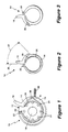
- FIG. 1 an elevational end view of the invention of a quick attach/release adapter mechanism 10 is shown comprising a rigid back plate 12 and a C-clip retainer 14 with a portion of the chamber 17 and wall 13 of the back plate 12 cut away exposing the C-clip retainer 14 starting at point A.
- the back plate 12 provides for permanent attachment of the adapter mechanism to a suitable device.
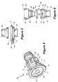
- the C-clip retainer 14 is positioned within a circumferential chamber 17 (see FIG. 4) of the back plate 12 and acts as a locking ring under the elastic force of the C-clip retainer 14 material to provide a grip around an interfacing instrument when installed within the adapter mechanism 10.
- a guide post 28 located within the back plate chamber 17 fits into the slot 26 to guide the C-clip retainer 14 as the lever 16 is moved toward the guide post 28 causing the C-clip retainer 14 to move outwardly within the chamber 17 of the back plate 12.
- the hook 22 end of the C-clip retainer 14 is placed over a fixed post 24 and secures the C-clip retainer 14 at a fixed point so that it will move outwardly within the chamber 17 when the lever 16 is moved.
- a rear view of the C-clip retainer 14 is shown in FIG. 3.
- the depth of the retainer 14 is approximately 0.110 inches.
- the present embodiment of retainer 14 is made of an acetal compound such as marketed under the name Delrin ® which is well known in the art; it may also be made from various moldable or machineable materials of plastics having similar properties.
- the end 42 of the endoscope 40 may be placed into the adapter mechanism 10 when the lever 16 is moved toward the fixed post 18, and when the lever 16 is released, the C-clip retainer 14 ring grips around a truncated conical back surface 44 of the end 42 of the endoscope 40 applying equal pressure around the circumference of the endoscope 40, thereby holding and properly positioning the endoscope 40, in front of the eyepiece 30. Because of the conical or radius common on the interfacing instrument such as B-mount eyepieces, the eyepiece tends to center itself within the quick release adapter mechanism 10.
- FIG. 5 is a partially exploded view of the adapter mechanism 10 showing a side view of the back plate 12 and the proximate end of the endoscope 40.
- the chamber 17 which encloses the C-clip retainer 14 is shown with the lever 16 portion of the C-clip protruding from an opening in the top of the chamber 17.
- a rear section 15 of the back plate 12 has an opening 19 for attaching the adapter mechanism 12 to a device such as the imaging coupler 32 shown in FIG. 4.
- the fixed post la is shown protruding from the side of the rear section 15.
- Eight holes 21 (0.125 in.) are equally positioned every 45 degrees around a circle surrounding the opening 19 in which the imaging coupler 32 is attached.
- FIG. 6 a partially exploded view of an alternate embodiment of a quick release apparatus 50 is shown having an open cylindrical portion 53.
- the quick release apparatus 50 comprises an upper section 52 and a lower section 54.
- the lower section 54 includes an opening 56 having a lever 59 protruding through it which when moved sideways causes the upper section 52 to be quickly released from the lower section 54.
- An O-ring 60 provides for a tight fitting when the upper section 52 is attached to the lower section 54.
- C-clip 58 is installed into lower section 34 so that the lever 59 of C-clip 58 is protruding out from a side slot 56 in the lower section 54.
- C-clip 58 is a smaller version of C-clip 14 in FIG.
- the upper section 52 is a custom connection designed to fit into lower section 54.
- the taper 66 on the end of upper section 52 expands the C-clip 58 when installed into lower section 54.
- the C-clip 58 falls into a circular chamber 64 connecting lower section 54 with upper section 52.
- the joined lower section 54 and upper section 52 can only be disassembled when the lever 59 on C-clip 58 is moved sideways opening the C-clip 58.
- O-ring 60 provides a tight fit and sealing properties between upper section 52 and lower section 54.
- the lower cylindrical end 74 of lower section 54 can be configured to mount to any appropriate in-line components.
- the lower cylindrical end 74 of the embodiment shown in FIG. 6 comprises a smaller diameter portion adjacent to the holes 76 and then the lower cylindrical end 74 expands approximately at the midpoint to a larger diameter portion with the outside diameter remaining the same for the smaller diameter portion and the larger diameter portion each. of which is threaded for screwing into mating devices.
- the lower cylindrical end 74 of the embodiment shown in FIG. 6 comprises a threaded inside diameter (not shown).
- a tapered portion 72 of lower section 54 comprises 8 holes 76 spaced 45 degrees apart for providing venting for eyepiece applications.
- the quick release apparatus 50 enables the coupling together cf two optical components attached to the end of each section 52 and 54.
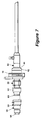
- FIG. 7 a partially exploded side view of an endoscope 40 seated in one end of an eyepiece 30 by means of the quick attach/release mechanism 10 with the other end of the eyepiece 30 attached to one section 52 of the alternate embodiment quick release apparatus 50.
- the lower section 54 of the quick release apparatus 50 may be coupled to a device such as a camera lens 64.
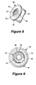
- a perspective view of the upper section 52 of the alternate embodiment shows the open cylindrical center portion having threads 63 on a narrower inner portion 53 of the cylindrical surface contiguous to a wider inner portion 65 of the cylinder near the top of the hollow upper section 52.
- FIG. 9 a top view of the lower section 54 of the alternate embodiment is shown.
- the C-clip 58 is partially extending outside of its cylindrical groove in the cylindrical wall.
- the lever 59 of the C-clip 58 extends through the side wall of lower section 54.
- a rib 80 around the perimeter of the device provides for gripping the lower section 54 of the quick release apparatus 53.
- the open cylindrical center portion 53 continues through the lower section 54.
Landscapes
- Physics & Mathematics (AREA)
- Astronomy & Astrophysics (AREA)
- General Physics & Mathematics (AREA)
- Optics & Photonics (AREA)
- Engineering & Computer Science (AREA)
- Multimedia (AREA)
- Endoscopes (AREA)
- Instruments For Viewing The Inside Of Hollow Bodies (AREA)
- Mechanical Coupling Of Light Guides (AREA)
- Apparatus For Radiation Diagnosis (AREA)
- Microscoopes, Condenser (AREA)
Applications Claiming Priority (2)
| Application Number | Priority Date | Filing Date | Title |
|---|---|---|---|
| US08/769,954 US5772355A (en) | 1996-12-19 | 1996-12-19 | Quick attach/release adapter mechanism |
| US769954 | 1996-12-19 |
Publications (3)
| Publication Number | Publication Date |
|---|---|
| EP0864900A2 true EP0864900A2 (fr) | 1998-09-16 |
| EP0864900A3 EP0864900A3 (fr) | 1999-03-24 |
| EP0864900B1 EP0864900B1 (fr) | 2003-04-02 |
Family
ID=25087025
Family Applications (1)
| Application Number | Title | Priority Date | Filing Date |
|---|---|---|---|
| EP97306703A Expired - Lifetime EP0864900B1 (fr) | 1996-12-19 | 1997-09-01 | Adaptateur de branchement/débranchement rapide |
Country Status (8)
| Country | Link |
|---|---|
| US (2) | US5772355A (fr) |
| EP (1) | EP0864900B1 (fr) |
| JP (1) | JPH10197804A (fr) |
| KR (1) | KR19980063363A (fr) |
| DE (1) | DE69720411T2 (fr) |
| MY (1) | MY116910A (fr) |
| SG (1) | SG60076A1 (fr) |
| TW (1) | TW355226B (fr) |
Families Citing this family (39)
| Publication number | Priority date | Publication date | Assignee | Title |
|---|---|---|---|---|
| US5772355A (en) * | 1996-12-19 | 1998-06-30 | Precision Optics Corporation | Quick attach/release adapter mechanism |
| US6102556A (en) * | 1998-04-21 | 2000-08-15 | Panavision, Inc. | Detachable light filter holder |
| US6203237B1 (en) * | 1998-10-08 | 2001-03-20 | Lockheed Martin Corporation | Apparatus for releasably connecting first and second structures together |
| US6427858B2 (en) * | 1999-01-19 | 2002-08-06 | Pro-Mart Industries, Inc. | Laundry drying rack |
| ITBZ20010005U1 (it) * | 2000-03-21 | 2002-09-20 | Nestle & Fischer Gmbh & Co Kg | Dispositivo di serraggio per livelli. |
| EP1301118B1 (fr) | 2000-07-14 | 2006-09-06 | Xillix Technologies Corp. | Systeme video compact d'endoscopie en fluorescence |
| US6695772B1 (en) | 2001-11-26 | 2004-02-24 | Visionary Biomedical, Inc. | Small diameter cannula devices, systems and methods |
| US20060241496A1 (en) | 2002-01-15 | 2006-10-26 | Xillix Technologies Corp. | Filter for use with imaging endoscopes |
| US6893184B2 (en) | 2002-03-08 | 2005-05-17 | The Boeing Company | Positive lock pin |
| US6752562B2 (en) | 2002-03-08 | 2004-06-22 | The Boeing Company | Quick install positive lock pin |
| US6786669B2 (en) | 2002-03-08 | 2004-09-07 | The Boeing Company | Positive lock quick release pin |
| WO2007106624A2 (fr) | 2006-02-07 | 2007-09-20 | Novadaq Technologies Inc. | Imagerie proche infrarouge |
| JP4948602B2 (ja) * | 2006-07-28 | 2012-06-06 | ノバダック テクノロジーズ インコーポレイテッド | 内視鏡の対物部において光学部材を堆積及び除去するシステム、及びその方法 |
| US8498695B2 (en) | 2006-12-22 | 2013-07-30 | Novadaq Technologies Inc. | Imaging system with a single color image sensor for simultaneous fluorescence and color video endoscopy |
| EP3117765B1 (fr) | 2008-03-18 | 2021-10-27 | Stryker European Operations Limited | Système d'imagerie par réflexion couleur et proche infrarouge combinées |
| US8286810B2 (en) * | 2010-02-10 | 2012-10-16 | Pro-Mart Industries, Inc | Laundry rack |
| BRPI1001388A2 (pt) | 2010-05-05 | 2011-12-27 | Whirlpool Sa | sistema de controle para pistço de compressor linear ressonante, mÉtodo de controle para pistço de compressor linear ressonante e compressor linear ressonante |
| BRPI1013472B1 (pt) | 2010-07-14 | 2019-10-22 | Embraco Ind De Compressores E Solucoes Em Refrigeracao Ltda | método de controle para um compressor linear ressonante e sistema de controle eletrônico para um compressor linear ressonante aplicados a um sistema de refrigeração |
| DE102010035027A1 (de) * | 2010-08-20 | 2012-02-23 | Voss Automotive Gmbh | Verriegelungselement für einen Steckverbinder und Steckverbinder mit einem solchen Verriegelungselement |
| RU2607645C9 (ru) | 2011-03-08 | 2017-07-25 | Новадак Текнолоджис Инк. | Светодиодное осветительное устройство полного спектра |
| BRPI1103776B1 (pt) | 2011-08-19 | 2018-12-04 | Whirlpool Sa | sistema e método de controle de curso e operação em frequência de ressonância de um motor linear rossonante |
| WO2013131013A1 (fr) * | 2012-03-02 | 2013-09-06 | Designport, Inc. | Coupleurs de lunette optique |
| US9140466B2 (en) | 2012-07-17 | 2015-09-22 | Eemax, Inc. | Fluid heating system and instant fluid heating device |
| US10222091B2 (en) | 2012-07-17 | 2019-03-05 | Eemax, Inc. | Next generation modular heating system |
| JP6049398B2 (ja) * | 2012-10-24 | 2016-12-21 | 東京エレクトロン株式会社 | ヒータ装置 |
| WO2014098943A1 (fr) * | 2012-12-21 | 2014-06-26 | Eemax, Inc. | Chauffe-eau à fil nu de nouvelle génération |
| US9795279B2 (en) | 2013-10-21 | 2017-10-24 | Access Optics, LLC | Endoscope coupler |
| AU2015364502B2 (en) | 2014-12-17 | 2017-12-14 | Rheem Manufacturing Company | Tankless electric water heater |
| US10881408B2 (en) * | 2015-04-22 | 2021-01-05 | Covidien Lp | Interlock assembly for replaceable loading units |
| EP4442222A3 (fr) | 2015-11-13 | 2024-12-18 | Stryker Corporation | Systèmes et procédés d'éclairage et d'imagerie d'une cible |
| EP4155716A1 (fr) | 2016-01-26 | 2023-03-29 | Stryker European Operations Limited | Arrangement de capteur d'image |
| CN105520708B (zh) * | 2016-01-27 | 2017-01-18 | 浙江优亿医疗器械有限公司 | 一种快接式电子可视内窥镜装置 |
| US10293122B2 (en) | 2016-03-17 | 2019-05-21 | Novadaq Technologies ULC | Endoluminal introducer with contamination avoidance |
| US10371299B2 (en) | 2016-04-18 | 2019-08-06 | Mann+Hummel Gmbh | Quick connector with anti-rotate feature |
| USD916294S1 (en) | 2016-04-28 | 2021-04-13 | Stryker European Operations Limited | Illumination and imaging device |
| WO2017214730A1 (fr) | 2016-06-14 | 2017-12-21 | Novadaq Technologies Inc. | Procédés et systèmes d'imagerie adaptative pour l'amélioration des signaux en faible lumière dans la visualisation médicale |
| EP4242743A3 (fr) | 2017-02-10 | 2023-10-18 | Stryker European Operations Limited | Systèmes et procédés d'imagerie à fluorescence portative à champ ouvert |
| DE102018107357A1 (de) * | 2018-03-28 | 2019-10-02 | Aesculap Ag | Montageadapter zur Befestigung eines Sterilüberzugs an einem Mikroskop, Mikroskop zur Verwendung mit einem derartigen Adapter sowie System mit einem deratigen Mikroskop und einem derartigen Adapter |
| US10626646B1 (en) * | 2019-05-21 | 2020-04-21 | Ford Global Technologies, Llc | Self-contained door hinge release |
Family Cites Families (24)
| Publication number | Priority date | Publication date | Assignee | Title |
|---|---|---|---|---|
| US1369687A (en) * | 1919-10-04 | 1921-02-22 | William W Martin | Lubricator |
| US2032866A (en) * | 1934-12-19 | 1936-03-03 | Fairchild Aerial Camera Corp | Lens case locking device |
| US2595787A (en) * | 1947-03-12 | 1952-05-06 | Waldes Kohinoor Inc | Retaining ring assembly |
| US2521127A (en) * | 1948-05-08 | 1950-09-05 | Wright Aeronautical Corp | Fluid tight joint |
| US2805089A (en) * | 1954-12-30 | 1957-09-03 | Hansen Mfg Co | Pipe coupling with wedged spring ring detent means |
| US3070389A (en) * | 1956-09-14 | 1962-12-25 | Agfa Ag Fa | Structure for removable connecting a device to a support therefor |
| US3314696A (en) * | 1964-02-11 | 1967-04-18 | Perfecting Service Company | Quick connect coupling |
| CH446752A (fr) * | 1966-11-03 | 1967-11-15 | Paillard Sa | Dispositif de blocage d'un élément optique réglable |
| US3523701A (en) * | 1967-11-24 | 1970-08-11 | Gra Tec Inc | Coupling unit |
| US4066330A (en) * | 1976-06-14 | 1978-01-03 | Karl Storz Endoscopy-America, Inc. | Coupler for joining optical devices |
| US4281895A (en) * | 1979-04-12 | 1981-08-04 | Quantor Corporation | Quick change lens mount |
| JPS55136037A (en) * | 1979-04-12 | 1980-10-23 | Olympus Optical Co | Device for connecting accessory for endoscope |
| US4249799A (en) * | 1979-04-27 | 1981-02-10 | The Iglesias Trust | Connector for optical devices |
| JPS55168306U (fr) * | 1979-05-23 | 1980-12-03 | ||
| US4264167A (en) * | 1980-02-04 | 1981-04-28 | Polaroid Corporation | Adapter for coupling a camera with a viewing device |
| US4423892A (en) * | 1980-10-29 | 1984-01-03 | Bartholomew Donald D | Swivelable quick connector assembly |
| JPS57130808U (fr) * | 1981-02-09 | 1982-08-14 | ||
| JPS61141416A (ja) * | 1984-12-14 | 1986-06-28 | Machida Seisakusho:Kk | 内視鏡と撮影装置との接続装置 |
| US4740058A (en) * | 1986-08-29 | 1988-04-26 | Technology For Imaging, Inc. | Coupler for optical instruments |
| JPH0622806Y2 (ja) * | 1989-09-27 | 1994-06-15 | パイオニア株式会社 | レンズフレーム |
| US5205280A (en) * | 1990-12-21 | 1993-04-27 | Mp Video, Inc. | Quick-release endoscopic coupling assembly |
| US5406418A (en) * | 1993-07-15 | 1995-04-11 | Precision Optics Corporation | Mechanical coupler for eyepieces |
| US5617257A (en) * | 1995-07-11 | 1997-04-01 | The United States Of America As Represented By The Secretary Of The Navy | Variable focus adapter |
| US5772355A (en) * | 1996-12-19 | 1998-06-30 | Precision Optics Corporation | Quick attach/release adapter mechanism |
-
1996
- 1996-12-19 US US08/769,954 patent/US5772355A/en not_active Expired - Lifetime
-
1997
- 1997-06-12 MY MYPI97002615A patent/MY116910A/en unknown
- 1997-06-20 SG SG1997002114A patent/SG60076A1/en unknown
- 1997-07-04 KR KR1019970030913A patent/KR19980063363A/ko not_active Ceased
- 1997-09-01 DE DE69720411T patent/DE69720411T2/de not_active Expired - Fee Related
- 1997-09-01 EP EP97306703A patent/EP0864900B1/fr not_active Expired - Lifetime
- 1997-12-16 TW TW086119015A patent/TW355226B/zh active
- 1997-12-19 JP JP9351467A patent/JPH10197804A/ja active Pending
-
1998
- 1998-01-22 US US09/010,645 patent/US5897269A/en not_active Expired - Lifetime
Also Published As
| Publication number | Publication date |
|---|---|
| KR19980063363A (ko) | 1998-10-07 |
| EP0864900B1 (fr) | 2003-04-02 |
| SG60076A1 (en) | 1999-02-22 |
| DE69720411T2 (de) | 2004-01-08 |
| HK1015464A1 (en) | 1999-10-15 |
| EP0864900A3 (fr) | 1999-03-24 |
| US5772355A (en) | 1998-06-30 |
| TW355226B (en) | 1999-04-01 |
| MY116910A (en) | 2004-04-30 |
| JPH10197804A (ja) | 1998-07-31 |
| US5897269A (en) | 1999-04-27 |
| DE69720411D1 (de) | 2003-05-08 |
Similar Documents
| Publication | Publication Date | Title |
|---|---|---|
| US5772355A (en) | Quick attach/release adapter mechanism | |
| US4740058A (en) | Coupler for optical instruments | |
| US5264928A (en) | Universal adapter for mounting cameras to microscopes | |
| US5205280A (en) | Quick-release endoscopic coupling assembly | |
| US4844071A (en) | Endoscope coupler device | |
| US5455711A (en) | Magnification lens coupling device for a night vision assembly | |
| EP0076937A2 (fr) | Dispositif de couplage pour une caméra de télévision endoscopique | |
| EP2428829B1 (fr) | Dispositif à lentille échangeable | |
| US7648291B2 (en) | Optical adapter system and method | |
| JPS6337310A (ja) | 内視鏡先端部 | |
| US7309311B2 (en) | Endoscopic observation apparatus and medical device holder | |
| WO2001041631A1 (fr) | Dispositif de prises de vues destine a un endoscope | |
| US5406418A (en) | Mechanical coupler for eyepieces | |
| WO2017047229A1 (fr) | Dispositif de lentille, système d'appareil photo, et unité de correction d'aberration | |
| US6007255A (en) | Adapter assembly for light source | |
| JP3560884B2 (ja) | 内視鏡用撮像装置 | |
| US7510340B2 (en) | Optical adaptor system and method | |
| HK1015464B (en) | Quick attach/release adapter mechanism | |
| JPH0627393A (ja) | 観察装置 | |
| JP3934975B2 (ja) | デジタルカメラ用アダプタ | |
| US4655569A (en) | Optical eyepiece adaptor for cameras | |
| JP3089950B2 (ja) | 内視鏡の光源装置 | |
| JP3212774B2 (ja) | 内視鏡 | |
| WO1995018983A1 (fr) | Procede et appareil pour sous-ensemble de microscope | |
| JP2002116383A (ja) | 顕微鏡用リレーレンズ装置 |
Legal Events
| Date | Code | Title | Description |
|---|---|---|---|
| PUAI | Public reference made under article 153(3) epc to a published international application that has entered the european phase |
Free format text: ORIGINAL CODE: 0009012 |
|
| AK | Designated contracting states |
Kind code of ref document: A2 Designated state(s): DE ES FR GB IT LU NL |
|
| AX | Request for extension of the european patent |
Free format text: AL;LT;LV;RO;SI |
|
| PUAL | Search report despatched |
Free format text: ORIGINAL CODE: 0009013 |
|
| AK | Designated contracting states |
Kind code of ref document: A3 Designated state(s): AT BE CH DE DK ES FI FR GB GR IE IT LI LU MC NL PT SE |
|
| AX | Request for extension of the european patent |
Free format text: AL;LT;LV;RO;SI |
|
| 17P | Request for examination filed |
Effective date: 19990922 |
|
| AKX | Designation fees paid |
Free format text: DE ES FR GB IT LU NL |
|
| 17Q | First examination report despatched |
Effective date: 20011219 |
|
| GRAH | Despatch of communication of intention to grant a patent |
Free format text: ORIGINAL CODE: EPIDOS IGRA |
|
| GRAH | Despatch of communication of intention to grant a patent |
Free format text: ORIGINAL CODE: EPIDOS IGRA |
|
| GRAA | (expected) grant |
Free format text: ORIGINAL CODE: 0009210 |
|
| AK | Designated contracting states |
Designated state(s): DE ES FR GB IT LU NL |
|
| PG25 | Lapsed in a contracting state [announced via postgrant information from national office to epo] |
Ref country code: NL Free format text: LAPSE BECAUSE OF FAILURE TO SUBMIT A TRANSLATION OF THE DESCRIPTION OR TO PAY THE FEE WITHIN THE PRESCRIBED TIME-LIMIT Effective date: 20030402 |
|
| REG | Reference to a national code |
Ref country code: GB Ref legal event code: FG4D |
|
| REF | Corresponds to: |
Ref document number: 69720411 Country of ref document: DE Date of ref document: 20030508 Kind code of ref document: P |
|
| NLV1 | Nl: lapsed or annulled due to failure to fulfill the requirements of art. 29p and 29m of the patents act | ||
| PG25 | Lapsed in a contracting state [announced via postgrant information from national office to epo] |
Ref country code: LU Free format text: LAPSE BECAUSE OF NON-PAYMENT OF DUE FEES Effective date: 20030901 |
|
| PG25 | Lapsed in a contracting state [announced via postgrant information from national office to epo] |
Ref country code: ES Free format text: LAPSE BECAUSE OF FAILURE TO SUBMIT A TRANSLATION OF THE DESCRIPTION OR TO PAY THE FEE WITHIN THE PRESCRIBED TIME-LIMIT Effective date: 20031030 |
|
| ET | Fr: translation filed | ||
| PLBE | No opposition filed within time limit |
Free format text: ORIGINAL CODE: 0009261 |
|
| STAA | Information on the status of an ep patent application or granted ep patent |
Free format text: STATUS: NO OPPOSITION FILED WITHIN TIME LIMIT |
|
| 26N | No opposition filed |
Effective date: 20040105 |
|
| PGFP | Annual fee paid to national office [announced via postgrant information from national office to epo] |
Ref country code: GB Payment date: 20070926 Year of fee payment: 11 |
|
| PGFP | Annual fee paid to national office [announced via postgrant information from national office to epo] |
Ref country code: IT Payment date: 20070926 Year of fee payment: 11 |
|
| PGFP | Annual fee paid to national office [announced via postgrant information from national office to epo] |
Ref country code: FR Payment date: 20070917 Year of fee payment: 11 |
|
| PGFP | Annual fee paid to national office [announced via postgrant information from national office to epo] |
Ref country code: DE Payment date: 20081031 Year of fee payment: 12 |
|
| GBPC | Gb: european patent ceased through non-payment of renewal fee |
Effective date: 20080901 |
|
| REG | Reference to a national code |
Ref country code: FR Ref legal event code: ST Effective date: 20090529 |
|
| PG25 | Lapsed in a contracting state [announced via postgrant information from national office to epo] |
Ref country code: IT Free format text: LAPSE BECAUSE OF NON-PAYMENT OF DUE FEES Effective date: 20080901 |
|
| PG25 | Lapsed in a contracting state [announced via postgrant information from national office to epo] |
Ref country code: FR Free format text: LAPSE BECAUSE OF NON-PAYMENT OF DUE FEES Effective date: 20080930 |
|
| PG25 | Lapsed in a contracting state [announced via postgrant information from national office to epo] |
Ref country code: GB Free format text: LAPSE BECAUSE OF NON-PAYMENT OF DUE FEES Effective date: 20080901 |
|
| PG25 | Lapsed in a contracting state [announced via postgrant information from national office to epo] |
Ref country code: DE Free format text: LAPSE BECAUSE OF NON-PAYMENT OF DUE FEES Effective date: 20100401 |