EP0865002A2 - Method and device for displaying computer modelled objects - Google Patents
Method and device for displaying computer modelled objects Download PDFInfo
- Publication number
- EP0865002A2 EP0865002A2 EP98250088A EP98250088A EP0865002A2 EP 0865002 A2 EP0865002 A2 EP 0865002A2 EP 98250088 A EP98250088 A EP 98250088A EP 98250088 A EP98250088 A EP 98250088A EP 0865002 A2 EP0865002 A2 EP 0865002A2
- Authority
- EP
- European Patent Office
- Prior art keywords
- local
- polygon
- memory matrix
- calculated
- color value
- Prior art date
- Legal status (The legal status is an assumption and is not a legal conclusion. Google has not performed a legal analysis and makes no representation as to the accuracy of the status listed.)
- Granted
Links
Images


Classifications
-
- G—PHYSICS
- G06—COMPUTING OR CALCULATING; COUNTING
- G06T—IMAGE DATA PROCESSING OR GENERATION, IN GENERAL
- G06T15/00—Three-dimensional [3D] image rendering
- G06T15/50—Lighting effects
Definitions
- the invention relates to a method for representing a computer-modeled object according to the preamble of the claim 1 and 9 and a device for performing of the method according to the preamble of claim 6.
- bodies are usually through Lattice models simulated by the spatial coordinates of the nodes are described.
- the spatial coordinates of the nodes are displayed on the screen then from the 3-dimensional coordinate system, for example through central projection in a 2-dimensional screen coordinate system converted.
- the image impression of the individual polygon surfaces is hereby calculated in perspective, taking position and orientation the polygon area relative to the light sources and the given viewer location are taken into account, in order to achieve a picture impression that is as natural as possible.
- the image impression is not uniform to be calculated for the entire polygon area, but rather the individual polygon areas in a multitude of raster elements and the image impression to be calculated individually for each grid element, so that also with a relatively rough grid model with large polygon areas a natural picture impression can be achieved can.
- So-called shading processes are used for this, which is the shading - i.e. the color or brightness gradation - calculate within the polygon area.
- Such a shading process is called Phong shading known.
- Phong shading a shading process for each polygon area specified a data set from which the local surface normal at the corner points of the polygon surface, so that also curved polygon surfaces are realizable, which is the degree of reality the image display further improved.
- the grid element within the polygon area is then created from the interpolates the local surface normal to the specified vertex normals, which results from the curvature of the polygon surface.
- the calculation of the image impression of the individual raster elements then takes place taking into account the local Area normals according to a local lighting model.
- the image impression according to the local lighting model does not become the interpolated local surface normal the smooth polygon surface, but the local surface normals changed according to the slope value. This takes advantage of the fact that for the Image impression of a raster element of a deeply structured Surface does not determine the position of the grid element but through the surface structure caused change in the local surface normal.
- the simulation of a surface structure described above generally uses a shading method ahead that the local surface normal is individual interpolated for each raster element and the image impression according to a local lighting model for each grid element calculated because the slope of the local surface normal only when calculating the local lighting model can be taken into account.
- the so-called bump mapping is so far only in connection with relatively complex Shading process possible.
- the invention is therefore based on the object of a method to create computer-modeled objects, the simulation with the least possible computing effort a surface structure without that Need to refine the grid model accordingly.
- a corresponding Device for performing such a method to accomplish is the object of the invention, a corresponding Device for performing such a method to accomplish.
- the task is based on a method according to the Preamble of claim 1 and 9, respectively, in the characterizing Part of claim 1 and 9 specified features or - with regard to the device for performing the Procedure - solved by the features of claim 6.
- the invention includes the technical teaching in one Process for the representation of computer-modeled objects known techniques of Gouraud shading and the so-called bump mapping.
- the inventive measures can be both pure software measures as well as by means of suitable special Run hardware.
- the hardware solution has the advantage that in particular by parallel arranged assemblies performed operations simultaneously big time savings.
- the image impression is calculated in accordance with the invention through a computing unit that is part of a higher-level Graphics system and all of this data receives one to calculate the image impression Polygon area are required.
- the computing unit thus receives from the parent Graphics system a first parameter set that the reproduces the spatial position of the polygon surface to be displayed.
- the first parameter set contains, for example the spatial coordinate values of the corner points of the to be displayed Polygons or the spatial coordinate values of the centroid as well as the components of the normal vector of the polygon area. Decisive for the composition of the first parameter set is only that this is the spatial Position of the polygon area clearly shows.
- the computing unit also receives a second parameter set, which determines the perspective of the viewer and for example the spatial coordinates of the viewer's location or defines the viewing direction.
- a second parameter set determines the perspective of the viewer and for example the spatial coordinates of the viewer's location or defines the viewing direction.
- the computing unit takes from the parent Graphics system based on a lighting data set that the optical properties of the lighting defined.
- the lighting data set contains the spatial coordinates the light sources and their radiation properties.
- the computing unit uses this data to determine a first assembly at least one surface normal for the respective polygon area in order to subsequently give the image impression calculate according to a local lighting model to be able to.
- the first assembly preferably calculates the local surface normals from the first parameter set all corner points of the respective polygon surface.
- a second module of the computing unit then calculates (English shader) from the lighting data set, the first parameter set and the local surface normals a color value according to a local lighting model, that reflects the image impression.
- a local lighting model for the corner points of the polygon surface calculated to be a two-dimensional one Interpolation of the color values within the polygon area to be able to perform.
- color value is here and in the following to be understood generally and not on chrominance values limited in the narrower sense, but includes a monochrome display also pure luminance values.
- the polygon surface is created using a third Assembly divided into a plurality of grid elements, where a coordinate set is calculated for each raster element the position of the grid element within the polygon area indicates.
- the inventive method defines a surface structure Computing unit a two-dimensional memory matrix on that has a slope value in each memory location contains, which determines the slope of the local surface normal, resulting from the desired surface structure results.
- a given mapping function describes one Fixed mapping of the polygon corner points to the memory matrix addresses. Each raster element of the polygon area is thus depending on the position of the grid element a storage space of the storage matrix within the polygon area assigned, the content of which is then the inclination of the local Surface normal determined in this grid element.
- the slope vector can be stored as the slope value be, so the vector that goes to the local surface normal the smooth surface must be added to to give the impression of the deep structure, or also a "replacement" surface normal as such. Will this already saved in a standardized manner, later angle calculations are simplified to determine the lighting components significantly. It is also possible to use a rotation matrix as the inclination value store the rotation of the local surface normal Are defined. This is particularly advantageous because of one turn does not match the length of the local surface normal is changed.
- the depth structure is preferably not in the memory matrix itself saved as a relief, but the itself inclination of the local resulting from the surface course Surface normal.
- the calculation of the due to the deep structure inclined local surface normal can therefore be advantageous done relatively quickly and with little computation.
- the depth value exclusively from the position of the grid element within depends on the polygon area, but not on the global one Position of the grid element or the spatial position the polygon area. This is necessary because otherwise the depth structure appearing on the polygon surface "move" a movement of the polygon on the surface would.
- the memory matrix is therefore addressed individually for each grid element depending on the respective set of coordinates, the addressing unit ensures that the assignment of the individual grid elements to the memory locations of the memory matrix regardless of a possible change in position of the polygon area.
- the inclination value reads the respective raster element from the memory matrix and in connection with one the lighting situation reflecting vector that represents the information about the relationship contains between the eye point and the light source second local color value calculated that the surface structure considered.
- the vector reflecting the lighting situation - for example the so-called half-vector - must be used as additional information are available (in the described version lx each Polygon), precalculated, into the bump coordinate system be transformed and handed over.
- the lighting model on the polygon corners for Gouraud shading such a vector is already required and calculated; when using a different lighting equation an adequate vector is required.
- the calculation of the final local color value for the subsequent control of a screen or another The output unit is then made by mixing the first and the second local color value by means of a sixth Assembly.
- the invention thus enables the simulation of a Surface structure combined with a simple Goraud-type shading algorithm, so that even with fast moving images because of the savings Computing time a surface structure can be represented.
- the memory matrix contains protection-worthy meaning directly the local surface normal in the respective grid element.
- bump mapping is not a computationally complex interpolation the local surface normal required during the display, since the storage matrix (bump map) directly the local one Contains surface normal.
- the storage matrix (bump map) directly the local one Contains surface normal.
- the calculation is carried out the local color values for the individual raster elements then according to the one already described at the beginning Phong shading method, which is because of the fast Calculation of the local surface normal without a time consuming Interpolation from the vertex normals in a reasonable way Computing time is possible.
- the local surface normal read from the memory matrix on the other hand, for addressing a further memory matrix (English Reflection Map), which is an envelope around the respective Replicates raster element.
- a further memory matrix English Reflection Map
- Such reflection maps are known to the person skilled in the art, the addressing of the reflection Map assuming specular reflection by the reflected Eye vector occurs, whereas with diffuse reflection the local surface normal is the reflection or environment map addressed directly.
- the body or area shown on the screen should be - as already described above - reproduced in the computer as a grid model.
- the surface therefore consists of numerous polygon surfaces whose spatial position through the spatial coordinates of the nodes of the grid model is defined.
- the method described above is not limited on a monochrome display. Rather, the process successively or in parallel for several colors - preferably the primary colors - are carried out. Here can also have a color-dependent reflection or absorption behavior the surface are taken into account.
- the device is in an advantageous variant of the invention as an integrated circuit in a processor system or also run as a stand-alone processor, the on records a parameter set at its input, which among other things determines the spatial position of a polygon surface. At the The screen coordinates of individual grid elements then become the output the polygon area and the brightness value of the raster elements.
- the circuit can thus be cheaply integrate into existing computer graphics systems.
- Figure 1 shows a computing unit 1, which is a representation made possible by computer-modeled objects and part of them of a comprehensive computer graphics system from which only one system bus 2 is shown here.
- the single ones Objects are here in the graphics system as a grid model saved and by the spatial coordinates of the nodes of the lattice model and the optical properties the triangular between the nodes Polygon surfaces - for example the color and the reflection properties - Are defined.
- the illustrated computing unit 1 successively calculates the image impression of all the polygon areas of the individual objects, the spatial position of the respective polygon area, the desired perspective and the lighting situation being specified by the graphics system via the system bus 2. For this purpose, the computing unit 1 receives a parameter set from the graphics system via the system bus 2 for each polygon area to be displayed, which sets out the spatial position and the optical properties of the respective polygon area and enables fine division of the polygon area into a plurality of raster elements, which are each arranged in raster lines.
- the parameter set contains the spatial coordinates ( x s , y s , z s ) of a corner point P start of the triangle, the edge increments ⁇ lu , ⁇ ru, ⁇ ld, ⁇ rd, the number of raster lines n 1 , n 2 of the triangle, and the inclination ⁇ zx of the triangular surface to the X axis and the inclination ⁇ zy of the triangular surface to the Y axis.
- the parameter set contains the coordinates of the local surface normal N Start in the given corner point as well as the vector increments ⁇ N x , ⁇ N y , which enable the local surface normal to be calculated in each raster element of the triangular surface.
- the triangular surface is therefore not necessarily flat, but usually curved, and its curvature is simulated by surface normal interpolation - only for lighting. On the one hand, this enables the curvature to be adapted to a predetermined surface course of the objects. On the other hand, it is possible in this way to achieve a kink-free and thus optically unobtrusive transition at the edges between adjacent triangular surfaces.
- the parameter set also contains the bump texture coordinates u start , v start and the associated increments du x , dv x , du y , dv y , which enable the local memory matrix address to be calculated in each raster element of the triangular area.
- the parameter set also contains information about the color of the triangular surface, the absorption behavior, the transparency of the triangular surface and the like.
- the parameter set supplied by the higher-level graphics system is fed in the computing unit 1 to, among other things, an assembly 3 (English scanline initializer) which first divides the triangular area into a plurality of raster lines and for each raster line the spatial coordinates of the starting point ( x 1 , y 1 , z 1 ) and the end point (x r , y r , z r ) are calculated.
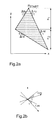
- FIGS. 2a and 2b show such a triangular area to illustrate the division into grid elements.
- the individual raster lines are each parallel to the X axis and equidistant from each other, so that the Y coordinate of all raster elements of a raster line results from the Y coordinate y s of the predetermined corner point P Start and the number i of the raster line.
- the X coordinate x 1 of the starting point of each raster line is obtained accordingly from the X coordinate x s of the specified starting point P start , the number i of the raster line and the edge increment ⁇ lu or ⁇ ld. Within the first n 1 raster lines, the edge increment ⁇ lu and then the edge increment ⁇ ld are used.
- x 1 x s + ⁇ lu ⁇ i
- x 1 x s + ⁇ lu ⁇ n 1 + (in 1 ) ⁇ ⁇ ld
- the X coordinate x r of the end point of each raster line results from the X coordinate x s of the start point P start , the number i of the raster line and the edge increment ⁇ ru or ⁇ rd.
- the assembly 4 thus calculates the for each raster element Polygon area the coordinates X, Y, Z, which requirement for a later interpolation of the color values as well as the Memory matrix addresses within the polygon area.
- the parameter set supplied by the higher-level graphics system is also fed to a further assembly 5 of the computing unit 1, which calculates the local surface normals N 1, N 2, N 3 at the corner points P1, P2, P3 of the triangular polygon surface in order to subsequently determine the color value F1, To be able to calculate F2 or F3 at the corner points according to a local lighting model.
- the coordinates of the corner points P1, P2, P3 calculated by the assembly 6 and the components of the normal vector N 1, N 2 and N 3 determined by the assembly 5 at the corner points P1, P2 and P3 are then fed to a further assembly 7, which calculates the image impression at the three corner points according to a local lighting model.
- the assembly 7 also requires information about the lighting situation and the desired perspective.
- the higher-level graphics system delivers a parameter set E via the system bus 2, which determines the position of a virtual viewer and thus the perspective.
- the assembly 7 receives an illumination data record L for each light source, which represents the position, the main emission direction and the intensity of the light source.
- the corresponding color values for those within the polygon area horizontal grid elements are then dependent from the position of the respective raster element within the polygon area from the color values F1, F2, F3 at the corner points interpolated.
- the assembly 8 is there for everyone of the raster elements has a color value F 'which is by interpolating the for the corner points according to the local lighting model results in determined color values.
- Computing unit 1 simulates a surface structure the polygon area without reducing the polygon area accordingly to have to.
- the desired surface structure is defined by a two-dimensional memory matrix 9, which contains a slope value in each memory location, which by the slope of the local surface normal determines the surface structure and thus a kind of an image contains the surface structure to be simulated.
- Each raster element of the polygon area is identified by a Addressing unit 10 a memory location of the memory matrix 9 and thus assigned an inclination value, being important is that the assignment of the individual grid elements to the associated memory locations of the memory matrix 9 independently of a possible change in position of the polygon area is because the surface structure to be simulated in a Otherwise change of position of the polygon area on the polygon area would hike.
- the addressing unit 10 therefore receives both the coordinates X, Y, Z of the respective raster element as well Texture addresses T1, T2, T3 of the three corner points of the polygon surface and uses it to calculate address values u, v for addressing the two-dimensional memory matrix 9.
- the one for the respective raster element from the memory matrix 9 read inclination value then becomes a module 11 fed therefrom in connection with the above Half-vector at this point another local Color value F "calculated for the respective raster element that reproduces the surface structure to be simulated.
- the color value F 'determined by Gouraud interpolation is then fed together with the color value F "calculated in accordance with the surface structure to a further assembly 12 which, by mixing the two color values F', F", determines the final color value F MIX , which is subsequently stored in a screen memory 13 is written.
- the screen memory 13 contains all of the polygon areas perspective image of the virtual spatial scene. The This image is then reproduced by an input display driver circuit connected to the display memory 13 16 and the screen 14.
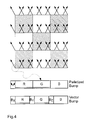
- Figure 4 shows a diagram for explaining a particular Variant of the invention in which the memory matrix (bump map) the local surface normal in each storage location of the respective raster element, so that a Phong shading is possible without the local surface normal Interpolate in the individual grid elements to have to.
- the memory matrix bump map
- the addressing of the memory matrix in Depends on the position of the respective grid element takes place within the polygon area.
- the memory matrix contains in each memory location another texture value for the associated raster element, to add a texture in addition to the deep structure to simulate.
- the invention is not limited in its execution the preferred embodiments given above. Rather, a number of variants are conceivable, which fundamentally different from the solution shown makes use of any type.
Landscapes
- Engineering & Computer Science (AREA)
- Computer Graphics (AREA)
- Physics & Mathematics (AREA)
- General Physics & Mathematics (AREA)
- Theoretical Computer Science (AREA)
- Image Generation (AREA)
Abstract
Vorrichtung bzw. Verfahren zur Darstellung von computermodellierten Objekten, die aus einer Vielzahl von aneinandergrenzenden Polygonflächen zusammengesetzt sind, wobei der Bildeindruck in den Eckpunkten der Polygonflächen entsprechend einem lokalen Beleuchtungsmodell berechnet wird, wohingegen der Bildeindruck der restlichen Rasterelemente entsprechend dem Gouraud-Schattierungsverfahren interpoliert wird und zur Simulation einer Oberflächenstruktur für jedes Rasterelement zusätzlich ein Farb- bzw. Helligkeitswert berechnet wird, der den Einfluß der Oberflächenstruktur auf den Bildeindruck berücksichtigt, ohne in jedem Rasterelement aufwendig das lokale Beleuchtungsmodell berechnen zu müssen. <IMAGE>Device or method for displaying computer-modeled objects which are composed of a plurality of adjoining polygon surfaces, the image impression in the corner points of the polygon surfaces being calculated in accordance with a local lighting model, whereas the image impression of the remaining raster elements is interpolated in accordance with the Gouraud shading method and for Simulation of a surface structure additionally calculates a color or brightness value for each raster element, which takes into account the influence of the surface structure on the image impression, without having to laboriously calculate the local lighting model in each raster element. <IMAGE>
Description
Die Erfindung betrifft ein Verfahren zur Darstellung eines
computermodellierten Objekts gemäß dem Oberbegriff des Anspruchs
1 bzw. 9 sowie eine Vorrichtung zur Durchführung
des Verfahrens gemäß dem Oberbegriff des Anspruchs 6.The invention relates to a method for representing a
computer-modeled object according to the preamble of the
In Computer-Grafiksystemen werden Körper in der Regel durch Gittermodelle nachgebildet, die durch die Raumkoordinaten der Knotenpunkte beschrieben werden. Zur Darstellung der zwischen den Knotenpunkten liegenden Polygonflächen auf einem Bildschirm werden die Raumkoordinaten der Knotenpunkte dann aus dem 3-dimensionalen Koordinatensystem beispielsweise durch Zentralprojektion in ein 2-dimensionales Bildschirm-Koordinatensystem umgerechnet.In computer graphics systems, bodies are usually through Lattice models simulated by the spatial coordinates of the nodes are described. To represent the polygon surfaces between the nodes on a The spatial coordinates of the nodes are displayed on the screen then from the 3-dimensional coordinate system, for example through central projection in a 2-dimensional screen coordinate system converted.
Der Bildeindruck der einzelnen Polygonflächen wird hierbei perspektivisch berechnet, wobei die Position und die Ausrichtung der Polygonfläche relativ zu den Lichtquellen und dem vorgegebenen Betrachterstandort berücksichtigt werden, um einen möglichst natürlichen Bildeindruck zu erreichen.The image impression of the individual polygon surfaces is hereby calculated in perspective, taking position and orientation the polygon area relative to the light sources and the given viewer location are taken into account, in order to achieve a picture impression that is as natural as possible.
Es ist weiterhin bekannt, den Bildeindruck nicht einheitlich jeweils für die gesamte Polygonfläche zu berechnen, sondern die einzelnen Polygonflächen jeweils in eine Vielzahl von Rasterelementen aufzuteilen und den Bildeindruck individuell für jedes Rasterelement zu berechnen, so daß auch mit einem relativ groben Gittermodell mit großen Polygonflächen ein natürlicher Bildeindruck erreicht werden kann. Hierzu werden sogenannte Schattierungsverfahren angewendet, welche die Schattierung - also die Farb- bzw. Helligkeitsabstufung - innerhalb der Polygonfläche berechnen.It is also known that the image impression is not uniform to be calculated for the entire polygon area, but rather the individual polygon areas in a multitude of raster elements and the image impression to be calculated individually for each grid element, so that also with a relatively rough grid model with large polygon areas a natural picture impression can be achieved can. So-called shading processes are used for this, which is the shading - i.e. the color or brightness gradation - calculate within the polygon area.
Ein derartiges Schattierungsverfahren ist als Phong-Schattierung bekannt. Hierbei wird für jede Polygonfläche ein Datensatz vorgegeben, aus dem die lokale Flächennormale an den Eckpunkten der Polygonfläche hervorgeht, so daß auch gekrümmte Polygonflächen realisierbar sind, was den Realitätsgrad der Bilddarstellung weiter verbessert. Für jedes Rasterelement innerhalb der Polygonfläche wird dann aus den vorgegebenen Eckpunktnormalen die lokale Flächennormale interpoliert, die sich aus der Krümmung der Polygonfläche ergibt. Die Berechnung des Bildeindrucks der einzelnen Rasterelemente erfolgt dann unter Berücksichtigung der lokalen Flächennormale entsprechend einem lokalen Beleuchtungsmodell.Such a shading process is called Phong shading known. Here, for each polygon area specified a data set from which the local surface normal at the corner points of the polygon surface, so that also curved polygon surfaces are realizable, which is the degree of reality the image display further improved. For each The grid element within the polygon area is then created from the interpolates the local surface normal to the specified vertex normals, which results from the curvature of the polygon surface. The calculation of the image impression of the individual raster elements then takes place taking into account the local Area normals according to a local lighting model.
Die vorstehend beschriebene Phong-Schattierung ermöglicht zwar durch die Berücksichtigung der Krümmung der einzelnen Polygonflächen vorteilhaft einen sehr natürlichen Bildeindruck, jedoch ist die Berechnung sehr aufwendig, da das lokale Beleuchtungsmodell für jedes Rasterelement berechnet werden muß.The Phong shading described above enables by considering the curvature of the individual Polygon surfaces advantageously a very natural picture impression, however, the calculation is very complex because the local Illumination model calculated for each grid element must become.
Ein Vorteil der Phong-Schattierung ist jedoch in der Möglichkeit zu sehen, eine Oberflächenstruktur der einzelnen Polygonflächen zu simulieren, ohne das Gittermodell entsprechend verfeinern zu müssen. So ist es bei der Darstellung einer Holzoberfläche beispielsweise möglich, die Holzmaserung zu simulieren. Hierzu ist eine zweidimensionale Speichermatrix (engl. Bump Map) vorgesehen, welche die gewünschte Oberflächenstruktur definiert und in jedem Speicherplatz einen Neigungswert enthält, der angibt, wie die lokale Flächennormale aufgrund der Oberflächenstruktur geneigt ist, wobei jedes Rasterelement der Polygonfläche einem Speicherplatz der Speichermatrix zugeordnet ist. Bei der Berechnung des Bildeindrucks der einzelnen Rasterelemente wird also zunächst der zugehörige Speicherplatz der Speichermatrix bestimmt und der Neigungswert ausgelesen, der die Oberflächenstruktur wiedergibt. Bei der Berechnung des Bildeindrucks entsprechend dem lokalen Beleuchtungsmodell wird dann nicht die interpolierte lokale Flächennormale der glatten Polygonfläche berücksichtigt, sondern die entsprechend dem Neigungswert veränderte lokale Flächennormale. Hierbei wird die Tatsache ausgenutzt, daß für den Bildeindruck eines Rasterelements einer tiefenstrukturierten Oberfläche nicht die Position des Rasterelements entscheidend ist, sondern die durch die Oberflächenstruktur verursachte Änderung der lokalen Flächennormale.An advantage of Phong shading, however, is the possibility to see a surface texture of each Simulate polygon surfaces without using the grid model accordingly to have to refine. So it is with the representation a wood surface, for example, the wood grain to simulate. This is a two-dimensional one Storage matrix (English bump map) provided which the desired Surface structure defined and in every storage space contains a slope value that indicates how the local surface normals are inclined due to the surface structure is, with each raster element of the polygon area one Storage space is allocated to the storage matrix. At the calculation of the image impression of the individual raster elements the associated storage space of the Memory matrix determined and the inclination value read out, that reflects the surface structure. At the calculation the image impression according to the local lighting model does not become the interpolated local surface normal the smooth polygon surface, but the local surface normals changed according to the slope value. This takes advantage of the fact that for the Image impression of a raster element of a deeply structured Surface does not determine the position of the grid element but through the surface structure caused change in the local surface normal.
Die vorstehend beschriebene Simulation einer Oberflächenstruktur setzt grundsätzlich jedoch ein Schattierungsverfahren voraus, das die lokale Flächennormale individuell für jedes Rasterelement interpoliert und den Bildeindruck entsprechend einem lokalen Beleuchtungsmodell für jedes Rasterelement berechnet, da die Neigung der lokalen Flächennormale nur bei der Berechnung des lokalen Beleuchtungsmodells berücksichtigt werden kann. Das sogenannte Bump-Mapping ist also bisher nur in Verbindung mit relativ aufwendigen Schattierungsverfahren möglich.The simulation of a surface structure described above however, generally uses a shading method ahead that the local surface normal is individual interpolated for each raster element and the image impression according to a local lighting model for each grid element calculated because the slope of the local surface normal only when calculating the local lighting model can be taken into account. The so-called bump mapping is so far only in connection with relatively complex Shading process possible.
Ein wesentlich einfacheres Schattierungsverfahren ist als Gouraud-Schattierung bekannt. Hierbei wird für jede Polygonfläche ebenfalls ein Datensatz vorgegeben, aus dem die räumliche Lage der lokalen Flächennormalen an den Eckpunkten der Polygonfläche hervorgeht. Im Gegensatz zu der vorstehend beschriebenen Phong-Schattierung erfolgt die Berechnung des lokalen Beleuchtungsmodells hierbei jedoch nur für die Eckpunkte der Polygonfläche, wohingegen der Bildeindruck der innerhalb der Polygonfläche liegenden Rasterelemente in Abhängigkeit von der Position des jeweiligen Rasterelements innerhalb der Polygonfläche aus dem Bildeindruck an den Eckpunkten der Polygonfläche interpoliert wird.A much simpler shading process is than Gouraud shading known. Here, for each polygon area also specified a data set from which the spatial position of the local surface normals at the corner points the polygon surface emerges. In contrast to the previous one Phong shading described, the calculation is made of the local lighting model, however, only for the corner points of the polygon surface, whereas the Image impression of the grid elements lying within the polygon area depending on the position of each Raster elements within the polygon area from the Image impression interpolated at the corner points of the polygon surface becomes.
Einerseits wird hierdurch gegenüber der Phong-Schattierung Rechenzeit gespart, da die aufwendige Berechnung des lokalen Beleuchtungsmodells nur an den Eckpunkten der Polygonfläche erfolgt, während die Interpolation des Bildeindrucks für die einzelnen Rasterelemente bezüglich des Rechenaufwands wesentlich einfacher ist.On the one hand, this contrasts with Phong shading Computation time saved because the complex calculation of the local Illumination model only at the corner points of the polygon surface takes place during the interpolation of the image impression for the individual raster elements in terms of computing effort is much easier.
Andererseits ist der Bildeindruck bei der Gouraud-Schattierung weniger natürlich als bei der aufwendigeren Phong-Schattierung und die Simulation einer Oberflächenstruktur (Bump-Mapping) ist in der vorstehend beschriebenen Weise nicht möglich.On the other hand, the picture impression is with the Gouraud shading less natural than the more complex one Phong shading and the simulation of a surface structure (Bump mapping) is described in the above Way not possible.
Der Erfindung liegt somit die Aufgabe zugrunde, ein Verfahren zur Darstellung computermodellierter Objekte zu schaffen, das bei möglichst geringem Rechenaufwand auch die Simulation einer Oberflächenstruktur ermöglicht, ohne das Gittermodell entsprechend verfeinern zu müssen. Weiterhin liegt der Erfindung die Aufgabe zugrunde, eine entsprechende Vorrichtung zur Durchführung eines derartigen Verfahrens zu schaffen.The invention is therefore based on the object of a method to create computer-modeled objects, the simulation with the least possible computing effort a surface structure without that Need to refine the grid model accordingly. Farther is the object of the invention, a corresponding Device for performing such a method to accomplish.
Die Aufgabe wird, ausgehend von einem Verfahren gemäß dem
Oberbegriff des Anspruchs 1 bzw. 9, durch die im kennzeichnenden
Teil des Anspruchs 1 bzw. 9 angegebenen Merkmale
bzw. - hinsichtlich der Vorrichtung zur Durchführung des
Verfahrens - durch die Merkmale des Anspruchs 6 gelöst.The task is based on a method according to the
Preamble of
Die Erfindung schließt die technische Lehre ein, bei einem Verfahren zur Darstellung computermodellierter Objekte die an sich bekannten Techniken der Gouraud-Schattierung und des sogenannten Bump-Mapping miteinander zu kombinieren.The invention includes the technical teaching in one Process for the representation of computer-modeled objects known techniques of Gouraud shading and the so-called bump mapping.
Die erfinderischen Maßnahmen lassen sich sowohl mit rein softwaremäßigen Maßnahmen als auch mittels geeigneter spezieller Hardware ausführen. Die hardwaremäßige Lösung hat dabei den Vorteil, daß sich insbesondere durch in parallel angeordneten Baugruppen gleichzeitig ausgeführte Operationen große Zeitvorteile erzielen lassen.The inventive measures can be both pure software measures as well as by means of suitable special Run hardware. The hardware solution has the advantage that in particular by parallel arranged assemblies performed operations simultaneously big time savings.
Wenn daher nachfolgend von "Baugruppen" die Rede ist, kann es sich dabei auch um Funktionsgruppen, beispielsweise in Form von elektrischen Schaltungen, handeln. Hierbei ist auch eingeschlossen, daß ein und dieselbe Bau- oder Funktionsgruppe nacheinander unterschiedliche Operationen ausführt, wie es bei der Prozessortechnik allgemein der Fall ist. Geschwindigkeitsvorteile lassen sich aber - wie erläutert - vor allen Dingen dann erzielen, wenn Funktionsgruppen parallel nebeneinander tätig sind.Therefore, when we speak of "assemblies" below, there are also functional groups, for example in Form of electrical circuits, act. Here is also included that one and the same structural or functional group performs different operations one after the other, as is generally the case with processor technology is. However, speed advantages can - as explained - Above all, achieve when functional groups work in parallel.
Die Berechnung des Bildeindrucks erfolgt gemäß der Erfindung durch eine Recheneinheit, die Bestandteil eines übergeordneten Grafiksystems ist und von diesem sämtliche Daten erhält, die zur Berechnung des Bildeindrucks jeweils einer Polygonfläche erforderlich sind.The image impression is calculated in accordance with the invention through a computing unit that is part of a higher-level Graphics system and all of this data receives one to calculate the image impression Polygon area are required.
So erhält die erfindungsgemäße Recheneinheit von dem übergeordneten Grafiksystem einen ersten Parametersatz, der die räumliche Lage der darzustellenden Polygonfläche wiedergibt. Der erste Parametersatz enthält hierzu beispielsweise die Raumkoordinatenwerte der Eckpunkte des darzustellenden Polygons oder die Raumkoordinatenwerte des Flächenschwerpunkts sowie die Komponenten des Normalenvektors der Polygonfläche. Maßgebend für die Zusammensetzung des ersten Parametersatzes ist jedoch lediglich, daß dieser die räumliche Lage der Polygonfläche eindeutig wiedergibt.The computing unit according to the invention thus receives from the parent Graphics system a first parameter set that the reproduces the spatial position of the polygon surface to be displayed. For this purpose, the first parameter set contains, for example the spatial coordinate values of the corner points of the to be displayed Polygons or the spatial coordinate values of the centroid as well as the components of the normal vector of the polygon area. Decisive for the composition of the first parameter set is only that this is the spatial Position of the polygon area clearly shows.
Weiterhin erhält die Recheneinheit einen zweiten Parametersatz, der die Perspektive des Betrachters bestimmt und beispielsweise die Raumkoordinaten des Betrachterstandorts oder die Blickrichtung definiert. Durch eine Änderung dieses zweiten Parametersatzes ist es in einfacher Weise möglich, die Perspektive des Betrachters auf die darzustellenden Objekte zu ändern und so beispielsweise durch eine räumliche Szene "hindurchzuwandern".The computing unit also receives a second parameter set, which determines the perspective of the viewer and for example the spatial coordinates of the viewer's location or defines the viewing direction. By changing this second parameter set, it is possible in a simple manner the viewer's perspective on those to be displayed Change objects and so for example by a "wandering through" the spatial scene.
Darüber hinaus nimmt die Recheneinheit von dem übergeordneten Grafiksystem einen Beleuchtungsdatensatz auf, der die optischen Eigenschaften der Beleuchtung definiert. Vorzugsweise enthält der Beleuchtungsdatensatz die Raumkoordinaten der Lichtquellen sowie deren Abstrahleigenschaften.In addition, the computing unit takes from the parent Graphics system based on a lighting data set that the optical properties of the lighting defined. Preferably the lighting data set contains the spatial coordinates the light sources and their radiation properties.
Aus diesen Daten bestimmt die Recheneinheit dann mittels einer ersten Baugruppe mindestens eine Flächennormale für die jeweilige Polygonfläche, um nachfolgend den Bildeindruck entsprechend einem lokalen Beleuchtungsmodell berechnen zu können. Vorzugsweise berechnet die erste Baugruppe aus dem ersten Parametersatz die lokalen Flächennormalen an sämtlichen Eckpunkten der jeweiligen Polygonfläche.The computing unit then uses this data to determine a first assembly at least one surface normal for the respective polygon area in order to subsequently give the image impression calculate according to a local lighting model to be able to. The first assembly preferably calculates the local surface normals from the first parameter set all corner points of the respective polygon surface.
Anschließend berechnet dann eine zweite Baugruppe der Recheneinheit (engl. Shader) aus dem Beleuchtungsdatensatz, dem ersten Parametersatz und den lokalen Flächennormalen entsprechend einem lokalen Beleuchtungsmodell einen Farbwert, der den Bildeindruck wiedergibt. Vorzugsweise wird das lokale Beleuchtungsmodell für die Eckpunkte der Polygonfläche durchgerechnet, um nachfolgend eine zweidimensionale Interpolation der Farbwerte innerhalb der Polygonfläche durchführen zu können. Der Begriff Farbwert ist hierbei und im folgenden allgemein zu verstehen und nicht auf Chrominanzwerte im engeren Sinne beschränkt, sondern umfaßt bei einer monochromen Darstellung auch reine Luminanzwerte.A second module of the computing unit then calculates (English shader) from the lighting data set, the first parameter set and the local surface normals a color value according to a local lighting model, that reflects the image impression. Preferably the local lighting model for the corner points of the polygon surface calculated to be a two-dimensional one Interpolation of the color values within the polygon area to be able to perform. The term color value is here and in the following to be understood generally and not on chrominance values limited in the narrower sense, but includes a monochrome display also pure luminance values.
Zur Interpolation der Farbwerte entsprechend der Gouraud-Schattierung wird die Polygonfläche mittels einer dritten Baugruppe in eine Vielzahl von Rasterelemente aufgeteilt, wobei für jedes Rasterelement ein Koordinatensatz berechnet wird, der die Position des Rasterelements innerhalb der Polygonfläche angibt.For interpolation of the color values according to the Gouraud shading the polygon surface is created using a third Assembly divided into a plurality of grid elements, where a coordinate set is calculated for each raster element the position of the grid element within the polygon area indicates.
Die eigentliche Interpolation für die Gouraud-Schattierung erfolgt dann individuell für jedes Rasterelement durch eine vierte Baugruppe in Abhängigkeit von der Position des jeweiligen Rasterelements innerhalb der Polygonfläche. Auf diese Weise wird für jedes Rasterelement ein erster lokaler Farbwert berechnet, der jedoch noch keine Oberflächenstruktur berücksichtigt.The actual interpolation for Gouraud shading is then done individually for each raster element fourth assembly depending on the position of each Raster elements within the polygon area. On in this way, a first local one becomes for each raster element Color value calculated, but no surface structure yet considered.
Zur Definition einer Oberflächenstruktur weist die erfindungsgemäße Recheneinheit eine zwei-dimensionale Speichermatrix auf, die in jedem Speicherplatz einen Neigungswert enthält, der die Neigung der lokalen Flächennormale bestimmt, die sich aus der gewünschten Oberflächenstruktur ergibt. Eine vorgegebene Mapping-Funktion beschreibt eine feste Abbildung der Polygoneckpunkte auf die Speichermatrix-Adressen. Jedem Rasterelement der Polygonfläche wird damit in Abhängigkeit von der Position des Rasterelements innerhalb der Polygonfläche ein Speicherplatz der Speichermatrix zugeordnet, dessen Inhalt dann die Neigung der lokalen Flächennormale in diesem Rasterelement bestimmt. The inventive method defines a surface structure Computing unit a two-dimensional memory matrix on that has a slope value in each memory location contains, which determines the slope of the local surface normal, resulting from the desired surface structure results. A given mapping function describes one Fixed mapping of the polygon corner points to the memory matrix addresses. Each raster element of the polygon area is thus depending on the position of the grid element a storage space of the storage matrix within the polygon area assigned, the content of which is then the inclination of the local Surface normal determined in this grid element.
Als Neigungswert kann beispielsweise der Neigungsvektor abgespeichert sein, also der Vektor, der zu der lokalen Flächennormale der glatten Oberfläche addiert werden muß, um den Eindruck der Tiefenstruktur hervorzurufen, oder auch eine "Ersatz"-Flächennormale als solche. Wird diese bereits normiert abgespeichert, vereinfachen sich spätere Winkelberechnungen zur Bestimmung der Beleuchtungsanteile erheblich. Auch ist es möglich, als Neigungswert eine Rotationsmatrix abzuspeichern, die die Drehung der lokalen Flächennormale definiert. Dies ist besonders vorteilhaft, da durch eine Drehung die Länge der lokalen Flächennormale nicht verändert wird.For example, the slope vector can be stored as the slope value be, so the vector that goes to the local surface normal the smooth surface must be added to to give the impression of the deep structure, or also a "replacement" surface normal as such. Will this already saved in a standardized manner, later angle calculations are simplified to determine the lighting components significantly. It is also possible to use a rotation matrix as the inclination value store the rotation of the local surface normal Are defined. This is particularly advantageous because of one turn does not match the length of the local surface normal is changed.
Vorzugsweise wird in der Speichermatrix nicht die Tiefenstruktur selbst als Relief abgespeichert, sondern die sich aus dem Oberflächenverlauf ergebende Neigung der lokalen Flächennormale. Die Berechnung der aufgrund der Tiefenstruktur geneigten lokalen Flächennormale kann deshalb vorteilhaft relativ schnell und mit geringem Rechenaufwand erfolgen.The depth structure is preferably not in the memory matrix itself saved as a relief, but the itself inclination of the local resulting from the surface course Surface normal. The calculation of the due to the deep structure inclined local surface normal can therefore be advantageous done relatively quickly and with little computation.
Entscheidend ist in diesem Zusammenhang, daß der Tiefenwert ausschließlich von der Position des Rasterelements innerhalb der Polygonfläche abhängt, nicht jedoch von der globalen Position des Rasterelements oder der räumlichen Lage der Polygonfläche. Dies ist notwendig, da andernfalls die auf der Polygonoberfläche erscheinende Tiefenstruktur bei einer Bewegung des Polygons auf der Oberfläche "wandern" würde. Die Adressierung der Speichermatrix erfolgt deshalb individuell für jedes Rasterelement in Abhängigkeit von dem jeweiligen Koordinatensatz, wobei die Adressierungseinheit sicherstellt, daß die Zuordnung der einzelnen Rasterelemente zu den Speicherplätzen der Speichermatrix unabhängig von einer eventuellen Positionsänderung der Polygonfläche ist. It is crucial in this context that the depth value exclusively from the position of the grid element within depends on the polygon area, but not on the global one Position of the grid element or the spatial position the polygon area. This is necessary because otherwise the depth structure appearing on the polygon surface "move" a movement of the polygon on the surface would. The memory matrix is therefore addressed individually for each grid element depending on the respective set of coordinates, the addressing unit ensures that the assignment of the individual grid elements to the memory locations of the memory matrix regardless of a possible change in position of the polygon area.
Die eigentliche Berücksichtigung der durch die Speichermatrix definierten Oberflächenstruktur erfolgt dann durch eine fünfte Baugruppe der Recheneinheit, die den Neigungswert des jeweiligen Rasterelements aus der Speichermatrix ausliest und in Verbindung mit einem die Beleuchtungssituation widerspiegelnden Vektor, der die Information über die Beziehung zwischen Augpunkt und Lichtquelle enthält, einen zweiten lokalen Farbwert berechnet, der die Oberflächenstruktur berücksichtigt.The actual consideration of the through the memory matrix defined surface structure is then carried out by a fifth assembly of the arithmetic unit, the inclination value reads the respective raster element from the memory matrix and in connection with one the lighting situation reflecting vector that represents the information about the relationship contains between the eye point and the light source second local color value calculated that the surface structure considered.
Der die Beleuchtungssituation widerspiegelnde Vektor - etwa der sogenannte Halbvektor - muß als zusätzliche Information zur Verfügung stehen (in der beschriebenen Version lx je Polygon), vorberechnet, in das Bump-Koordinatensystem transformiert sein und übergeben werden. Bei der Berechnung des Beleuchtungsmodells an den Polygonecken für die Gouraud-Schattierung wird ein solcher Vektor bereits benötigt und berechnet; bei Verwendung einer anderen Beleuchtungsgleichung ist ein adäquater Vektor erforderlich.The vector reflecting the lighting situation - for example the so-called half-vector - must be used as additional information are available (in the described version lx each Polygon), precalculated, into the bump coordinate system be transformed and handed over. At the calculation of the lighting model on the polygon corners for Gouraud shading such a vector is already required and calculated; when using a different lighting equation an adequate vector is required.
Mit der Transformation des Halbvektors in das Bump-Koordinatensystem wird die Lage des Polygons im Raum "versteckt", und der transformierte Halbvektor enthält die gesamte Information zur Ausführung eines "bump-mapping".With the transformation of the half-vector into the bump coordinate system the position of the polygon in space "hidden" and the transformed half-vector contains the all information for the execution of a "bump mapping".
Diese Vorgehensweise umgeht eine aufwendige Transformation
jedes einzelnen Speichermatrixelements ins Beleuchtungskoordinatensystem,
nach Ausführung nur einer Transformation
je Polygon kann der lokale zweite Farbwert im Bump-Koordinatensystem
berechnet werden. Die Beleuchtung werde
in einem bestimmten Koordinatensystem, bezeichnet als Weltsystem
(WC), berechnet. Das zu betrachtende Objekt werde in
einem geeigneten Modell-Koordinatensystem (MC) beschrieben.
Das Koordinatensystem der Einträge der Speichermatrix sei
bezeichnet als Texture Bump-System (TB). Eine Matrix M
(mapping matrix) beschreibt die Abbildung eines Vektors v
des TB nach MC (gegeben bzw. zu ermitteln aus der Zuordnung
Objektpunkte Bump-Adressen). Eine Matrix P (model matrix)
beschreibt die Abbildung eines Vektors v des MC nach
WC. Der Halbvektor sei H.
Die Berechnung des endgültigen lokalen Farbwerts für die nachfolgende Ansteuerung eines Bildschirms oder einer anderen Ausgabeeinheit erfolgt dann durch Mischung des ersten und des zweiten lokalen Farbwerts mittels einer sechsten Baugruppe.The calculation of the final local color value for the subsequent control of a screen or another The output unit is then made by mixing the first and the second local color value by means of a sixth Assembly.
Die Erfindung ermöglicht also erstmals die Simulation einer Oberflächenstruktur in Verbindung mit einem einfachen Schattierungs-Algorithmus vom Goraud-Typ, so daß auch bei schnellen Bewegtbilddarstellungen aufgrund der Ersparnis an Rechenzeit eine Oberflächenstruktur darstellbar ist.The invention thus enables the simulation of a Surface structure combined with a simple Goraud-type shading algorithm, so that even with fast moving images because of the savings Computing time a surface structure can be represented.
In einer vorteilhaften Variante der Erfindung von eigener schutzwürdiger Bedeutung enthält die Speichermatrix direkt die lokale Flächennormale in dem jeweiligen Rasterelement. Im Gegensatz zu den herkömmlichen Verfahren des Bump-Mapping ist hierbei also keine rechenaufwendige Interpolation der lokalen Flächennormale während der Darstellung erforderlich, da die Speichermatrix (Bump-Map) direkt die lokale Flächennormale enthält. Zur Bestimmung der lokalen Flächennormale in dem jeweiligen Rasterelement ist es also lediglich erforderlich, aus dem Koordinatensatz des Rasterelements den zugehörigen Speicherplatz der Speichermatrix zu bestimmen und die Speichermatrix entsprechend zu adressieren, so daß die lokale Flächennormale ausgelesen werden kann.In an advantageous variant of the invention of its own The memory matrix contains protection-worthy meaning directly the local surface normal in the respective grid element. In contrast to the conventional methods of bump mapping is not a computationally complex interpolation the local surface normal required during the display, since the storage matrix (bump map) directly the local one Contains surface normal. To determine the local So it is surface normal in the respective grid element only required from the coordinate set of the grid element the associated storage space of the storage matrix to determine and address the memory matrix accordingly, so that the local surface normal can be read out can.
In einer Ausführungsform dieser Variante erfolgt die Berechnung der lokalen Farbwerte für die einzelnen Rasterelemente dann entsprechend dem bereits eingangs beschriebenen Phong'schen Schattierungsverfahren, was wegen der schnellen Berechnung der lokalen Flächennormale ohne eine zeitaufwendige Interpolation aus den Eckpunktnormalen in vertretbarer Rechenzeit möglich ist.In one embodiment of this variant, the calculation is carried out the local color values for the individual raster elements then according to the one already described at the beginning Phong shading method, which is because of the fast Calculation of the local surface normal without a time consuming Interpolation from the vertex normals in a reasonable way Computing time is possible.
In einer anderen Ausführungsform dieser Variante erfolgt die Berechnung der lokalen Farbwerte für die einzelnen Rasterelemente dagegen zunächst - wie bereits vorstehend beschrieben - entsprechend dem Gouraud-Schattierungsverfahren durch Interpolation der für die Eckpunkte aus dem lokalen Beleuchtungsmodell berechneten Farbwerte, während die aus der Speichermatrix ausgelesenen lokalen Flächennormalen lediglich zur nachträglichen Hinzufügung von Phong'schen Beleuchtungsanteilen dienen.In another embodiment of this variant the calculation of the local color values for the individual raster elements on the other hand - as already described above - according to the Gouraud shading method by interpolating the for the corner points from the local Lighting model calculated color values while the off local surface normals read from the memory matrix only for the subsequent addition of Phong lighting components to serve.
Gemäß einer weiteren Ausführungsform dieser Variante dient die aus der Speichermatrix ausgelesene lokale Flächennormale dagegen zur Adressierung einer weiteren Speichermatrix (engl. Reflection Map), die eine Hüllfläche um das jeweilige Rasterelement nachbildet. Derartige Reflection Maps sind dem Fachmann bekannt, wobei die Adressierung der Reflection Map bei Annahme spekularer Reflexion durch den reflektierten Augvektor erfolgt, wohingegen bei diffuser Reflexion die lokale Flächennormale die Reflection- bzw. Environment-Map direkt adressiert. According to a further embodiment of this variant the local surface normal read from the memory matrix on the other hand, for addressing a further memory matrix (English Reflection Map), which is an envelope around the respective Replicates raster element. Such reflection maps are known to the person skilled in the art, the addressing of the reflection Map assuming specular reflection by the reflected Eye vector occurs, whereas with diffuse reflection the local surface normal is the reflection or environment map addressed directly.
Darüber hinaus bietet die vorstehend beschriebene schnelle Bestimmung der lokalen Flächennormale auch die Möglichkeit einer Anwendung von Raytracing-Verfahren.In addition, the one described above offers quick Determination of the local surface normals also the possibility an application of ray tracing methods.
Der Körper bzw. die Fläche, die auf dem Bildschirm dargestellt werden soll, wird - wie bereits vorstehend beschrieben - im Computer als Gittermodell nachgebildet. Die Oberfläche besteht deshalb aus zahlreichen Polygonflächen, deren räumliche Lage durch die Raumkoordinaten der Knotenpunkte des Gittermodells definiert ist. Vorzugsweise werden als Polygonflächen Dreiecke verwendet, was den Vorteil bietet, daß die Flächennormale eines Dreiecks durch die Raumkoordinaten der Eckpunkte eindeutig definiert ist, da drei Punkte immer in einer Ebene liegen, während bei Polygonen mit mehr als drei Eckpunkten die Möglichkeit besteht, daß die Eckpunkte nicht exakt in einer Ebene liegen, so daß auch die Flächennormale nicht exakt definiert ist.The body or area shown on the screen should be - as already described above - reproduced in the computer as a grid model. The surface therefore consists of numerous polygon surfaces whose spatial position through the spatial coordinates of the nodes of the grid model is defined. Preferably be uses triangles as polygon surfaces, which has the advantage that the surface normal of a triangle through the spatial coordinates the key points are clearly defined as three Points always lie in one plane, while with polygons with more than three corner points there is a possibility that the corner points are not exactly in one plane, so that the surface normal is also not exactly defined.
Das vorstehend beschriebene Verfahren ist nicht beschränkt auf eine monochrome Darstellung. Vielmehr kann das Verfahren nacheinander oder parallel für mehrere Farben - vorzugsweise die Grundfarben - durchgeführt werden. Hierbei kann auch ein farbabhängiges Reflexions- oder Absorptionsverhalten der Oberfläche berücksichtigt werden.The method described above is not limited on a monochrome display. Rather, the process successively or in parallel for several colors - preferably the primary colors - are carried out. Here can also have a color-dependent reflection or absorption behavior the surface are taken into account.
In einer vorteilhaften Variante der Erfindung ist die Vorrichtung als integrierte Schaltung in einem Prozessorsystem oder auch als selbständiger Prozessor ausgeführt, die an ihrem Eingang einen Parametersatz aufnimmt, der unter anderem die räumliche Lage einer Polygonfläche bestimmt. Am Ausgang werden dann die Bildschirmkoordinaten einzelner Rasterelemente der Polygonfläche sowie der Helligkeitswert der Rasterelemente ausgegeben. Die Schaltung läßt sich somit günstig in bestehende Computer-Grafiksysteme einbinden. The device is in an advantageous variant of the invention as an integrated circuit in a processor system or also run as a stand-alone processor, the on records a parameter set at its input, which among other things determines the spatial position of a polygon surface. At the The screen coordinates of individual grid elements then become the output the polygon area and the brightness value of the raster elements. The circuit can thus be cheaply integrate into existing computer graphics systems.
Andere vorteilhafte Weiterbildungen der Erfindung sind in den Unteransprüchen gekennzeichnet bzw. werden nachstehend zusammen mit der Beschreibung der bevorzugten Ausführung der Erfindung anhand der Figuren näher dargestellt. Es zeigen:
Figur 1- als bevorzugtes Ausführungsbeispiel der Erfindung eine Recheneinheit zur Darstellung von computermodellierten Objekten als Bestandteil eines umfassenden Computer-Grafiksystems,
- Figur 2a, 2b
- ein Schema zur Erläuterung der Aufteilung der Polygonflächen in Rasterelemente,
Figur 3- eine schematische Darstellung der Beleuchtungssituation zur Veranschaulichung des lokalen Beleuchtungsmodells sowie
- Figur 4
- ein Schema zur Verdeutlichung der Aufprägung eines Vektorfeldes und einer Textur auf eine Polygonfläche.
- Figure 1
- as a preferred embodiment of the invention, a computing unit for displaying computer-modeled objects as part of a comprehensive computer graphics system,
- Figure 2a, 2b
- a diagram to explain the division of the polygon areas into grid elements,
- Figure 3
- a schematic representation of the lighting situation to illustrate the local lighting model and
- Figure 4
- a scheme to illustrate the imprint of a vector field and a texture on a polygon surface.
Figur 1 zeigt eine Recheneinheit 1, die eine Darstellung
von computer-modellierten Objekten ermöglicht und Bestandteil
eines umfassenden Computer-Grafiksystems ist, von dem
hier lediglich ein Systembus 2 dargestellt ist. Die einzelnen
Objekte sind hierbei in dem Grafiksystem als Gittermodell
gespeichert und durch die Raumkoordinaten der Knotenpunkte
des Gittermodells sowie durch die optischen Eigenschaften
der zwischen den Knotenpunkten liegenden dreieckigen
Polygonflächen - beispielsweise die Farbe und die Reflexionseigenschaften
- definiert. Figure 1 shows a
Die dargestellte Recheneinheit 1 berechnet nacheinander den
Bildeindruck sämtlicher Polygonflächen der einzelnen Objekte,
wobei die räumliche Lage der jeweiligen Polygonfläche,
die gewünschte Perspektive sowie die Beleuchtungssituation
von dem Grafiksystem über den Systembus 2 vorgegeben werden.
Die Recheneinheit 1 erhält hierzu von dem Grafiksystem
über den Systembus 2 für jede darzustellende Polygonfläche
einen Parametersatz, der die räumliche Lage sowie die optischen
Eigenschaften der jeweiligen Polygonfläche wiedergibt
und eine Feinaufteilung der Polygonfläche in eine Vielzahl
von Rasterelementen ermöglicht, die jeweils in Rasterzeilen
angeordnet sind. So enthält der Parametersatz die Raumkoordinaten
(xs , ys , zs ) eines Eckpunkts Pstart des Dreiecks, die
Kanteninkremente Δlu, Δru, Δld, Δrd, die Anzahl der Rasterzeilen
n1 , n2 des Dreiecks, sowie die Neigung Δzx der Dreiecksfläche
zur X-Achse und die Neigung Δzy der Dreiecksfläche
zur Y-Achse. Darüber hinaus enthält der Parametersatz
die Koordinaten der lokalen Flächennormale N Start in dem
vorgegeben Eckpunkt sowie die Vektorinkremente Δ N x , Δ N y ,
die eine Berechnung der lokalen Flächennormale in jedem Rasterelement
der Dreiecksfläche ermöglichen. Die Dreiecksfläche
ist also nicht notwendigerweise eben, sondern in der
Regel gekrümmt, und ihre Krümmung wird - nur für die Beleuchtung
- durch eine Flächennormaleninterpolation simuliert.
Zum einen ermöglicht dies eine Anpassung der Krümmung
an einen vorgegebenen Oberfächenverlauf der Objekte.
Zum anderen ist es auf diese Weise möglich, an den Kanten
zwischen benachbarten Dreiecksflächen einen knickfreien und
damit optisch unauffälligen Übergang zu erreichen. Der Parametersatz
enthält ferner die Bumptextur-Koordinaten
uStart, vStart sowie die zugehörigen Inkremente dux, dvx, duy,
dvy, die eine Berechnung der lokalen Speichermatrixadresse
in jedem Rasterelement der Dreiecksfläche ermöglichen. Weiterhin
enthält der Parametersatz Informationen über die
Farbe der Dreiecksoberfläche, das Absorptionsverhalten, die
Durchsichtigkeit der Dreiecksfläche und ähnliches.The illustrated
Der von dem übergeordneten Grafiksystem gelieferte Parametersatz
wird in der Recheneinheit 1 unter anderem einer
Baugruppe 3 (engl. Scanline Initializer) zugeführt, die die
Dreiecksfläche zunächst in eine Vielzahl von Rasterzeilen
aufteilt und für jede Rasterzeile die Raumkoordinaten des
Anfangspunkts (x1 , y1 , z1 ) und des Endpunkts (xr, yr, zr) berechnet.
Die Figuren 2a und 2b zeigen eine derartige Dreiecksfläche
zur Veranschaulichung der Aufteilung in Rasterelemente.
Die einzelnen Rasterzeilen liegen jeweils parallel
zur X-Achse und äquidistant zueinander, so daß sich die
Y-Koordinate sämtlicher Rasterelemente einer Rasterzeile
aus der Y-Koordinate ys des vorgegebenen Eckpunkts PStart und
der Nummer i der Rasterzeile ergibt. Für die Y-Koordinaten
von Anfangspunkt und Endpunkt der einzelnen Raster zeilen
gilt also:
Die X-Koordinate x1 des Anfangspunkts jeder Rasterzeile ergibt
sich entsprechend aus der X-Koordinate xs des vorgegebenen
Startpunkts Pstart, der Nummer i der Rasterzeile sowie
dem Kanteninkrement Δlu bzw. Δld. Innerhalb der ersten n1
Rasterzeilen wird hierbei das Kanteninkrement Δlu und anschließend
das Kanteninkrement Δld verwendet.
In gleicher Weise ergibt sich die X-Koordinate xr des Endpunkts
jeder Rasterzeile aus der X-Koordinate xs des Startpunkts
Pstart , der Nummer i der Rasterzeile sowie dem Kanteninkrement
Δru bzw. Δrd. Hierbei wird während der ersten
n1 Rasterzeilen das Kanteninkrement Δru und anschließend
das Kanteninkrement Δrd verwendet:
Die Z-Koordinate z1 des Anfangspunkts jeder Rasterzeile ergibt
sich aus der Z-Koordinate zs des Startpunkts Pstart, der
Nummer i der Rasterzeile sowie den vorgegebenen Neigungen
der Dreiecksfläche zur X-Achse und zur Y-Achse:
Die Baugruppe 3 gibt dann den vorgegebenen Neigungswert Δzy
der Dreiecksfläche sowie die Koordinaten von Anfangspunkt
(x1, y1, z1) und Endpunkt (xr, yr, zr) jeweils einer Rasterzeile
an eine nachgeschaltete Baugruppe 4 (engl. PCC - Pixel
Coordinate Calculator), die die einzelnen Rasterzeilen
in eine Vielzahl von Rasterelementen aufteilt und deren Koordinaten
berechnet. Da die Rasterzeilen parallel zur X-Achse
verlaufen, ist die Y-Koordinate jedes Rasterelements
gleich der Y-Koordinate der zugehörigen Rasterzeile:
Die X-Koordinate jedes Rasterelements ergibt sich aus der
X-Koordinate x1 des Anfangspunkts der Rasterzeile, und der
Nummer j des Rasterelements in der Rasterzeile:
Die Z-Koordinate eines Rasterelements läßt sich in einfacher
Weise aus der Z-Koordinate z1 des Anfangspunkts der
zugehörigen Rasterzeile, der Nummer j des Rasterelements
innerhalb der Rasterzeile und der Neigung Δzx der Dreiecksfläche
relativ zur X-Achse berechnen:
Die Baugruppe 4 berechnet also für jedes Rasterelement der Polygonfläche die Koordinaten X, Y, Z, was Voraussetzung für eine spätere Interpolation der Farbwerte sowie der Speichermatrixadressen innerhalb der Polygonfläche ist.The assembly 4 thus calculates the for each raster element Polygon area the coordinates X, Y, Z, which requirement for a later interpolation of the color values as well as the Memory matrix addresses within the polygon area.
Der von dem übergeordneten Grafiksystem gelieferte Parametersatz
wird darüber hinaus einer weiteren Baugruppe 5 der
Recheneinheit 1 zugeführt, welche die lokalen Flächennormalen
N1, N2, N3 an den Eckpunkten P1, P2, P3 der dreieckigen
Polygonfläche berechnet, um nachfolgend den Farbwert F1, F2
bzw. F3 an den Eckpunkten entsprechend einem lokalen Beleuchtungsmodell
berechnen zu können.The parameter set supplied by the higher-level graphics system is also fed to a
Darüber hinaus wird der von dem übergeordneten Grafiksystem
gelieferte Parametersatz eine weiteren Baugruppe 6 zugeführt,
die die Koordinaten der drei Eckpunkte P1, P2, P3
der dreieckigen Polygonfläche berechnet.In addition, that of the parent graphics system
supplied parameter set supplied to another
Die von der Baugruppe 6 berechneten Koordinaten der Eckpunkte
P1, P2, P3 sowie die von der Baugruppe 5 ermittelten
Komponenten des Normalenvektors N1, N2 bzw. N3 an den Eckpunkten
P1, P2 bzw. P3 werden dann einer weiteren Baugruppe
7 zugeführt, die den Bildeindruck an den drei Eckpunkten
entsprechend einem lokalen Beleuchtungsmodell berechnet.
Neben der Information über die räumliche Position und die
Flächennormale in den Eckpunkten benötigt die Baugruppe 7
hierzu Informationen über die Beleuchtungssituation sowie
über die gewünschte Perspektive. Das übergeordnete Grafiksystem
liefert hierzu über den Systembus 2 einen Parametersatz
E, der die Position eines virtuellen Betrachters und
damit die Perspektive bestimmt. darüber hinaus erhält die
Baugruppe 7 für jede Lichtquelle einen Beleuchtungsdatensatz
L, der die Position die Hauptabstrahlrichtung und die
Intensität der Lichtquelle wiedergibt.The coordinates of the corner points P1, P2, P3 calculated by the
Die Berechnung des Bildeindrucks am jeweiligen Eckpunkt erfolgt
dann getrennt für die drei Grundfarben Rot, Grün und
Blau des RGB-Farbmodells entsprechend dem in Figur 3 schematisch
dargestellten lokalen Beleuchtungsmodell nach der
Formel:


- acm, dcm, Scm
- ambiente, diffuse bzw. spekulare Farbe des Materials
- ecm
- emissive Farbe des Materials
- Srm
- spekularer Exponent des Materials
- acli, dcli, Scli
- ambiente, diffuse bzw. spekulare Farbe von Lichtquelle i
- Ppli
- Position von Lichtquelle i
- Sdli
- Hauptabstrahlrichtung von Lichtquelle i
- Srli
- Spotlight-Exponent von Lichtquelle i
- Crli
- Spotlight-Cutoff-Winkel von Lichtquelle i
- k0i, k1i, k2i
- konstante, lineare und quadratische Entfernungsabschwächung von Lichtquelle i
- acs
- ambiente Farbe der Szene
- a cm , d cm , S cm
- ambient, diffuse or specular color of the material
- e cm
- emissive color of the material
- S rm
- specular exponent of the material
- a cli , d cli , S cli
- ambient, diffuse or specular color of light source i
- P pli
- Position of light source i
- S dli
- Main emission direction of light source i
- S rli
- Spotlight exponent from light source i
- C rli
- Spotlight cutoff angle from light source i
- k 0i , k 1i , k 2i
- constant, linear and quadratic distance attenuation of light source i
- a cs
- ambient color of the scene
Am Ausgang der Baugruppe 7 erscheint somit für jeden der
drei Eckpunkte jeweils ein Farbwert F1, F2 bzw. F3, der die
Intensität der drei Grundfarben für diesen Eckpunkt wiedergibt.At the output of
Die entsprechenden Farbwerte für die innerhalb der Polygonfläche
liegenden Rasterelemente werden dann in Abhängigkeit
von der Position des jeweiligen Rasterelements innerhalb
der Polygonfläche aus den Farbwerten F1, F2, F3 an den Eckpunkten
interpoliert. Hierzu ist eine weitere Baugruppe 8
vorgesehen, die zur Aufnahme der für die Eckpunkte ermittelten
Farbwerte F1, F2, F3 mit der Baugruppe 7 verbunden
ist und die Koordinaten des jeweiligen Rasterelements von
der Baugruppe 4 aufnimmt. Die Baugruppe 8 gibt also für jedes
der Rasterelemente einen Farbwert F' aus, der sich
durch Interpolation der für die Eckpunkte entsprechend dem
lokalen Beleuchtungsmodell ermittelten Farbwerte ergibt.The corresponding color values for those within the polygon area
horizontal grid elements are then dependent
from the position of the respective raster element within
the polygon area from the color values F1, F2, F3 at the corner points
interpolated. There is a
Darüber hinaus ermöglicht die dargestellte erfindungsgemäße
Recheneinheit 1 die Simulation einer Oberflächenstruktur
der Polygonfläche, ohne die Polygonfläche entsprechend verkleinern
zu müssen. Die gewünschte Oberflächenstruktur wird
hierbei durch eine zwei-dimensionale Speichermatrix 9 definiert,
die in jedem Speicherplatz einen Neigungswert enthält,
der die Neigung der lokalen Oberflächennormale durch
die Oberflächenstruktur bestimmt und somit quasi ein Abbild
der zu simulierenden Oberflächenstruktur enthält.In addition, the illustrated enables
Der vom übergeordneten Grafiksystem gelieferte Parametersatz
wird hierzu einer weiteren Baugruppe 17 zugeführt,
die die Speichermatrixadressen T1 = (u1, v1), T2 = (u2,
v2), T3 = (u3, v3) der drei Eckpunkte der dreieckigen Polygonfläche
berechnet.The parameter set supplied by the higher-level graphics system
is fed to a
Jedem Rasterelement der Polygonfläche wird durch eine
Adressierungseinheit 10 ein Speicherplatz der Speichermatrix
9 und damit ein Neigungswert zugeordnet, wobei wichtig
ist, daß die Zuordnung der einzelnen Rasterelemente zu den
zugehörigen Speicherplätzen der Speichermatrix 9 unabhängig
von einer eventuellen Positionsänderung der Polygonfläche
ist, da die zu simulierende Oberflächenstruktur bei einer
Positionsänderung der Polygonfläche andernfalls auf der Polygonfläche
wandern würde.Each raster element of the polygon area is identified by a
Addressing unit 10 a memory location of the
Die Adressierungseinheit 10 erhält deshalb sowohl die Koordinaten
X, Y, Z des jeweiligen Rasterelements als auch die
Texturadressen T1, T2, T3 der drei Eckpunkte der Polygonfläche
und berechnet daraus Adreßwerte u, v für die Adressierung
der zwei-dimensionalen Speichermatrix 9.The addressing
Der für das jeweilige Rasterelement aus der Speichermatrix
9 ausgelesene Neigungswert wird dann einer Baugruppe
11 zugeführt, die daraus in Verbindung mit dem oben erwähnten
Halbvektor an dieser Stelle einen weiteren lokalen
Farbwert F" für das jeweilige Rasterelement berechnet, der
die zu simulierende Oberflächenstruktur wiedergibt.The one for the respective raster element from the
Der durch Gouraud-Interpolation ermittelte Farbwert F' wird
dann zusammen mit dem entsprechend der Oberflächenstruktur
berechneten Farbwert F" einer weiteren Baugruppe 12 zugeführt,
die durch Mischung der beiden Farbwerte F', F" den
endgültigen Farbwert FMIX bestimmt, der nachfolgend in einen
Bildschirmspeicher 13 geschrieben wird.The color value F 'determined by Gouraud interpolation is then fed together with the color value F "calculated in accordance with the surface structure to a
Zur Darstellung auf einem Bildschirm 14 ist es weiterhin
erforderlich, die dreidimensionalen Koordinaten X, Y, Zder
einzelnen Rasterelemente in ein zweidimensionales Bildschirm-Koordinatensystem
umzurechnen, das die Position des
jeweiligen Rasterelements auf dem Bildschirm 14 angibt. Die
von der Baugruppe 4 berechneten Koordinaten X, Y, Z werden
deshalb einer auch als Z-Filter bezeichneten Baugruppe 15
zugeführt, die nach Z-Werten sichtbare und unsichtbare
Punkte aussortiert.It is still for display on a
Nach der Berechnung der Farbwerte sämtlicher Rasterelemente
aller Polygonflächen enthält der Bildschirmspeicher 13 ein
perspektivisches Bild der virtuellen räumlichen Szene. Die
Wiedergabe dieses Bildes erfolgt dann durch eine eingangsseitig
mit dem Bildschirmspeicher 13 verbundene Bildschirmtreiberschaltung
16 und den Bildschirm 14.After calculating the color values of all grid elements
The
Figur 4 zeigt ein Schema zur Erläuterung einer besonderen Variante der Erfindung, bei der die Speichermatrix (Bump-Map) in jedem Speicherplatz direkt die lokale Flächennormale des jeweiligen Rasterelements enthält, so daß eine Phong-Schattierung möglich ist, ohne die lokale Flächennormale in den einzelnen Rasterelementen aufwendig interpolieren zu müssen. Zur Bestimmung der lokalen Flächennormale ist also lediglich ein Lesezugriff auf die Speichermatrix erforderlich, wobei die Adressierung der Speichermatrix in Abhängigkeit von der Position des jeweiligen Rasterelements innerhalb der Polygonfläche erfolgt. Figure 4 shows a diagram for explaining a particular Variant of the invention in which the memory matrix (bump map) the local surface normal in each storage location of the respective raster element, so that a Phong shading is possible without the local surface normal Interpolate in the individual grid elements to have to. To determine the local surface normal is therefore only read access to the memory matrix required, the addressing of the memory matrix in Depends on the position of the respective grid element takes place within the polygon area.
Darüber hinaus enthält die Speichermatrix in jedem Speicherplatz noch einen Texurwert für das zugehörige Rasterelement, um zusätzlich zu der Tiefenstruktur auch eine Textur zu simulieren.In addition, the memory matrix contains in each memory location another texture value for the associated raster element, to add a texture in addition to the deep structure to simulate.
Die Erfindung beschränkt sich in ihrer Ausführung nicht auf die vorstehend angegebenen bevorzugten Ausführungsbeispiele. Vielmehr ist eine Anzahl von Varianten denkbar, welche von der dargestellten Lösung auch bei grundsätzlich anders gearteten Ausführungen Gebrauch macht.The invention is not limited in its execution the preferred embodiments given above. Rather, a number of variants are conceivable, which fundamentally different from the solution shown makes use of any type.
Claims (11)
Applications Claiming Priority (4)
| Application Number | Priority Date | Filing Date | Title |
|---|---|---|---|
| DE19712076 | 1997-03-11 | ||
| DE19712076 | 1997-03-11 | ||
| DE19713466A DE19713466A1 (en) | 1997-03-11 | 1997-03-20 | Method and device for displaying computer-modeled objects |
| DE19713466 | 1997-03-20 |
Publications (3)
| Publication Number | Publication Date |
|---|---|
| EP0865002A2 true EP0865002A2 (en) | 1998-09-16 |
| EP0865002A3 EP0865002A3 (en) | 1999-03-10 |
| EP0865002B1 EP0865002B1 (en) | 2004-03-31 |
Family
ID=26035136
Family Applications (1)
| Application Number | Title | Priority Date | Filing Date |
|---|---|---|---|
| EP98250088A Expired - Lifetime EP0865002B1 (en) | 1997-03-11 | 1998-03-09 | Method and device for displaying computer modelled objects |
Country Status (2)
| Country | Link |
|---|---|
| US (1) | US6429872B1 (en) |
| EP (1) | EP0865002B1 (en) |
Families Citing this family (8)
| Publication number | Priority date | Publication date | Assignee | Title |
|---|---|---|---|---|
| US6593925B1 (en) * | 2000-06-22 | 2003-07-15 | Microsoft Corporation | Parameterized animation compression methods and arrangements |
| US6828980B1 (en) * | 2000-10-02 | 2004-12-07 | Nvidia Corporation | System, method and computer program product for z-texture mapping |
| US6639594B2 (en) * | 2001-06-03 | 2003-10-28 | Microsoft Corporation | View-dependent image synthesis |
| US7865041B1 (en) * | 2001-08-09 | 2011-01-04 | Pixelworks, Inc. | Artifacts measurement on video decomposable properties by dynamic fuzzy reasoning |
| TW550520B (en) * | 2002-03-07 | 2003-09-01 | Ulead Systems Inc | Method for forming bump effect on 3D object in computer graphics |
| JP4220182B2 (en) * | 2002-05-31 | 2009-02-04 | 株式会社東芝 | High-dimensional texture drawing apparatus, high-dimensional texture compression apparatus, high-dimensional texture drawing system, high-dimensional texture drawing method and program |
| US9965893B2 (en) * | 2013-06-25 | 2018-05-08 | Google Llc. | Curvature-driven normal interpolation for shading applications |
| CN113112600B (en) * | 2021-04-02 | 2023-03-03 | 浙江大学 | Structure-Based 3D Modeling Method for Indoor Scenes |
Family Cites Families (1)
| Publication number | Priority date | Publication date | Assignee | Title |
|---|---|---|---|---|
| DE19606356A1 (en) * | 1995-08-25 | 1997-02-27 | Gmd Gmbh | Image processing method for simulating a deep structure and associated device |
-
1998
- 1998-03-09 EP EP98250088A patent/EP0865002B1/en not_active Expired - Lifetime
- 1998-03-11 US US09/038,049 patent/US6429872B1/en not_active Expired - Fee Related
Also Published As
| Publication number | Publication date |
|---|---|
| EP0865002B1 (en) | 2004-03-31 |
| US6429872B1 (en) | 2002-08-06 |
| EP0865002A3 (en) | 1999-03-10 |
Similar Documents
| Publication | Publication Date | Title |
|---|---|---|
| EP0862141A2 (en) | Image presentation method and apparatus | |
| DE3855231T2 (en) | Priority resolution system between polygons with anti-aliasing | |
| EP0984397B1 (en) | Method and device for elimination of unwanted steps in raster displays | |
| EP0789328B1 (en) | Picture processing method for displaying reflective objects and device therefor | |
| DE69127915T2 (en) | Priority color mapping system and method | |
| DE68927471T2 (en) | Process for shading a graphic image | |
| DE3854543T2 (en) | Priority management of a depth data buffer for real-time computer systems for image generation. | |
| DE10296401B4 (en) | Composite rendering of 3-D graphics objects | |
| DE69328464T2 (en) | Method of calculating the lighting for data of three-dimensional objects | |
| DE60120474T2 (en) | GRINDING OF THREE-DIMENSIONAL PICTURES | |
| DE69602728T2 (en) | DEVICE FOR IMAGE MANIPULATION AND GENERATION | |
| DE3650129T2 (en) | Edge smoothing method for computer imaging system. | |
| DE69811849T2 (en) | METHOD AND DEVICE FOR INTERPOLATING ATTRIBUTES IN 3D GRAPHICS | |
| DE69714551T2 (en) | DRIVER STAGE FOR STEREOSCOPIC IMAGE DISPLAY | |
| DE69331486T2 (en) | Image data processing | |
| DE102005050846A1 (en) | Perspective editing tools for 2-D images | |
| DE69130127T2 (en) | Color image display system and method | |
| DE19917092A1 (en) | Accelerated method for grid forming of graphic basic element in order beginning with graphic base element instruction data to produce pixel data for graphic base element | |
| DE60106301T2 (en) | METHOD AND SYSTEM FOR EXPORTING DATA ASSOCIATIONS TO TWO-DIMENSIONAL OR THREE-DIMENSIONAL GEOMETRIC ENTITIES | |
| DE69901572T2 (en) | METHOD FOR VOLUMETRIC IMAGE DATA PROCESSING OF AN OBJECT VISUALIZED BY TEXTURE IMAGING | |
| DE69905483T2 (en) | SHADING AND TEXTURING 3-DIMENSIONAL COMPUTER-GENERATED IMAGES | |
| DE3854619T2 (en) | SQUARE INTERPOLATION FOR SHADED IMAGE GENERATION. | |
| EP0865002B1 (en) | Method and device for displaying computer modelled objects | |
| DE112011105126T5 (en) | Texture mapping device | |
| DE19620858B4 (en) | Computer graphics system with pixel depth indication |
Legal Events
| Date | Code | Title | Description |
|---|---|---|---|
| PUAI | Public reference made under article 153(3) epc to a published international application that has entered the european phase |
Free format text: ORIGINAL CODE: 0009012 |
|
| AK | Designated contracting states |
Kind code of ref document: A2 Designated state(s): DE GB |
|
| AX | Request for extension of the european patent |
Free format text: AL;LT;LV;MK;RO;SI |
|
| PUAL | Search report despatched |
Free format text: ORIGINAL CODE: 0009013 |
|
| AK | Designated contracting states |
Kind code of ref document: A3 Designated state(s): AT BE CH DE DK ES FI FR GB GR IE IT LI LU MC NL PT SE |
|
| AX | Request for extension of the european patent |
Free format text: AL;LT;LV;MK;RO;SI |
|
| 17P | Request for examination filed |
Effective date: 19990903 |
|
| AKX | Designation fees paid |
Free format text: DE GB |
|
| 17Q | First examination report despatched |
Effective date: 20021223 |
|
| GRAP | Despatch of communication of intention to grant a patent |
Free format text: ORIGINAL CODE: EPIDOSNIGR1 |
|
| GRAS | Grant fee paid |
Free format text: ORIGINAL CODE: EPIDOSNIGR3 |
|
| GRAA | (expected) grant |
Free format text: ORIGINAL CODE: 0009210 |
|
| AK | Designated contracting states |
Kind code of ref document: B1 Designated state(s): DE GB |
|
| PG25 | Lapsed in a contracting state [announced via postgrant information from national office to epo] |
Ref country code: GB Free format text: LAPSE BECAUSE OF FAILURE TO SUBMIT A TRANSLATION OF THE DESCRIPTION OR TO PAY THE FEE WITHIN THE PRESCRIBED TIME-LIMIT Effective date: 20040331 |
|
| REG | Reference to a national code |
Ref country code: GB Ref legal event code: FG4D Free format text: NOT ENGLISH |
|
| REF | Corresponds to: |
Ref document number: 59811075 Country of ref document: DE Date of ref document: 20040506 Kind code of ref document: P |
|
| GBV | Gb: ep patent (uk) treated as always having been void in accordance with gb section 77(7)/1977 [no translation filed] |
Effective date: 20040331 |
|
| PLBE | No opposition filed within time limit |
Free format text: ORIGINAL CODE: 0009261 |
|
| STAA | Information on the status of an ep patent application or granted ep patent |
Free format text: STATUS: NO OPPOSITION FILED WITHIN TIME LIMIT |
|
| 26N | No opposition filed |
Effective date: 20050104 |
|
| PGFP | Annual fee paid to national office [announced via postgrant information from national office to epo] |
Ref country code: DE Payment date: 20120522 Year of fee payment: 15 |
|
| REG | Reference to a national code |
Ref country code: DE Ref legal event code: R119 Ref document number: 59811075 Country of ref document: DE Effective date: 20131001 |
|
| PG25 | Lapsed in a contracting state [announced via postgrant information from national office to epo] |
Ref country code: DE Free format text: LAPSE BECAUSE OF NON-PAYMENT OF DUE FEES Effective date: 20131001 |