EP0865003B1 - Méthode et appareil pour animation de graffiti - Google Patents
Méthode et appareil pour animation de graffiti Download PDFInfo
- Publication number
- EP0865003B1 EP0865003B1 EP98301771A EP98301771A EP0865003B1 EP 0865003 B1 EP0865003 B1 EP 0865003B1 EP 98301771 A EP98301771 A EP 98301771A EP 98301771 A EP98301771 A EP 98301771A EP 0865003 B1 EP0865003 B1 EP 0865003B1
- Authority
- EP
- European Patent Office
- Prior art keywords
- interpolating
- frame
- image
- animation
- strokes
- Prior art date
- Legal status (The legal status is an assumption and is not a legal conclusion. Google has not performed a legal analysis and makes no representation as to the accuracy of the status listed.)
- Expired - Lifetime
Links
Images


Classifications
-
- G—PHYSICS
- G06—COMPUTING OR CALCULATING; COUNTING
- G06T—IMAGE DATA PROCESSING OR GENERATION, IN GENERAL
- G06T13/00—Animation
- G06T13/80—Two-dimensional [2D] animation, e.g. using sprites
Definitions
- the present invention relates to an apparatus for performing control relating to processing and edition of CG animation.
- PC personal computers
- CG animation computer graphics
- Computer graphic animation can be generated by a means based on a 3D coordinate data set (3D computer graphic animation) and that based on a bitmap data set (2D computer graphic animation).
- the means for producing computer graphic animation on the basis of the bitmap data set uses a prepared bitmap data set corresponding to each scene in such a manner that computer graphic animation is displayed while bitmap data is switched.
- the foregoing method is very similar to a known animation of a character drawn on successive pages of a notebook which are riffled, the method being an institute method allowing a person to easily produce animation.
- a plurality of bitmap data called "sprites" are prepared which correspond to each object attempted to be displayed. The sprites are sometimes superimposed and displayed so that one scene is constituted.
- the position of the sprite is changed in each scene or a plurality of sprites corresponding to the scenes are switched. Thus, animation is produced.
- each scene can be generated only by drawing pictures. Therefore, an ordinary person is able to produce animation in a certain period of time. Since only a bitmap image is required to be displayed, the quantity of data required to reproduce animation is constant regardless of the fineness and complication (the contents of the bitmap image) of the object which must be displayed in each scene.
- warping is known with which one bitmap serving as an original image is deformed to generate different scenes.
- warping is performed in such a manner that control points are disposed in a lattice configuration. Moreover, the control points are moved so as to deform a bitmap image in a region surrounded by the control points in accordance with change in the region surrounded by the control points so that a new scene is generated.
- the warping means is a means for creating a new scene by deforming a mesh-shape rectangular region surrounded by the neighboring control points, scenes which can be generated are, however, limited considerably. Since the movable range permitted for the control points is limited to the region surrounded by the control points, movement of only an image region corresponding to the hand of a human being as shown in FIG. 2 cannot easily be performed. In another case in which the portion including the moved hand overlaps the portion including the face, the original shape of the image region corresponding to the face cannot be maintained.
- the original image must be divided into a plurality of parts consisting of the face portions and the like.
- the bitmap original image must be previously divided into a plurality of sprites. Therefore, a considerably complicated previous process must be performed.
- a means called “morphing”, which is an application of the "warping” is arranged in such a manner that interpolated image between two bitmap images is generated to enable different images to be generated.
- the morphing manipulation requires control points for indicating the corresponding positional relationship between two bitmap images to be instructed.
- control points a1 and b1 are instructed for the purpose of making the positions of the hand in scenes A and B to correspond to each other.
- Internal division point m1 is determined on a straight line which connects control points a1 and b1 to each other.
- the control point is shifted from a1 to m1.
- the control point is shifted from b1 to m1.
- the warping process is performed so that the position of the hand in the two scenes can be moved to substantially the same positions.
- the generated two warping scenes are blended at an appropriate ratio, an interpolated scene can automatically be generated.
- the morphing is the application of the warping means, a similar limit to that for the warping means is imposed. Since the movable range for the control point of the warping means is limited, morphing of a scene in which the arms are opened and a scene in which the arms are crossed each other cannot generate natural animation. Since the control points indicating the same position must be set to correspond to each other between the two images, a time-consuming manipulation is required to recognize the correspondence among a multiplicity of control points if a multiplicity of the control points are set.
- the conventional computer graphic animation producing means structured on the basis of the bitmap data set cannot generate computer graphic animation capable of performing arbitrary movements by only an intuitive and simple manipulation of one bitmap image, which is an original image, or a bitmap image which is one sprite constituting the original image.
- a process for producing computer graphic animation of movements of the hand's joint of a person will now be considered.
- a means structured on the basis of 3D computer graphic animation is arranged in such a manner that a human-body model (a skeleton model) formed by setting 3D coordinate data indicating the shape of the hand is generated.
- the movement is generated by performing inverse calculations called "inverse kinetics" for each angle of the joint.
- the above-mentioned process is an extremely heavy load and thus it cannot be employed to generate interactive animation which requires a real-time process.
- An object of the present invention is to provide an animation producing method which is capable of easily producing an animation capable of arbitrarily moving by performing only an intuitive and easily manipulation for inputting a stroke expressing a sequential manipulation of a bitmap image to one bitmap image which serves as an original image or a bitmap image which is one sprite constituting the original image and an animation producing apparatus employing the method.
- a further object of the present invention is to provide an animation producing apparatus which is capable of producing an animation exhibiting excellent power of expression, such as a 3D image effect by changing the shape of an interpolating stroke between key-frames and mapping of a bitmap image correspondng to the interpolating stroke as the time elapses and in terms of a space.
- a still further object of the present invention is to provide an animation producing apparatus and an animation producing method which permit switch of a certain animation flow which is generated from a plurality of key-frames to another animation flow to be performed arbitrarily and smoothly by a user's manipulation and with which infinite number of patterns can easily be produced from a small number of key-frames though the animation is a key-frame animation.
- Another object of the present invention is to provide an animation producing apparatus and an animation producing method capable of easily producing a new animation by inserting a new animation flow into an original animation flow as well as switching of the animation flow.
- an animation producing apparatus for producing animation constituted by a key-frame image composed of one or more strokes and an interpolating frame image composed of interpolating strokes which are generated by interpolating a portion between the strokes of each key-frame image
- said animation producing apparatus comprising: input means for inputting one or more strokes to said key-frame; quantizing means for quantizing each stroke input to each key-frame by said input means into unit vectors each having a predetermined length; and generating means for generating an interpolating vector for interpolating a portion between the corresponding unit vectors in accordance with an amount of change between corresponding unit vectors between the key-frames obtained by a quantization manipulation performed by said quantizing means.
- an animation capable of sequentially moving as required by a user can easily be produced with a sample manipulation.
- an animation producing method for producing animation constituted by a key-frame image composed of one or more strokes and an interpolating frame image composed of interpolating strokes which are generated by interpolating a portion between the strokes of each key-frame image
- said animation producing method comprising the step of: quantizing one or more strokes input from a user to the key-frame into unit vectors each having a predetermined length; and generating an interpolating vector for interpolating a portion between the corresponding unit vectors in accordance with an amount of change between the corresponding unit vectors between the key-frames.
- an animation capable of sequentially moving as required by a user can easily be produced with a simple manipulation.
- the animation producing apparatus is characterised in that said input means inputs one or a plurality of strokes to each of the frame images; in that there is provided correspondence making means for making the strokes input by said input means to correspond to each other between the plural frame images; and in that said generating means generates an interpolating stroke for interpolating a portion between the strokes made to correspond to each other by said correspondence making means.
- the strokes between the plurality of the frame images have an arbitrary correspondence relationship, such as 1:0, 1:1, 1:a multiplicity or a multiplicity: a multiplicity, interpolating strokes are generated in accordance with the correspondence. Therefore, the strokes can be input for each frame image without a limitation of the number. Moreover, the strokes corresponding between the plurality of the frame images are not required to have the same length. A necessity of drawing a stroke to conform to a frame image having the largest number of strokes can be eliminated in a case where the strokes between the frame images must have the correspondence (the number of strokes in each frame image must be the same).
- the animation producing apparatus is characterised in that there is further provided quantizing means for quantizing the strokes into unit vectors each having an arbitrary length; in that said correspondence making means comprises first corresponding making means for making the strokes input by said input means correspond to each other between the plural frame images; and second correspondence making means four making the unit vector correspond to each other between the strokes made to correspond to each other in accordance with the number of unit vectors of each of the strokes made to correspond by said first correspondence making means; and in that said generating means generates an interpolating vector for interpolating a portion between the unit vectors in accordance with the amount of change between the unit vectors made to correspond to each other by said second correspondence making means.
- an animation capable of sequentially moving as required by a user can easily be produced with a simple manipulation. That is, the strokes for instructing the movement of the animation are made to correspond when the strokes are input. Moreover, unit vectors are made to correspond to each other between the stroke made to correspond to each other. In accordance with the made correspondence, the interpolating vector is generated. Therefore, the strokes can be input for each frame image without a limitation of the number. Moreover, the strokes corresponding between the plurality of the frame images are not required to have the same length. Thus, an animation can easily be produced by only freely drawing strokes on a frame image without any limitation.
- the animation producing apparatus is characterised in that said input means comprises first input means for inputting one or a plurality of first strokes along an image portion; second input means for inputting one or a plurality of second strokes indicating the shape changes of the first strokes input by said first input means; and in that said generating means comprises first generating means for generating an interpolating stroke for interpolating a portion between the first and second strokes made to correspond to each other by said correspondence making means; and second generating means for moving or deforming or moving and deforming an image region adjacent to the first stroke in accordance with the position and shape of the second stroke made to correspond to the first stroke and those of the interpolating stroke to generate a unit image corresponding to each of the second stroke and the interpolating stroke; and third generating means for generating a frame image by blending the unit image to the original image in accordance with the second stroke or the interpolating stroke.
- an animation capable of sequentially moving as required by a user can easily be produced with a simple manipulation. That is, the strokes for instructing the movement of the animation are made to correspond when the strokes are input. Even if the strokes between the plurality of the frame images have an arbitrary correspondence relationship, such as 1:0, 1:1, 1:a multiplicity or a multiplicity: a multiplicity, interpolating strokes are generated in accordance with the correspondence. Therefore, the strokes can be input for each frame image without a limitation of the number. Moreover, the strokes corresponding between the plurality of the frame images are not required to have the same length.
- a necessity of drawing a stroke to conform to a frame image having the largest number of strokes can be eliminated in a case where the strokes between the frame images must have the correspondence (the number of strokes in each frame image must be the same).
- an animation capable of moving arbitrarily can be produced. Since the unit vectors of the strokes can dynamically be made to correspond to each other (quantization and making correspondence in accordance with the number of the unit vectors of the corresponding strokes), an animation can easily be produced in which the unit images corresponding to the strokes are expanded/ contracted in accordance with the difference in the length of the stroke.
- the animation producing apparatus is characterised in that said input means comprises first input means for inputting one or a plurality of first strokes along an image portion; and second input means for inputting one or a plurality of second strokes indicating the shape changes of the first strokes input by said first input means in that there are further provided first correspondence making means for making the first and second strokes correspond to each other; quantizing means for quantizing the first and second strokes into unit vectors each having an arbitrary length; and second correspondence making means for making the unit vectors correspond to each other between the first and second strokes made to correspond to each other by said first correspondence making means in accordance with the number of the unit vectors of the first and second strokes; in that said generating means comprises first generating means for generating an interpolating vector for interpolating a portion between the unit vectors in accordance with an amount of change between the unit vectors made to correspond to each other by said second correspondence making means; second generating means for generating a unit image corresponding to the unit vector of the second stroke and the interpolating
- an animation capable of sequentially moving as required by a user can easily be produced with a simple manipulation. That is, the strokes for instructing the movement of the animation are made to correspond when the strokes are input.
- the unit vectors are made to correspond to each other between the strokes made to correspond to each other.
- the interpolating vector is generated. Therefore, the strokes can be input for each frame image without a limitation of the number.
- the strokes corresponding between the plurality of the frame images are not required to have the same length.
- the unit vectors of the strokes can dynamically be made to correspond to each other (quantization and making correspondence in accordance with the number of the unit vectors of the corresponding strokes), an animation can easily be produced in which the unit images corresponding to the strokes are expanded/ contracted in accordance with the difference in the length of the stroke.
- the animation producing apparatus is characterized in that said input means comprises first input means for inputting one or a plurality of strokes to each of the frame images; second input means for inputting limiting information of the changed shape of the stroke when the stroke input by said first input means is interpolated between the plurality of the frame images; and in that said generating means generates an interpolating stroke in accordance with the interpolation position at which the stroke input by said first input means is interpolated between the plural frame images, limiting information and the stroke input by said first input means. the key stroke is maintained.
- the animation producing apparatus is characterised in that said input means comprises first input means for inputting one or a plurality of strokes to each of the frame images; and second input means for inputting a limiting condition for limiting a changed shape of the stroke when the stroke input by said first input means is interpolated between the plural frame images; in that there is provided quantizing means for quantizing each of the strokes made to correspond to each other between the plural frame images and input by said first input means into unit vectors each having a predetermined length; and in that said generating means generates an interpolating vector in accordance with the interpolation position at which a portion between the strokes made to correspond to each other is interpolated, limiting information and the corresponding unit vectors of the strokes made to correspond to each other and an interpolating stroke for interpolating a portion between the stroke made to correspond to each other in accordance with the generated interpolating vector.
- the generated interpolating stroke is deformed by using the limiting function.
- an animation having a 3D visual effect such as convex and irregularity, can easily be generated.
- the animation producing apparatus further comprises an interpolating image generating means for generating an image for interpolating a portion between the frame images by moving or deforming or moving and deforming an image adjacent to the stroke input by the first input means in accordance with the position and shape of the interpolating stroke generated by the generating means. Since the interpolating stroke for a portion between the input key strokes is generated in accordance with a limiting stroke for limiting the positions of the two ends of the interpolating stroke, an animation capable of moving naturally can easily be produced while the overall shape in the vicinity of the key stroke is maintained. Therefore, the generated interpolating stroke is deformed by using the limiting function.
- an animation having a 3D visual effect such as convex and irregularity
- a process such as deformation or shading when mapping of the image to the interpolating stroke is performed
- an animation having power of expression with a special visual effect can easily be produced.
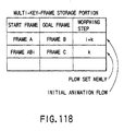
- the animation producing apparatus is characterised in that there is further provided image-frame storage means in which a plurality of image frames are stored and in that said generating means comprises first generating means for generating a first animation from a first image frame to a second image frame by generating a plurality of interpolating frames for interpolating portions between an instructed first image frame and a second image frame of the image frames stored in said image-frame storage means; and second generating means arranged in such a manner that when at least one interpolating frame of a plurality of interpolating frames in the first animation and a third image frame stored in said image-frame storage means are instructed and branching from the first animation is instructed, said second generating means generates a plurality of interpolating frames for interpolating a portion between the instructed interpolating frame in the first animation and the third image frame so as to generate a second animation branched from the instructed interpolating frame.
- the animation producing apparatus is characterized in that there is further provided image-frame storage means for storing a plurality of image frames; and in that said generating means comprises: first generating means for generating a first animation from a first image frame to a second image frame by generating a plurality of interpolating frames for interpolating a portion between the first image frame of the image frames stored in the image-frame storage means and the second image frame; second generating means arranged in such a manner that when at least one interpolating frame of a plurality of interpolating frames in the first animation and a third image frame stored in said image-frame storage means are instructed and branching from the first animation is instructed, said second generating means generates a plurality of interpolating frames for interpolating a portion between the instructed interpolating frame in the first animation and the third image frame so as to generate a second animation branched from the instructed interpolating frame; and third generating means arranged in such a manner that when branching from the first animation is instructed, said third generating means select
- the animation producing apparatus is characterized in that there are further provided image-frame storage means in which the plural image frames are stored; and interpolating frame number calculating means for calculating the number of interpolating frames for interpolating a portion between the instructed interpolating frame in the first animation and the third image frame and the number of interpolating frames for interpolating a portion between the third image frame and the selected interpolating frame in the first animation; and in that said generating means comprises first generating means for producing a first animation from a first image frame to a second image frame by generating a plurality of interpolating frames for interpolating a portion between the instructed first image frame of the image frame stored in the image frame storage means and the second image frame; second generating means arranged in such a manner that when at least one interpolating frame of the plural interpolating frames in the first animation and a third image frame stored in said image-frame storage means are instructed and branching from the first animation is instructed, said second generating means generates a plurality of interpolating frames for interpolating
- the animation producing apparatus is characterized in that there are further provided image-frame storage means in which a plurality of image frames are stored; first generating means for generating a first animation from a first image frame to a second image frame by generating a plurality of interpolating frames for interpolating a portion between the instructed first image frame of the image frames stored in said image-frame storage means and the second image frame; and animation insertion means arranged in such a manner that when at least one interpolating frame of the plural interpolating frames in the first animation and one or a plurality of the third image frame stored in said image-frame storage means are instructed and insertion of one or a plurality of second animations which are different from the first animation into the first animation is instructed, said animation insertion means inserts the second animation from the instructed interpolating frame formed by generating the plurality of the interpolating frames for interpolating a portion between the instructed interpolating frame in the first animation and the third image frame to the third image frame into the first animation following the instructed interpolating frame.
- a recording medium comprising a computer usable medium having computer readable code means embodied therein for causing an animation to be produced comprising key-frame images constituted by one or a plurality of strokes and an interpolating frame image constituted by interpolating strokes produced by interpolating strokes of each key-frame image
- the computer readable program code means in said article of manufacture comprising: computer readable program code means for causing a computer to input the one or a plurality of strokes with respect to the key-frames; computer readable program code means for causing a computer to quantize one or a plurality of strokes input by a user with respect to the key-frames into unit vectors each having a predetermined length; and computer readable program code means for causing a computer to produce interpolated vectors interpolating the corresponding unit vectors based on a changed amount between the corresponding unit vectors between the key-frames.
- the computer usable medium is characterised in that there is further provided a program stored therein, said program being arranged to generate a sequential animation composed of a plurality of image frames and a plurality of interpolating frames by generating the plural interpolating frames for interpolating a portion between the plurality of the supplied image frames, said program being arranged to perform the steps of generating a first animation from a first image frame to a second image frame by generating a plurality of interpolating frames for interpolating a portion between the instructed first image frame of the plurality of the supplied image frames and the second image frame, and generating a second animation branched from the instructed interpolating frame by generating a plurality of interpolating frames for interpolating a portion between the instructed interpolating frame in the first animation and the third image frame when at least one interpolating frame of the plural interpolating frames in the first animation and the third image frame of the plural image frames are instructed and branching from the first animation is instructed.
- the computer medium is characterised in that there is further provided a program stored therein, said program being arranged to generate a sequential animation composed of a plurality of image frames and a plurality of interpolating frames by generating the plural interpolating frames for interpolating a portion between the plurality of the supplied image frames, said program being arranged to perform the steps of generating a first animation from a first image frame to a second image frame by generating a plurality of interpolating frames for interpolating a portion between the instructed first image frame of the plurality of the supplied image frames and the second image frame, generating a second animation branched from the instructed interpolating frame by generating a plurality of interpolating frames for interpolating a portion between the instructed interpolation frame in the first animation and the third image frame when at least one interpolating frame of the plural interpolating frames in the first animation and the third image frame of the plural image frames are instructed and branching from the first animation is instructed, and generating a third animation which is joined from the second animation to
- the present invention provides an animation producing method for producing animation constituted by a key-frame image composed of one or more strokes and an interpolating frame image composed of interpolating strokes which are generated by interpolating a portion between the strokes of each key-frame image, said animation producing method comprising the step of generating interpolating strokes for interpolating portions between one or more strokes input from a user to the key-frame.
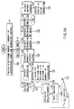
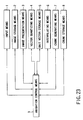
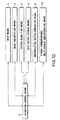
- FIG. 4 is a diagram schematically showing an example of the structure of an animation producing apparatus according to a first embodiment of the present invention.
- the animation producing apparatus comprises an input means 1 for inputting line drawings or the like, the line drawings inputted through the input means 1, an image presentation means 3 for displaying animation or the like generated on the basis of the supplied line drawings, a vector quantizing means 4 for decomposing strokes in the line drawing into a plurality of unit vectors each having a predetermined length, a unit-vector storage means 5 for storing the generated unit vectors, an interpolating means 6 for generating interpolating vector between the two strokes and an animation control means 9 for producing sequential animation by performing control to synchronize the above-mentioned means.
- the structure is constituted as described above.
- the vector quantizing means 4 quantizes each of corresponding strokes between the plurality of the supplied line drawings into unit vectors each having the predetermined length.
- the interpolating means 6 generates interpolating frames between the plural line drawings on the basis of change in the amount between corresponding unit vectors between the plural line drawings and the number of interpolating frames. Thus, animation is generated.
- a term "key-frame” means a line drawing (composed of a (curved or) line segment of change in the movement input by, for example, a user by using the input means 1.
- a term "skeleton" has a concept which is substantially the same as that of the stroke constituting the line drawing.
- interpolating frame means a frame image interpolated between key-frames, the number of the frame images being previously instructed by the user as the number of interpolations.
- production interval means an interval of reproducing time between the interpolating frames.
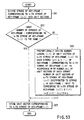
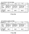
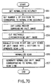
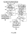
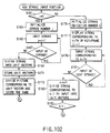
- FIGS. 5A and 5B are flow charts showing the overall processing manipulation of the animation producing apparatus shown in FIG. 4.
- step S1 a state in which input is waited for is realized (step S2).
- step S2 a state in which input is waited for is realized (step S2).
- step S5 a state in which input is waited for is realized (step S2).
- step S5 a state in which input is waited for is realized (step S2).
- step S5 a state in which input is waited for is realized (step S2).
- step S5 a user is able to perform instruction of input of a skeleton (which is sometimes called a "stroke")(step S5) , instruction to reproduce animation (step S21), instruction of the number f of interpolating frames (step S23), instruction of reproducing interval t (step S24), for example, instruction of recording of a movie which is able to serve as an original image (step S25), instruction of completion (step 526) and another instruction (step S27).
- step S25 instruction of completion
- step S27 another instruction
- skeleton number j is initialized (step S7).
- the skeleton number is used to identify a plurality of skeletons which are input by the user.
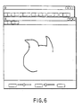
- the user sequentially inputs required skeletons through a user interface of the input means 1 having a structure, for example, as shown in FIG. 6. At this time, each skeleton is given the skeleton number (step S8).
- the vector quantizing means 4 decomposes (quantizes) each of the supplied skeletons into a unit vector (step S10).
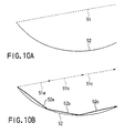
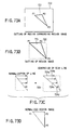
- a skeleton which is a straight line in this case
- FIG. 7B An example case in which a skeleton (which is a straight line in this case) drawn by the user as shown in FIG. 7A is quantized into the unit vector is shown in FIG. 7B.
- the unit vector is a vector having a predetermined length (for example, "1").
- the unit vector is stored in the unit-vector storage means 5 (step S11).
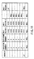
- FIG. 8 shows an example of stored unit vectors in the unit-vector storage means 5.
- the unit-vector storage means 5 stores the values of a plurality of unit vectors obtained by quantizing the plural skeletons (for example, skeletons having numbers 1 to 6) drawn on the key-frame number "0". Note that a fact that no successive vector exists is indicated as "NULL" in FIG. 8.
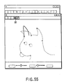
- a key-frame which is one key-frame before (for example, the key-frame having key-frame number "0") is displayed on a predetermined display unit. At this time, it is preferable that the color of the skeleton drawn on key-frame before is changed in accordance with the skeleton number or the skeleton is caused to blink as shown in FIG. 9 in order to facilitate the user to easily drawn a next skeleton.
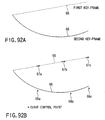
- FIG. 9 shows a case in which the head of a dog is drawn in a key-frame having the key-frame number "0".
- the value of k is updated (step S16).
- the vector quantizing means 4 divides the supplied skeleton (a k - 1 th skeleton) into unit vectors which are then stored in the unit-vector storage means 5 (step S17).
- the skeleton 51 is quantized into unit vectors 51a, 51b and 51c, while the skeleton 52 is quantized into unit vectors 52a, 52b and 52c.
- the interpolating means 6 In accordance with the number f of interpolations communicated in step S23 shown in FIG. 5A, the interpolating means 6 generates an interpolating vector between key-frames having the key-frame numbers "0" and "1", the generated interpolating vector being then stored (step S18).
- the interpolating means 6 obtains interpolating vectors 63a to 63d between the two key-frames.
- FIGS. 14 to 17 A specific example of animation realized by generating the above-mentioned interpolating vector is shown in FIGS. 14 to 17.
- skeleton G1 in the key-frame having the key-frame number "1", as shown in FIG. 15.
- skeleton G0 which is one key-frame before is displayed in such a manner that, for example, color of the key-frame is changed so as to be identified.
- skeleton G2 is drawn in the key-frame having the key-frame number "2", as shown in FIG. 16.
- skeleton G1 which is one key-frame before is displayed in such a manner that, for example, color of the key-frame is changed so as to be identified.
- skeleton G3 is drawn in the key-frame having the key-frame number "3", as shown in FIG. 17.
- skeleton G2 which is one key-frame before is displayed in such a manner that, for example, color of the key-frame is changed so as to be identified.
- the skeletons G0 to G3 drawn on the key-frames as shown in FIGS. 14 to 17 are quantized into unit vectors as described above.
- interpolating vectors are generated in accordance with the number f of interpolations previously instructed by the user so that interpolating frames are generated. As a result, sequential animation is generated.
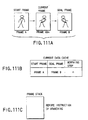
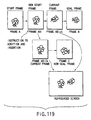
- a user interface as shown in FIG. 18 is displayed on the display unit.
- a window 101 for displaying a plurality of animation items generated by means of the above-mentioned interpolating vectors are displayed so as to be selected by a user is displayed in the lefthand portion of the user interface.
- a first key-frame of animation of the cat is displayed on the window 103, as shown in FIG. 19.
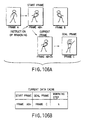
- the recognizing portion 102 recognizes the gesture.
- reproduction of animation corresponding to the gesture is started. That is, animation that cat fawns on the user while mewing is reproduced.
- the movement of the cat and the sound speed are processed in such a manner that the reproducing time interval t is appropriately selected to correspond to the moving speed of the hand so that key-frames and interpolating frames are displayed.
- the recognizing portion 102 recognizes the foregoing gesture so that reproduction of animation corresponding to the gesture is started.
- FIGS. 21 and 22 show another example of animation created by generating interpolating vectors.
- the first embodiment is arranged in such a manner that when a plurality of line drawings indicating the changed shapes of the strokes have been input by a user, each of corresponding strokes between the plurality of the input line drawings is quantized into unit vectors each having a predetermined length. Moreover, interpolating vectors are obtained in accordance with the amount of change between the unit vectors between the plurality of the line drawings and the number of interpolating frames which have previously been instructed. Thus, interpolating frames between the plurality of the line drawings are generated. Thus, animation which moves sequentially as required by the user can easily be generated with a simple structure.
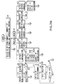
- FIG. 23 is a diagram schematically showing an example of the structure of an animation producing apparatus according to a second embodiment of the present invention.
- the animation producing apparatus comprises an image storage means 2 for storing image data serving as an original image (in a case where the original image is in the form of a sprite structure, a plurality of sprite image data is stored as a set); an image presentation means 3 for displaying, on a predetermined display unit, image data stored in the image storage means 2 and animation or the like generated in accordance with image data; an input means 1 for inputting a stroke to a portion of the image displayed by the image presentation means 3 and required to have movement; a vector quantizing means 4 for decomposing the stroke input through the input means 1 into unit vectors each having a predetermined length; a unit-vector storage means 5 for storing the generated unit vectors; an interpolating means 6 for generating an interpolating vector between the two strokes in accordance with the unit vectors of the two corresponding strokes and correcting (for example,
- a skeletal stroke which is input into the original image by a user as a portion required to have movement and its changed shape are sometimes called a "skeleton".
- the animation producing apparatus has the above-mentioned structure.
- the vector quantizing means 4 quantizes the skeltal skeleton and the skeleton indicating its changed shape into unit vectors each having a predetermined length.
- the interpolating means 6 calculates interpolating vectors in accordance with the amount of change between corresponding unit vectors of the two skeletons and the number of interpolating frames which have been instructed.
- the chunk generating means 7 extracts an image region (a chunk) along each unit vector of the skeltal skeleton and having a predetermined size from the original image.
- the animation control means 9 moves each chunk in accordance with the corresponding unit vector and the interpolating vector to add each chunk to the original image. As a result, a plurality of image frames are generated so that animation is generated.
- key-frame means an original image or an original image to which change in the movement has been input by a user through the input means 1.
- skeleton has substantially the same concept as that of the stroke and means a skeltal portion of an image portion input by the user to a portion of the original image required to have change in the movement and a changed shape of the skeltal skeleton.
- interpolating frame means an interpolating frame image between the key-frames, the number of the interpolating frames being previously instructed by the user as the number of interpolations.
- producing interval is the interval between the interpolating frames in terms of time.
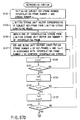
- FIGS. 24A and 24B are flow charts of the overall manipulation of the animation producing apparatus shown in FIG. 23. The same elements as those shown in FIGS. 5A and 5B are given the same reference numerals.
- the structure according to this embodiment is different from that shown in FIGS. 5A and 5B is that the use is permitted to instruct reading of an image serving as an original image in a state in which input is waited for in step S2 (step S3).
- required image data previously input from a scanner or an external unit and stored in the image storage means 2 is read so as to be displayed on a predetermined display unit through the image presentation means 3 (step S4). If the user instructs to input a skeleton (step S5), the user inputs skeltal skeleton for the portion of the image required to have movement by using the displayed image as the key-frame (steps S8 and S9).
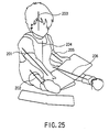
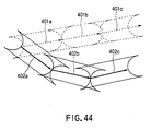
- the skeltal skeleton are skeletons 201 to 206 as shown in FIG. 25.
- the skeltal skeleton are quantized into unit vectors so as to be stored in the unit-vector storage means 5.
- the chunk generating means 7 extracts, from the key-frame, an image region (a chunk) along each Unit vector original the skeltal skeleton and having a predetermined size.
- the image region (the chunk) is stored in the chunk storage means 8 (steps S10 to S12).
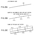
- a skeltal skeleton 201 drawn in the image region of the right arm of a children in the original image shown in FIG. 25 is taken as an example to specifically described the quantization of the skeleton and extraction of the chunk.
- FIG. 26A shows the skeleton 201.
- FIG. 26B shows case in which the skeleton 201 has been quantized into unit vectors 211a to 211c each having a length of "1" similarly to the first embodiment.
- FIG. 26C shows an example of an image region (a chunk) along each of unit vectors 211a to 211c of the skeltal skeleton and having a predetermined size.
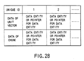
- the vector quantizing means 4 quantizes the skeleton so that a unit vector column is generated. Data of the unit vector is as it is stored or a pointer for a storage region for data of each unit vector is stored.
- the chunk generating means 7 cuts, from the original image, an image region adjacent to each unit vector of the skeltal skeleton, and then performs rotation (affine transformation) and normalization so as to generate the chunks.
- Each of the thus-generated chunk is given a unique ID.
- Image data of the chunk is as it is stored in the chunk storage means 8 or a pointer for the storage region for image data of the chunk is stored in the same in such a manner that the correspondence to the unique ID is made.
- the unique ID given to each chunk is stored in the unit-vector storage means 5 in such a manner that correspondence to data of the unit vector corresponding to the chunk is made.
- unit-vector storage means 5 and the chunk storage means 8 may be eliminated.
- a structure may be employed in which data of the unit vector and data of the chunk are stored in such a manner that they are made to correspond to one unique ID.
- Each unit vector is, as shown in FIG. 29, stored in such a manner that correspondence to sequential skeleton numbers written by the user and the key-frame number of the original image is made.
- step S6 After the skeltal skeletons have been input to the original image, the manipulation proceeds from step S6 to step S13 so that skeletons indicating the changed shape of the skeltal skeleton is input. Also the key-frame number of the image to which the skeleton has been input is as well as updated (in this case the key-frame number is "1").
- the displayed first skeleton 201 is allowed to blink or the color of the same is changed to cause input of the skeleton of the changed shape corresponding to the skeleton 201 (the right arm portion of the children) first input (that is, in the sequential order of the skeleton numbers) in the key-frame having the key-frame number "0".
- skeleton number is given to the newly input skeleton, and then the skeleton is quantized into unit vectors (steps S14 to S17).
- the quantization of the skeleton and storage of the unit vectors are performed similarly to those according to the first embodiment and shown in FIGS. 10A, 10B and 11.
- an interpolating frame for interpolating the portion between the two input key-frames of the skeleton is generated from the two key-frames (steps S18 and S19).
- the interpolating means 6 obtains interpolating vectors 251a to 251d between the unit vectors.
- the process for obtaining the interpolating vectors is similar to that described with reference to FIGS. 13A and 13B.
- the chunk generating means 7 rotates (affine-transforms) the chunks corresponding to the unit vectors of the skeltal skeleton of the original image stored in the chunk storage means 8 in accordance with the interpolating vectors 251a to 251d corresponding to the unit vectors of the skeltal skeletons. Then, the chunk generating means 7 adds the moved chunks to the original image so that an interpolating frame between the first key-frame and the second key-frame is generated.
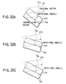
- FIGS. 32A to 32C movement of the chunks corresponding to the unit vectors will now be described. Elements shown in FIG. 32A to 32C which are the same as those shown in FIGS. 13A and 13B are given the same reference numerals.
- FIG. 32A an assumption is made that a unit vector (an original vector) 71a of the skeltal skeleton in the original image and a corresponding interpolating vector 73a are different from each other by an angular degree of ⁇ .
- a chunk 271 corresponding to the original vector 71a is rotated (affine-rotated) and moved by the angular degree of ⁇ so as to be added to the original image.
- a first interpolating frame is generated.
- a chunk 271 corresponding to the original vector 71a is rotated (affine-rotated) and moved by the angular degree of ⁇ so as to be added to the original image.
- a second interpolating frame is generated.
- FIG. 33 shows another example of storage of unit vectors and chunks.
- FIG. 33 shows data of unit vectors and data of chunks are stored in such a manner that they are made to correspond to one another similarly to the structure as shown in FIG. 28. That is, the unit vectors (original vectors) of the skeltal skeleton in the original image data (address information to regions in which image data (a texture) of the chunk is stored) of the chunks corresponding to the original vectors are stored in such a manner that they are made to correspond to the key-frame numbers and skeleton numbers. Moreover, data of each unit vector indicating the changed shape from the skeltal skeleton is stored in such a manner that data is made to correspond to the original vector. In this case, corresponding unit vectors and pointers for the regions in which data of the chunks are stored are stored in each item of each skeleton in one key-frame in such a manner that correspondence is made.
- the user is caused to input the skeletons of the changed shape from the skeltal skeleton input to the original image in the sequential order of the skeleton numbers.
- a process of, for example, the key-frame number "1" is completed (steps S13 to S20).
- step S6 the manipulation proceeds to step S6 so that the key-frame number is updated to input the skeleton of a further changed shape (step S13).
- step S14 the above-mentioned steps S14 to S20 are repeated so that sequential animation composed of the key-frames and interpolating frames is generated.
- a required original image is read from the image storage means 2 in steps S3 and S4 to use the original image as the key-frame similarly to the above-mentioned process (steps S5 to S20).
- the second embodiment has the structure that a skeltal first stroke along an image portion of an original image input by a user and required to have movement and one or more second strokes indicating the changed shape of the first stroke are quantized into unit vectors each having a predetermined length.
- an interpolating vector for interpolating the area between the unit vectors is calculated.
- An image region adjacent to each unit vector of the first stroke extracted from the original image is moved in accordance with the unit vector of the corresponding second stroke and the above-mentioned interpolating vector so as to be added to the original image.
- a plurality of image frames are generated.
- animation which sequentially moves as required by a user can easily be generated with a simple manipulation.
- the process in which the chunk corresponding to the original vector is rotated and moved in accordance with the corresponding interpolating vector sometimes encounters a state shown in FIGS. 34A to 34D. If the amount of change of the skeleton indicating a changed shape of a skeltal skeleton drawn in the original image is large, there arises a problem after each chunk in the original image has moved in that a blank portion is generated in a joint portion between adjacent chunks, for example, as shown in FIG. 34D.
- an animation producing apparatus further comprises a chunk correction means 10 for correcting joint between adjacent chunks after the chunk has been moved.
- FIG. 35 is a diagram showing a schematic structure of the animation producing apparatus according to the third embodiment.
- the same elements as those shown in FIG. 23 are given the same reference numerals. The difference is that the chunk correction means 10 is added.
- the chunk correction means 10 is arranged to calculate deformation of the original chunk in accordance with an interpolating vector when the chunk (the original chunk) of the original vector in the original image is moved.
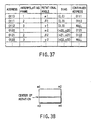
- Data for use to calculate the deformation of the chunk is stored to correspond to the corresponding interpolating vector, for example, as shown in FIG. 36. Note that the address of a region in which data relating the calculation for deformation is stored is stored in the structure shown in FIG. 36.
- data (the rotational angle and bias value) relating to the deformation calculation of the chunk is used between a plurality of interpolating frames, for example, as shown in FIG. 37
- data is continuously stored with "continuation address”.
- the addresses shown in FIG. 37 coincide with the addresses for the deformation calculation.
- Data relating to the deformation calculation of chunks are as well as made to correspond to unit vectors (including interpolating vectors), image data of the chunks, skeleton numbers and key-frame numbers.
- FIG. 39 Another example of the deformation calculation is shown in FIG. 39.
- generation of a gap between adjacent chunks on the same interpolating frame after the chunk has been moved is prevented by extending the chunk corresponding to each interpolating vector in the direction of the vector so that overlapped chunks are generated.
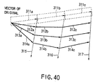
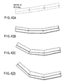
- FIG. 40 Another method is shown in FIG. 40 in which generation of a gap between adjacent chunks on the same interpolating frame after the chunk has been moved is prevented by deforming the chunk corresponding to the interpolating vector into a trapezoid.
- each chunk on the second to third image frames obtained by rotating and moving the original chunk as shown in FIG. 42A is deformed into the trapezoid.
- adjacent chunks on the same frame can satisfactorily be joined to each other, as shown in FIGS. 42B to 42D.
- data for example, coordinates of four points of the chunk realized as a result of the deformation
- data about the deformation calculation of the original chunk is continuously stored with the "continuous addresses" in a case where data above is used between a plurality of interpolating frames.
- the addresses shown in FIG. 43 coincide with the addresses for the deformation calculation shown in FIG. 36.
- Data relating to the deformation calculation of the chunk are made to also correspond to the unit vectors (including interpolating vectors), image data of the chunks, skeleton numbers and key-frame numbers.
- Skeletons and unit vectors obtained by quantizing the skeletons do not correspond to one another depending on the lengths of the skeletons at the original position and the moved position input by the user. If the skeleton at the original position is somewhat shorter than the skeleton at the moved position, the number of unit vectors of the skeleton at the original position is smaller than the number of unit vectors of the skeleton at the moved position. In this case, one unit vector of the skeleton at the moved position corresponds to a plurality of unit vectors on the skeleton at the moved position. Therefore, correspondence between the unit vectors must be considered when the chunk is rotated and moved.
- the vector quantizing means 4 searches the inside portion of the unit-vector storage means 5 and divides a unit vector to correspond to the frame having a larger number of unit vectors for one skeleton, as shown in FIG. 45.
- the number of unit vectors are, in skeleton units, compared between the first frame (the original image) and the second frame. If the number of unit vectors on the second frame for a certain skeleton is four and the number of unit vectors on the first frame is two (unit vectors 501 and 502)(refer to FIG. 46), each of the unit vectors of the first frame is divided into two.
- unit vectors 501a, 501b, 502a and 502b are generated so as to be stored in the unit-vector storage means 5 (see FIG. 46). Moreover, corresponding chunks are divided so that chunks corresponding to the unit vectors 501a, 501b, 502a and 502b are generated. Thus, data of unit vector in four units in the second frame previously stored in the unit-vector storage means 5 and four unit vectors of the first frame obtained by the dividing manipulations are made to correspond to one another (see FIG. 46). The chunks divided between the unit vectors are rotated, moved and superimposed so that interpolating frames are generated.
- FIG. 46 schematically shows an example of storage in the unit-vector storage means 5 in the case where the unit vectors are divided.
- the number of unit vector of the skeleton at the original position is larger than the number of those of the skeleton at the moved position.
- one unit vector of the skeleton at the moved position corresponds to a plurality of unit vectors on the skeleton at the original position. Therefore, correspondence between the unit vectors must be considered when the chunk is rotated and moved.
- the vector quantizing means 4 searches the inside portion of the unit-vector storage means 5 and divides a unit vector to correspond to the frame having a larger number of unit vectors for one skeleton, as shown in FIG. 47.
- the number of unit vectors are, in skeleton units, compared between the first frame (the original image) and the second frame. If the number of unit vectors on the first frame for a certain skeleton is four and the number of unit vectors on the second frame is two (unit vectors 511 and 512)(refer to FIG. 48), each of the unit vectors of the second frame is divided into two.
- unit vectors 511a, 511b, 512a and 512b are generated so as to be stored in the unit-vector storage means 5 (see FIG. 48).
- data of unit vector in four units in the first frame previously stored in the unit-vector storage means 5 and four unit vectors of the second frame obtained by the dividing manipulations are made to correspond to one another (see FIG. 48).
- the chunks on the first frame are rotated, moved and superimposed between the unit vectors so that interpolating frames are generated.
- FIG. 48 schematically shows an example of storage in the unit-vector storage means 5 in the case where the unit vectors are divided.
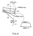
- the chunk generating means 7 cuts, from the original image stored in the image storage means 2, chunks corresponding to the unit vectors. Assuming that the length of the unit vector is l and the angle of the image made from the horizontal direction is ⁇ , an image region 603 having a length L and including a square chunk which has a length of l along the unit vector 601 is cut. At this time, coordinates (X, Y) of a point (an upper left point) serving as a reference for the length L and the image region 603 is expressed by the following Equation (2):
- the image region 603 obtained by the cutting manipulation is rotated by angle ⁇ so that an image region 604 of a larger size is generated.
- a reference point (the upper left vertex) of the chunk 601 which is cut from the image region 604 is expressed by the following Equation (3) when the upper left vertex of the image region 604 is made to be a reference point (0, 0):
- the chunk 602 cut from the image region 604 is superimposed to the moved position.
- the chunk generating means 7 cuts a larger image region including the chunk when the chunk is cut from the original image.
- a normalized chunk having a size (a square each side of which has a length of 1) corresponding to the unit vector is cut from a image region having a larger size, and then the cut chunk is superimposed on the original image.
- blank regions 711 and 712 are generated in the original position for chunks 701 and 702 on a new image frame generated by movements of unit vectors and corresponding chunks 701 and 702.
- the chunk generating means 7 generates interpolating images from background image regions 703 to 706 adjacent to the chunks which are moved (see FIG. 50B).
- background image regions 704 and 705 are blended to cover the blank region 711 as shown in, for example, FIGS. 51A and 51B.
- An obtained blended image can be placed in the blank region 711.
- an image region (a chunk) adjacent to each unit vector of a skeltal skeleton in an original image is deformed (into, for example, a trapezoid) to correspond to the shapes of the skeltal skeleton and the interpolating stroke so as to be superimposed on the original image.
- a blank portion generated in the joint portion between the adjacent chunks when the chunks are moved can be modified.
- corresponding unit vectors and interpolating vectors between the unit vectors of the skeltal skeleton in the original image and skeletons indicating the changed shape are divided to correspond to the shape of the skeleton.
- the chunk of each unit vector of the skeltal skeleton or the chunks divided to correspond to the divided unit vectors are moved so as to be superimposed on the original image.
- the chunk generating means 7 cuts a chunk from an original image in such a manner that an image region including the chunk and having a larger size is cut.
- a normalized chunk having a size (a square having sides each having a length of 1) corresponding to the unit vector is cut, and then superimposed on the original image.
- blended images formed in accordance with the background image adjacent to the chunk is placed in the blank region at the original position for the chunk.
- FIG. 52 is a diagram schematically showing an animation producing apparatus according to a fourth embodiment of the present invention.
- This embodiment has a structure formed in such a manner that a stroke-correspondence administrating means 11 is added to the structure according to the embodiment shown in FIG. 4.
- the stroke-correspondence administrating means 11 determines the correspondence between strokes between two key-frames input through the input means 1 and the correspondence between unit vectors of the corresponding strokes.
- first to third embodiments have the structure that the number of strokes is the same between the key-frames, the number of strokes can be varied between the key-frames.
- a key-frame in this case, a key-frame having a key-frame number, for example, "0”
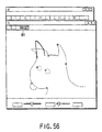
- FIG. 55 shows a case in which the head of a dog is drawn in a key-frame having key-frame number "0".
- a user inputs one stroke on the key-frame having the key-frame number "1" corresponding to the stroke having the stroke number k in order to deform the left ear of having the stroke indication number k in the key-frame having the key-frame number "0".
- the input stroke is given stroke number j (step S15).
- the process of the stroke having a next stroke indication number on the (i - 1)-th key-frame is performed in such a manner that the user clicks a menu button B1 indicating "NEXT" disposed on the display frame shown in FIG.
- step S16 the stroke indication number k is increased by one so that the stroke having a next stroke indication number on the (i - 1)-th key-frame is caused to enhance and display the stroke of the top head portion of the dog, for example, as shown in FIG. 56 (step S17).
- the menu button B1 indicating "NEXT" is required to be selected after all of the plural strokes have been input (step S16).
- step S17 When a next stroke on the (i - 1)-th key-frame is, in step S17, enhanced and displayed, for example, as shown in FIG. 56, the stroke of the i-th key-frame input to correspond to the stroke having the previous stroke number (that is, the (k - 1)-th stroke) is divided into unit vectors by the image presentation means 3 so as to be stored in the unit-vector storage means 5 (step S18).
- the stroke indication number k is a number before it is increased in step S17.
- step S18 shown in FIG. 5B will now be described with reference to a flow chart shown in FIG. 53.
- the stroke in the i-th key-frame input to correspond to the stroke indication number k of the (i - 1)-th key-frame is divided into unit vectors (step S51). If a stroke 52 drawn on the key-frame (a second key-frame) having the key-frame number "1" to correspond to the stroke 51 drawn on the key-frame (a first key-frame) having the key-frame number "0" exists as shown in, for example, FIG. 10A, the stroke 51 has been quantized into unit vectors 51a, 51b and 51c as shown in FIG. 10B (in this case, quantization has been performed in step S39). The stroke 52 is quantized into unit vectors 52a, 52b and 53c in step S49.
- the length of the unit vector may be changed so that the stroke of either of the two key-frames is again quantized to correspond to the larger number of the unit vectors.
- the number of unit vectors are made to be the same between the two strokes. If the number of unit vectors in the stroke 52 is larger than that in the stroke 51 after the stroke 52 has been decomposed into unit vectors each having a predetermined length, the length of the unit vector may be shortened to again quantize the stroke 51 in order to make the number of the unit vectors of the stroke 51 to be the same as the larger number.
- the stroke-correspondence administrating means 11 proceeds the manipulation to step S57 because the number of strokes of the i-th key-frame input to correspond to the stroke indication number k of the (i - 1)-th key-frame is the same (step S53). Thus, the stroke-correspondence administrating means 11 makes correspondent the unit vectors of the two strokes between two key-frames, and then stores the unit vectors in the unit-vector storage means 5.
- the interpolating means 6 In accordance with the number f of interpolations input in step S23 shown in FIG. 5A, the interpolating means 6 generates an interpolating vector between key-frames having the key-frame numbers, for example, "0" and "1", the interpolating vector being stored (step S19).
- the unit-vector storage means 5 has data of unit vectors 61a to 61d obtained by quantizing strokes on the key-frame (the first key-frame) having the key-frame number "0" and data of unit vectors 62a to 62d obtained by quantizing strokes on the key-frame (the second key-frame) corresponding to the strokes on the first key-frame and having the key-frame number "1" in such a manner that data items are given unique identifiers (ID).
- the interpolating means 6 obtains interpolating vectors 63a to 63d between unit vectors of the corresponding stroke between two key-frames. An image frame in which the stroke composed of the interpolating vectors 63a to 63d is drawn is the interpolating frame between the first key-frame and the second key-frame.
- step S18 shown in FIG. 5B will now be described with reference to a flow chart shown in FIG. 53.
- the stroke-correspondence administrating means 11 proceeds the manipulation to step S55.
- the stroke-correspondence administrating means 11 distributes unit vectors of the k-th stroke in the (i - 1)-th key-frame to the k-th key-frame so as to determine the correspondence between the k-th stroke in the (i - 1)-th key-frame and the stroke in the i-th key-frame.
- the number l (1) of unit vectors of the stroke 81 in the first key-frame is "3"
- the number m 21 of the unit vectors in the stroke 82 in the second key-frame is "1”
- the number m 22 of the unit vectors in the stroke 83 in the second key-frame is "2”. Therefore, the number l(1) 1 of the unit vectors of the stroke 81 in the first key-frame allotted to the stroke 82 is "1".
- the number l(1) 2 of the unit vectors of the stroke 81 in the first key-frame allotted to the stroke 83 is "2".
- the strokes of either of the key-frames may again be quantized to correspond to the larger value to make l(1) and m 21 + m 22 to be the same between the two key-frames.
- the stroke 81 may again be quantized in order to make the number of the unit vectors of the stroke 81 to be the same as the larger number.
- step S57 unit vectors of the corresponding strokes between the two key-frames are stored in the unit-vector storage means 5 in such a manner that the correspondence is made.
- the interpolating means 6 In accordance with the number f of interpolations input in step S23 shown in FIG. 5A, the interpolating means 6 generates an interpolating vector between the key-frames having key-frame numbers, for example, "0" and "1" to store the interpolating vector (step S19).
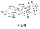
- the method of generating the interpolating vector shown in FIG. 59 is an independent interpolation in which unit vectors of a pair of corresponding unit vectors are independently used to generate interpolating vectors.
- Interpolating points 93e and 93f and 93g and 93h are obtained for the pair of the unit vectors 91b and 92b.
- Interpolating points 93e and 93f and 93i and 93j are obtained for the pair of the unit vectors 91c and 92c.
- the interpolating points are connected to one another so that interpolating vectors 94a to 94c and 95a to 95c are generated. That is, an interpolating vector 94a is generated from the pair of the unit vectors 91a and 92a by connecting the interpolating points 93a and 93c to each other. Moreover, an interpolating vector 95a is generated by connecting the interpolating points 93b and 93d to each other.
- An interpolating vector 94b is generated from the pair of the unit vectors 91b and 92b by connecting the interpolating points 93e and 93g to each other. Moreover, an interpolating vector 95b is generated by connecting the interpolating points 93f and 93h to each other.
- An interpolating vector 94c is generated from the pair of the unit vectors 91c and 92c by connecting the interpolating points 93g and 93i to each other. Moreover, an interpolating vector 95c is generated by connecting the interpolating points 93h and 93j to each other.
- FIGS. 60A and 60B show an example of unit vectors between the corresponding strokes stored in the unit-vector storage means 5.
- FIGS. 60A and 60B show a case in which an individual table is prepared for each key-frame so that the correspondence between corresponding unit vectors are stored and administrated in each table in unit vector units.
- the table of the first key-frame is arranged to store data of the unit vector, or a pointer for a storage region in which the unit vector is stored. Moreover, a unique ID identifiers of a unit vector on a second key-frame corresponding to the unit vector or a pointer for a storage region, in which data of the unit vector is stored, is stored to correspond to the unique ID (identifier) given to the unit vector of one or more strokes drawn on the key-frame.
- the table of the second key-frame is arranged to store data of the unit vector, or a pointer for a storage region in which the unit vector is stored.
- a unique ID identifiers of a unit vector on a third key-frame corresponding to the unit vector or a pointer for a storage region, in which data of the unit vector is stored is stored to correspond to the unique ID (identifier) given to the unit vector of one or more strokes drawn on the second key-frame.
- FIGS. 61A and 61B shows another example of storage of the unit vector between corresponding strokes in the vector quantizing means 4.
- FIGS. 61A and 61B show a case in which an individual table is prepared for each key-frame to store and administrate the correspondence between unit vectors on the corresponding key-frames in each table and in unit vector group.
- grouping is performed for each of corresponding strokes of each key-frame. Since a unit vector 91a on the first key-frame and the unit vector 92a of the first stroke on the second key-frame correspond to each other in an example case shown in FIG. 59, they belong to the same group. Since unit vectors 91b and 91c on the first key-frame and unit vectors 92b and 92c of the second stroke on the second key-frame correspond to one another, they belong to the same group.
- the table of the first key-frame is arranged to store data of the unit vector or a pointer for a storage region, in which the unit vector is stored. Moreover, information (an identifier for the group or a pointer for a storage region in which data of the corresponding unit vector belonging to the group) for linking to the group to which the unit vector belongs is stored to correspond to unique ID (identifier) given to each unit vector of one or more strokes drawn on the key-frame. As shown in FIG.
- the table of the second key-frame is arranged to store data of the unit vector or a pointer for a storage region in which the unit vector is stored and information (an identifier for the group or a pointer for a storage region in which data of the corresponding unit vector belonging to the group) for linking to the group to which the unit vector belongs) to correspond to the unique ID (identifier) given to each unit vector of one or more strokes drawn on the key-frame.
- unit vectors of the first key-frame given unit ID "1 - 1" and "1 - 2" and unit vectors of the second key-frame given unique ID "2 - 1", "2 - 2" and "2 - 3" belong to "Group 1". Therefore, unit vectors of the second key-frame given unique ID "2 - 1", “2 - 2" and "2 - 3" correspond to the unit vectors of the first key-frame given unique ID "1 - 1" and "1 - 2".
- a flow chart shown in FIG. 54 shows a detailed process in step S19 shown in FIG. 5B.
- Either of the first interpolating method or the second interpolating method can be selected in accordance with an instruction from a user or a previous determination.
- the independent interpolation which is the first interpolating method
- the manipulation proceeds to step S69 so that the independent interpolation is performed as described with reference to FIG. 59.
- the second interpolating method has been instructed or set (step S61)
- the manipulation proceeds to step S63 so that number F of the interpolating frame of the number f of interpolations with which the independent interpolation is started is determined.
- step S65 the manipulation proceeds to step S65 so that the combination of unit vectors having the corresponding relationship of the first to (F - 1)-th interpolating frames is changed to correspond to the number of unit vectors included in the strokes.
- the interpolating vectors are generated.
- the principle of the generation will briefly be described.
- the number l(i - 1) j ' of the k-th stroke in the (i - 1)-th key-frame which is distributed to the j-th stroke in the i-th key-frame input to correspond to the k-th stroke in the (i - 1)-th key-frame can be expressed by Equation (5):
- unit vectors of the k-th stroke in the (i - 1)-th key-frame are distributed by the number l(i - 1) j ' in place of the number l(i - 1) j to the j-th stroke of the i-th key-frame.
- the correspondence between the unit vectors included in the j-th stroke in the i-th key-frame and the unit vectors distributed to the j-th stroke is used to generate the interpolating vectors.
- the number of unit vectors of the first key-frame allotted to the second stroke of the second key-frame is "3" because of Equation (5) which are unit vectors 91a, 91b and 91c. Therefore, in the corresponding relationship between the unit vectors, start points and end points of the corresponding unit vectors are connected to one another similar to the method shown in FIG. 59. The connected region is equally divided by the number corresponding to the number of frames to be interpolated, that is, by three in this case.
- interpolating vectors 97a, 97b, 98a and 98b are generated.
- interpolating vectors 99a to 99c and 100a to 100c are generated.
- step 567 interpolating vectors for the F-th to f-th interpolating frames are generated by the independent interpolation shown in FIG. 59.
- unit vectors of the k-th stroke in the (i - 1)-th key-frame are distributed by the number l(i - 1) j to the j-th stroke of the i-th key-frame so that interpolating vectors are generated in accordance with the correspondence between the unit vectors included in the j-th stroke in the i-th key-frame and the unit vectors distributed to the j-th stroke.
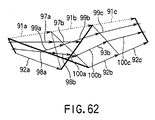
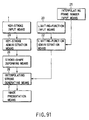
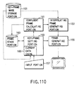
- FIG. 63 is a diagram schematically showing an example of the structure of an animation producing apparatus according to a fifth embodiment of the present invention. Elements which are shown in FIG. 63 and which are the same as those shown in FIG. 52 are given the same reference numerals. As shown in FIG. 63
- the animation producing apparatus comprises an image storage means 8 for storing image data serving as an original image (in a case where the original image is in the form of a sprite structure, a plurality of sprite image data is stored as a set); an image presentation means 3 for displaying, on a predetermined display unit, image data stored in the image storage means 8 and animation or the like generated in accordance with image data; an input means 1 for inputting a stroke to a portion of the image displayed by the image presentation means 3 and required to have movement; a vector quantizing means 4 for decomposing the stroke input through the input means 1 into unit vectors each having a predetermined length; a unit-vector storage means 5 for storing the generated unit vectors; an interpolating vector generating means 6 for generating an interpolating vector between the two strokes in accordance with unit vectors of the corresponding two strokes; a stroke-correspondence administrating means 11 for determining the correspondence between the strokes input through the input means 1 and the correspondence between the unit vectors of the corresponding
- the animation producing apparatus has the above-mentioned structure.
- the stroke-correspondence administrating means 11 determines the correspondence between the strokes.
- the vector quantizing means 4 quantizes the skeltal strokes and strokes indicating the changed shape into unit vectors each having a predetermined length. In accordance with the number of unit vectors of each of the corresponding strokes, the stroke-correspondence administrating means 11 determines the correspondence between the unit vectors between the corresponding strokes.
- the interpolating means 6 generates interpolating vectors in accordance with the amount of change between the corresponding unit vectors of the corresponding stroke s and a predetermined number of interpolating frames.
- the unit-image generating means 13 extracts, from the original image, an image region (a unit image) having a predetermined size along each unit vector of the skeltal stroke.
- the animation control means 9 moves each unit image in accordance with the corresponding unit vector and the interpolating vector so as to be superimposed on the original image so that a plurality of image frames are generated. Thus, animation is generated. Since the manipulation which is performed by the animation producing apparatus shown in FIG. 63 is similar to that described with reference to FIGS. 24A, 24B and 25, the manipulation is omitted from description.
- FIGS. 24A and 24B A flow chart of the overall manipulation of the animation producing apparatus shown in FIG. 63 is shown in FIGS. 24A and 24B.
- step S13 to S21 The user is caused to input the stroke of the changed shape with respect to the skeltal stroke input to the original image. Then, for example, a process for key-frame number "1" is ended (steps S13 to S21).
- step S6 the manipulation proceeds to step S6 so that the key-frame number is updated to input the stroke of the further changed shape (step S13).
- steps S14 to S21 are repeated so that sequential animation composed of the key-frames and their interpolating frames is generated.
- a required original image may be read from the image storage means 8 in steps S3 and S4 to use it as the key-frame similarly to the above-mentioned processes (steps S5, S6 and S13 to S21).
- the interpolating vectors are read from the unit-vector storage means 5 and the corresponding unit images are read from the unit-image storage means 15. Then, they are drawn by the image presentation means 3 so as to be displayed on the predetermined display unit.
- the corresponding strokes and corresponding unit vectors do not always correspond to one another. That is, the numbers of corresponding unit vectors between the corresponding strokes are not the same.
- the number of unit vectors of the stroke at the original position is smaller than the number of strokes at the moved position.
- one unit vector of the stroke at the original position corresponds to a plurality of unit vectors on the stroke at the moved position.
- the vector quantizing means 4 searches the inside portion of the unit-vector storage means 5 and divides a unit vector to correspond to the frame having a larger number of unit vectors for one stroke, as shown in FIG. 64.
- the number of unit vectors are, in stroke units, compared between the first frame (the original image) and the second frame. If the number of unit vectors on the second frame for a certain stroke is four and the number of unit vectors on the first frame is two (unit vectors 501 and 502)(refer to FIG. 65), each of the unit vectors of the first frame is divided into two.
- unit vectors 501a, 501b, 502a and 502b are generated so as to be stored in the unit-vector storage means 5 (see FIG. 65).
- FIG. 65 schematically shows an example of storage in the unit-vector storage means 5 in the case where the unit vectors are divided.
- the number of unit vector of the stroke at the original position is larger than the number of those of the stroke at the moved position.
- one unit vector of the stroke at the moved position corresponds to a plurality of unit vectors on the stroke at the original position. Therefore, correspondence between the unit vectors must be considered when the unit image is rotated and moved.
- the vector quantizing means 4 searches the inside portion of the unit-vector storage means 5 and divides a unit vector to correspond to the frame having a larger number of unit vectors for one stroke, as shown in FIG. 66.
- the number of unit vectors are, in stroke units, compared between the first frame (the original image) and the second frame. If the number of unit vectors on the first frame for a certain stroke is four and the number of unit vectors on the second frame is two (unit vectors 511 and 512)(refer to FIG. 67), each of the unit vectors of the second frame is divided into two.
- unit vectors 511a, 511b, 512a and 512b are generated so as to be stored in the unit-vector storage means 5 (see FIG. 67).
- FIG. 67 schematically shows an example of storage in the unit-vector storage means 5 in the case where the unit vectors are divided.
- the unit-image generating means 13 cuts, from the original image stored in the image storage means 8, a unit image corresponding to the unit vector. Assuming that the length of the unit vector is l and the angle of the image made from the horizontal direction is ⁇ , an image region 603 having a length L and including a square unit image which has a length of l along the unit vector 601 is cut. At this time, coordinates (X, Y) of a point (an upper left point) serving as a reference for the length L and the image region 603 is expressed by the above-mentioned Equation (2).
- the cut image region 603 is rotated by an angular degree of ⁇ so that an image region 604 having a larger size is generated.
- the unit image 602 cut from the image region 604 is superimposed on the image at the moved position.
- the unit-image generating means 13 cuts a unit image from an original image in such a manner that a larger image region including the unit image is cut. Moreover, a unit image corresponding to the unit vector and having a normalized size (a square having sides 1) is cut from the above-mentioned larger image region so as to be stored in the unit-image storage means 15.
- FIG. 69 is a diagram showing an example of the structure of an animation producing apparatus according to a sixth embodiment of the present invention.
- the animation producing apparatus comprises an image storage means 8 for storing image data serving as an original image (in a case where the original image is in the form of a sprite structure, a plurality of sprite image data is stored as a set); an image presentation means 3 for displaying, on a predetermined display unit, image data stored in the image storage means 8 and animation or the like generated in accordance with image data; an input means 1 for inputting a stroke to a portion of the image displayed by the image presentation means 3 and required to have movement; a vector quantizing means 4 for decomposing the stroke input through the input means 1 into unit vectors each having a predetermined length; a unit-vector storage means 5 for storing the generated unit vectors; an interpolating vector generating means 6 for generating an interpolating vector between the two strokes in accordance with unit vectors of the corresponding two strokes; a stroke
- the unit image in the form of a quadrangle except for a square and a rectangle is cut because of the relationship with the adjacent unit image in a case where the image region is, for example, a bent elbow as shown in FIG. 68.
- Irregular shape unit images except for the predetermined shape, such as the square and rectangle require a complicated process when the unit image is stored in the unit-image storage means 15 comprising a memory such as a RAM.
- the unit-image normalizing means 12 shapes a unit image which is not a square or a rectangle into a regular shape such as a square or a rectangle when the unit image is stored in the unit-image storage means 15 (normalization of a unit image). Then, the normalized unit image is stored in the unit-image storage means 15.
- the image presentation means 3 reads interpolating vectors from the unit-vector storage means 5 and reads unit images corresponding to the interpolating vectors from the unit-image storage means 15. If the read unit images are normalized unit images, the image presentation means 3 restores the shape to the original shape, and then performs drawing and displays the drawn image on the predetermined display unit.
- the "normalization” is an manipulation for vertically and horizontally expanding a unit image into a square or a rectangle.
- a normalized unit image exhibiting excellent preserbility (excellent accuracy in the normalization) of image data can be obtained in proportion to the fineness of extending lines of the original unit image.
- an accuracy is set with which a quadrangular unit image except for a square or a rectangle is normalized is set.
- the accuracy may be instructed by, for example, a user (step S51).
- the number L of extension lines corresponding to the accuracy in the instructed normalization is set (step S52).
- the unit-image generating means 13 cut, from an original image stored in the image storage means 8, a region 702 surrounding a unit image (a quadrangle surround by points P1, P2, P3 and P4) 701 corresponding to unit vectors (step S53).
- a rectangular region 703 circumscribing the unit image is cut (step S54).
- the right and left sides of the unit image 701 are equally divided into L sections, and corresponding divided points on the right and left sides are connected to one another so that scan lines 704a to 704e are generated.
- the upper and lower sides of the unit image 701 are equally divided with a predetermined number of divisions, for example, "2", corresponding to a normalization accuracy which has been instructed. Then, the divided points of the upper and lower sides are connected to one another so that a scan line 704f is generated (step S55). As shown in FIG. 71C, the generated scan lines 704a to 704f are rotated and/or moved to suit the circumscribing rectangle 703 so that the scan lines are normalized (step S56). As shown in FIG. 71D, image data adjacent to the scan lines are rotated and/or moved to correspond to the normalized scan lines so that a normalized unit image is generated (step S57). The process may be performed by, for example, a method called "Bilinear Warping". The method has been disclosed in Modern Image Processing: Warping, Morphing, and Classical Techniques (Academic Press, pp. 102 to 108).
- the method of normalizing a unit image shown in FIGS. 71A to 71D is arranged to normalize a quadrangular unit image.
- a method of normalizing a triangular unit image that is, a method of normalizing a triangular unit image into a regular triangle, such as a right angled triangle, right angled and isosceles triangle, will now be described with reference to FIGS. 73A to 73D.
- the unit-image generating means 13 cuts, from an original image stored in the image storage means 8, a region 722 surrounding a unit image (a triangle surround by points P1, P2 and P3) 721 corresponding to a unit vector (step S53). Then, a rectangular region 723 circumscribing the unit image 721 is cut from the above-mentioned cut region, as shown in FIG. 73B (step S54). As shown in FIG. 73C, the right and left sides of the unit image 721 are equally divided into L sections. Then, the corresponding divided points on the right and left sides are connected to one another so that scan lines 724a to 724d are generated (step S55). Then, as shown in FIG.
- the generated scan lines 724a to 724d are moved to fit a right angle of the circumscribing rectangle 723 so that the scan lines are normalized (step S56).
- image data adjacent to the scan lines is rotated and/or moved to correspond to the normalized scan lines so that a normalized unit image is generated (step S57).
- the process may be performed by, for example, a method called "Bilinear Warping". The method has been disclosed in Modern Image Processing: Warping, Morphing, and Classical Techniques (Academic Press, pp. 102 to 108). The process for normalizing the scan lines is performed similarly to the method shown in FIGS. 72A to 72C.
- FIGS. 74 to 78 show a modification of the sixth embodiment.
- the sixth embodiment is arranged in such a manner that a unit image is restored to the original image and then superimposed. If the stroke is deformed, the vertexes are not always disposed clockwise. This modification enables deformation, drawing and superimposition to be performed if the vertexes are not disposed clockwise.
- FIG. 74 is a diagram schematically showing an example of the structure of an animation producing apparatus according to the modification of the sixth embodiment.
- the animation producing apparatus comprises an image storage means 8 for storing image data serving as an original image (in a case where the original image is in the form of a sprite structure, a plurality of sprite image data is stored as a set); an image presentation means 3 for displaying, on a predetermined display unit, image data stored in the image storage means 8 and animation or the like generated in accordance with image data; an input means 1 for inputting a stroke to a portion of the image displayed by the image presentation means 3 and required to have movement; a vector quantizing means 4 for decomposing the stroke input through the input means 1 into unit vectors each having a predetermined length; a unit-vector storage means 5 for storing the generated unit vectors; an interpolating vector generating means 6 for generating an interpolating vector between the two strokes in accordance with unit vectors of the corresponding two strokes
- FIGS. 75A, 75B and 78 show a method which enables a chunk to be deformed and drawn even if the vertexes are not disposed clockwise.
- FIGS. 75A and 75B show four drawing cases.
- the correspondence between a case (T1) in which vertexes are disposed clockwise and a case (T1 reverse) which is a reverse case of T1 is shown.
- the correspondence between a case (T1 Cross 1) in which the upper and lower sides have a twisted relationship and a case (T1 Cross 1 Reverse) is shown. Selection of correspondence is shown in such a manner that four scan lines are taken as an example.
- FIG. 76 shows the correspondence between a case (T1 Cross 2) in which the right and left sides have a twisted relationship and a case (T1 Cross 2 Reverse) which is a reversed case of the case (T1 Cross 2).
- deformation is performed in accordance with scan lines in the vertical direction in place of the horizontal scan lines.
- FIG. 77 shows correspondence of scan lines to a case (convex 1) in which the overall shape is twisted relative to side 1-3, a case (convex 2) in which the overall shape is twisted relative to side 2-4 and a case (convex) in which the overall shape is twisted relative to side 1-2.
- FIG. 78 shows correspondence of scan lines to a case (convex 4) in which the overall shape is twisted relative to side 1-4, a case (convex 5) in which the overall shape is twisted relative to side 3-2 and a case (convex 6) in which the overall shape is twisted relative to side 3-4.
- Chunk must be drawn in all topological form of specified chunk vertex with a scan rule which maintains only a scan-line image information between regular chunk image and destination chunk image. Examples of scan rule of creating chunks and drawing chunks are shown in FIGS. 81A to 84. It is important to enable mapping on any chunk vertex topological pattern anyway.
- FIG. 79 is a diagram schematically showing an example of the structure of an animation producing apparatus according to a seventh embodiment of the present invention.
- the animation producing apparatus comprises an image storage means 8 for storing image data serving as an original image (in a case where the original image is in the form of a sprite structure, a plurality of sprite image data is stored as a set); an image presentation means 2 for displaying, on a predetermined display unit, image data stored in the image storage means 8 and animation or the like generated in accordance with image data; an input means 1 for inputting a stroke to a portion of the image displayed by the image presentation means 2 and required to have movement; a vector quantizing means 4 for decomposing the stroke input through the input means 1 into unit vectors each having a predetermined length; a unit-vector storage means 5 for storing the generated unit vectors; an interpolating vector generating means 6 for generating an interpolating vector between the two strokes in accordance with unit vectors of the corresponding two
- the special effect generating means 17 performs a predetermined calculation process for realizing a special effect instructed from, for example, a user. Thus, the correspondence of a position into which the special effect is inserted to a unit image in the generated animation is calculated. Data for calculating the special effect is stored in such a manner that data is made to correspond to the calculated unit image so that data is inserted into a position in the animation instructed by a user.
- FIG. 80 schematically shows the correspondence made between the unit image extracted from an original image and data for calculating a special effect.
- a unit image generated by the unit-image generating means 13 is given a unique ID.
- Image data of the unit image or a pointer for a region in which image data of the unit image is stored is stored in the unit-image storage means 15 in such a manner that correspondence to the unique ID is made.
- the unique ID given to each unit image is stored in the unit vector storage means 4 in such a manner that the correspondence to data of the unit vector corresponding to the unit image is made.
- data for calculating the special effect or the pointer for the region in which data for calculating the special effect is given the unique ID of the unit image of the frame corresponding to the position in the generated animation instructed by the user.
- the pointer having the unique ID is stored in, for example, unit-image storage means 15.
- the unit-vector storage means 5 and the unit-image storage means 15 are permitted not to individually be provided and they are formed into the table in the same storage region to store data of the unit vector and data of the unit image in such a manner that they are made to correspond to one unique ID. In this case, a field is required to be provided in the same table to write data for calculating the special effect.
- the image presentation means 2 When presentation of the animation into which the special effect has been inserted is performed, the image presentation means 2 reads the interpolating vector from the unit-vector storage means 5 and reads a unit image corresponding to the interpolating vector and data for calculating the special effect from the unit-image storage means 15. Then, the image presentation means 2 subjects the read unit image to the special effect in accordance with data for calculation, and then draws an image so as to be displayed on the predetermined display unit.
- a portion in one frame is subjected to the special effect (that is, each unit image is subjected to the special effect) or the overall frame is subjected to the special effect.
- a code for example "REPEAT" may be made to correspond to each unit image so as to be stored in place of making data for calculating the special effect to correspond to each of all unit images in the frame before storage.
- the manipulation speed for example, "v1" may be made to correspond to each unit image together with the code "REPEAT" when storage is performed.
- the unit image and data for calculating the special effect are made to correspond to each other so as to be stored and each unit image is subject to a different special effect as shown in FIG. 82, correspondence to data for calculating the special effect which is different for each unit image or a pointer to a storage region for data for the calculations is made when storage is performed.
- FIGS. 81 and 82 show a state in which the unit-vector storage means 5 and the unit-image storage means 15 are not individually provided and they are formed into a table in the same storage region so as to store data of unit vectors, data of unit images and data for calculating the special effect while they are made to correspond to one unique ID.
- the special effect may be inserted in such a manner that a user uses a mouse or the like to instruct a position in the presented animation at which the special effect is inserted.
- a menu window for selecting a special effect from a plurality of effects may be displayed through the image presentation means 2, as shown in FIG. 83.
- FIG. 84 shows an example of animation into which a special effect has been inserted when "COLOR INVERSION" is selected from the menu window, and repetition of "COLOR INVERSION" is instructed.
- the methods of producing animation according to the fourth to seventh embodiments may be formed into a program which can be executed by a computer and stored in a recording medium, such as a floppy disk, a hard disk, a CD-ROM or a semiconductor memory, so as to be distributed.
- a recording medium such as a floppy disk, a hard disk, a CD-ROM or a semiconductor memory
- FIG. 85 shows the structure of a computer system for performing the animation producing method according to the present invention.
- the computer system comprises, for example, a personal computer having a CPU 1001 for performing calculations, an input portion 1002 such as a keyboard, a pointing device or a mouse, an output portion 1003 such as a display and a loudspeaker unit, ROM 1004 and RAM 1005 serving as main storage portions, a hard disk drive 1006 serving as an external storage unit, a floppy disk drive 1007 and an optical disk unit 1008 which are connected to one another by a bus 1009.
- a personal computer having a CPU 1001 for performing calculations, an input portion 1002 such as a keyboard, a pointing device or a mouse, an output portion 1003 such as a display and a loudspeaker unit, ROM 1004 and RAM 1005 serving as main storage portions, a hard disk drive 1006 serving as an external storage unit, a floppy disk drive 1007 and an optical disk unit 1008 which are connected to one another by a bus 10
- a program for executing the animation producing method according to the foregoing embodiments and image data are stored in any one of the recording mediums such as the hard disk drive 1006, the floppy disk drive 1007 and the optical disk unit 1008.
- image data such as the stroke and instruction of a special effect, read from the recording medium is subjected to an animation processing process in the CPU 1001.
- Generated animation is transmitted from the output portion 1003.
- the animation processing manipulation according to the present invention can be performed by using a usual personal computer.
- a ninth embodiment of the present invention will now be described. Although the interpolation is performed linearly in the first to eighth embodiments, this embodiment is arranged in such a manner that information for limiting the changed shape of the stroke is input and a interpolating stroke is generated in accordance with input information.
- the same elements as those shown in FIG. 63 are given the same reference numerals.
- FIG. 86 is a diagram schematically showing an example of the structure of an animation producing apparatus according to a ninth embodiment of the present invention.
- the animation producing apparatus comprises a key-stroke input means 1 for inputting strokes or the like which must be registered to the key-frame; a key-stroke quantizing means 4 for decomposing (quantizing) the stroke into unit vectors each having an arbitrary length; a unit-vector storage means 5 for storing the unit vectors; a limiting-stroke input means 21 for inputting limiting strokes for limiting deformation of interpolating strokes which are generated for interpolating the key strokes input by the key-stroke input means 1 between key-frames; an interpolating frame number input means 25 for inputting the number of interpolating frames for interpolating between key-frames; a limiting-stroke quantizing means 23 for decomposing (quantizing) the limiting stroke into unit vectors, the number of which is the same as the number of the interpolating frames; an interpolating vector generating means 6
- FIGS. 87A to 87D are flow charts showing the overall manipulation of the animation producing apparatus shown in FIG. 86.
- step S3 the user is able to instruct reading of an image (step S3), input of key strokes (step S4), input of limiting strokes (step S5), reproduction of animation (step S6), number f of interpolating frames through the interpolating frame number input means 5 (step S7), completion (step S8) and another process (step S9).
- the stroke number j which is input to the key-frame is initialized (step S93).
- the stroke number is an identifier for identifying a plurality strokes input by the user.
- the user uses a mouse or a tablet through a user interface of the key-stroke input means 1 to draw strokes (curves) serving as skeleton in a portion on a prepared bitmap image in which animation is required so as to sequentially input required strokes.
- strokes curves
- each stroke is given stroke number (steps S95 to S97).
- each of input key strokes is decomposed (quantized) into unit vectors each having a predetermined length by the key-stroke quantizing means 4 (step S99).
- the unit vectors of the key strokes generated by the key-stroke quantizing means 4 are stored in the unit-vector storage means 5 (step S101).
- the stroke number given to each stroke drawn in the first key-frame is made to be stroke indication number k.
- the display color of the k-th key stroke is changed or the k-th key stroke is allowed to blink to cause a user to input the stroke of the second key-frame corresponding to the k-th key stroke of the first key-frame (step S105).
- the user input a key stroke 52 of the second key-frame corresponding to the key stroke 51 of the first key-frame (step S107), as shown in, for example, FIG. 10A.
- a plurality of key stroke of the second key-frame corresponding to the k-th key stroke of the first key-frame may exist.
- the key stroke having the indicating number k + 1 on the first key-frame is enhanced and displayed.
- the user is caused to input the key stroke of the second key-frame corresponding to the k + 1 th key stroke of the first key-frame.
- the key stroke of the second key-frame input to correspond to the key stroke of the previous key stroke (that is, the k-th stroke) is divided into unit vectors by the key-stroke quantizing means 4 (see FIG. 10B) so as to be stored in the unit-vector storage means 5 (step S111).
- step S69 A process which is performed when the user has instructed input of the limiting stroke (step S69) will now be described with reference to a flow chart shown in FIG. 87C.
- the limiting-stroke input means 21 is used to input limiting strokes when the key stroke input by using the key-stroke input means 1 is deformed.
- the strokes are input by drawing strokes on a bitmap image along a route along which the end points of the key strokes are required to drawn.
- limiting stroke number g is given to each limiting stroke (steps S123 to S125).
- g is increased by one so that next key strokes are sequentially enhanced and displayed to cause input of the limiting stroke.
- the limiting-stroke quantizing means 23 quantizes each limiting stroke into unit vectors, the number of which is the same as the number f of the interpolating frames instructed through the interpolating frame number input means 25 and stores the unit vectors of the limiting strokes (steps S127 to S129).
- step S121 If a plurality of key-frames exist, input of the limiting stroke is indicated (step S121).
- the stroke indication number k is initialized (step S131). Then, a key stroke of the present key-frame having the first correspondence relationship with the previous key-frame is displayed on the predetermined display unit. Then, input of the limiting stroke to the displayed key stroke having the above-mentioned correspondence relationship is waited for (step S133).
- step S133 When the user has input the limiting stroke to the key stroke having the first correspondence relationship, k is increased by one.
- key strokes having next correspondence relationship are sequentially enhanced and displayed to cause input of the limiting stroke to the foregoing key stroke (steps S135 to S137).
- the limiting-stroke quantizing means 23 quantizes each limiting stroke into unit vectors, the number of which is the same as the number f of interpolating frames instructed through the interpolating frame number input means 25 so that the unit vectors of the limiting strokes are stored (step S139).
- step S71 A process which is performed when the user has instructed to reproduce the animation (step S71), that is, generation of the interpolating frames will now be described with reference to a flow chart shown in FIG. 87D.
- step S141 Number s of the key-frame for use to generate the interpolating frame, number t of the interpolating frame of the subject which must be generated and number user of the key stroke of the subject which must be processed are initialized (step S141). Similarly to the foregoing example, unit vectors of the key stroke having the correspondence relationship and registered to the first and second key-frames are taken out from the unit-vector storage means 5 in the ascending order of the key stroke number so that interpolating vector strokes are sequentially generated (step S143).
- a process of the interpolating vector generating means 6 for generating interpolating vectors in a case where the limiting stroke is defined to be locus of ends of key strokes which passes during the animation process from the first key-frame to the second key-frame will now be described with reference to FIGS. 88A to 88C and 89.
- FIG. 88A An assumption as shown in FIG. 88A is made that a key stroke (a first key stroke) 31 of the first key-frame and a key stroke (a second key stroke) 32 of the second key-frame corresponding to the first key-frame exist and limiting strokes for use to generate interpolating strokes for the key strokes 31 and 32 are indicated with limiting strokes 33 and 34 which connect the ends points to each other.
- the limiting stroke unit vectors generated by the interpolating vector generating means 6 are sequentially connected from the ends of the first and second key strokes so that the position of the end of the interpolating stroke is defined (step S145).
- the number f of the interpolating frames input through the interpolating frame number input means 25 is "2" as shown in FIG. 88B
- End points of the first interpolating stroke of the two interpolating strokes are points 35a and 36a which interior-divide the limiting strokes 33 and 34 from the end point of the first key stroke 31 at 1:2.
- End points of the second interpolating stroke are points 35b and 36b which interior-divide the limiting strokes 33 and 34 from the end point of the first key stroke 31 at 2:1. Then, the start and end points of the first key stroke 31 are connected to each other so that a base line 37 of the first key stroke is formed. The ends points 35a and 36a of the first interpolating stroke are connected to each other so that a base line of the first interpolating stroke is formed. Moreover, end points 35b and 36b of the second interpolating stroke are connected to each other so that a base line of the second interpolating stroke is formed. The start and end points of the second key stroke 32 are connected to each other so that a base line of the second key stroke is formed.
- unit vectors constituting the key stroke (the first key stroke) of the first key-frame obtained by the key-stroke quantizing means 4 and the key stroke (the second key stroke) of the second key-frame corresponding to the first key-frame are combined.
- the combination of unit vectors are performed at a ratio corresponding to the position of the interpolating frame which is the subject in consideration of the first key stroke, the second key stroke and the length of the base line connecting the ends of the interpolating strokes.
- a interpolating vector is obtained.
- a specific example is shown in FIG. 89. An assumption is made that unit vector Vs of the first key stroke 51 and unit vector Ve of the second key stroke 53 corresponding to the first key stroke 51 exist.
- the key-stroke quantizing means 4 again divides the key stroke to make the numbers of the unit vectors to be the same. Then, information of the unit vector stored in the unit-vector storage means 5 is updated.
- the unit vector Vx of the second interpolating stroke which can be obtained by the method shown in FIG. 89 are combined in the ascending order of the identifiers of the unit vectors from the position of the end point of the interpolating stroke so that the interpolating stroke 55 is generated (see FIG. 90).
- the interpolating strokes generated between the key strokes having all correspondence relationships of the first and second key-frames are displayed by the image presentation means 3.
- the display is repeated by the number f of the interpolating frames.
- the limiting stroke is used to regulate the positions of the two end points of the interpolating stroke which must be generated.
- the limiting stroke is not limited to this.
- the limiting stroke may be used to regulate the position of the central position of the interpolating stroke.
- the equally-dividing points are required to be obtained in accordance with the number f of the interpolating frame connecting the two end points of the corresponding two key strokes of the first and second key-frames.
- the base line of each interpolating stroke is required to be obtained in accordance with the position of the limiting stroke for regulating the central position of the interpolating stroke.
- a limiting stroke (specifically which limits the positions of the two end points of the interpolating stroke which is generated) for limiting the changed shape of the stroke when the one or more key strokes are interpolated between a plurality of key-frame images is arranged to be input.
- an interpolating stroke is generated in accordance with the interpolating position, the limiting stroke and the key stroke when the stroke is interpolated between the plurality of the key-frame images.
- the interpolating stroke between the input key strokes is generated in accordance with the limiting stroke for limiting the positions of the two end points of the interpolating stroke. Therefore, animation capable of moving naturally can easily be generated while maintaining the overall shape of the key stroke and adjacent portions.
- FIG. 91 is a diagram schematically showing the structure of an animation producing apparatus according to a tenth embodiment of the present invention.
- the same elements as those shown in FIG. 86 are given the same reference numerals and only different portions will now be described.
- the animation producing apparatus shown in FIG. 91 comprises a key-stroke input means 1, a key-stroke administration means 24, a stroke-shape deforming means 26, an interpolating frame number input means 25, a limiting-function input means 20, a limiting-function administration means 22, an interpolating stroke generating means 28 and an image presentation means 3.
- the key-stroke input means 1 is used to input a plurality of key strokes which must be registered to the key-frame of animation.
- a mouse, a tablet or the like is used to draw a stroke (a curve) serving as a skeleton in a portion on the prepared bitmap image in which animation is required so that key strokes are input.
- An assumption is made that a key stroke 65 has been registered to the first key-frame and a key stroke 66 has correspondingly been registered to the second key-frame, as shown in FIG. 92A.
- Key strokes 65 and 66 input by the key-stroke input means 1 are, as shown in FIG. 92B, approximated by a parameter curve, such as a Bezier curve or a B-spline curve.
- control points 67a, 67b and 67c for the key stroke 61 and those 68a, 68b and 68c for the key stroke 66 are, together with the identifiers for the strokes, registered to the key-stroke administration means 24.
- the input key strokes are assumed to be a set of points obtained by making approximation by the foregoing parameter curve so as to be administrated. Thus, calculations of the deformation, superimposition and control function to be described later can easily be performed.
- the limiting-function input means 20 is used to input a limiting function for limiting deformation of the interpolating stroke which is generated for interpolating the key stroke input from the key-stroke input means 1 between the key-frames.
- the limiting function is described in a 1D parameter corresponding to the position t of the interpolating frame and the stroke position s.
- the limiting function includes a Bezier curve and a B-spline curve. A selected approximation curve is instructed from the unit-image generating means 13.
- a limiting function of a required approximation curve can be obtained which corresponds to the control points of each key stroke having parameters which are the position t of the interpolating frame and the stroke position s corresponding to the number of the interpolating frames input from the interpolating frame number input means 25.
- the limiting function may be used when the movement of the stroke is attempted to have speed.
- the limiting stroke is, as described in the first embodiment, input, and then it is approximated by a parameter curve, such as the Bezier curve or the B-spline curve, and then a limiting function in accordance with the control points is registered to the limiting-function administration means 22.
- a parameter curve such as the Bezier curve or the B-spline curve
- the stroke-shape deforming means 26 deforms the shape of the key stroke in accordance with the position of the interpolating frame.
- the interpolating stroke generating means 28 generates an interpolating stroke from the deformed key stroke. Then, the limiting function stored in the limiting-function administration means 22 is applied to the generated interpolating stroke as shown in FIG. 94 so as to generate an interpolating stroke.
- the start and end points of the first key stroke 111 are connected to each other so that a base line 121 of the first key stroke is formed.
- End points 119a and 119a of the first interpolating stroke are connected to each other so that a base line 123 of the first interpolating stroke is formed.
- Start and end points of the second key stroke 113 are connected to each other so that a base line 125 of the second key stroke is formed.
- the stroke-shape deforming means 26 subjects the first key stroke 111 and the second key stroke 113 to a rotation process in such a manner that the base line 121 of the first key stroke and the base line 125 of the second key stroke coincide with the base line 123 of the first interpolating stroke.
- the key strokes 111 and 113 are subjected to an enlargement process, a contraction process and the like.
- the method may be either of the following methods:
- the interpolating stroke is generated. That is, as shown in FIG. 95C, the amplitude values are required to be added at a ratio that the key stroke of the first key-frame is "2" and the key stroke of the second key-frame is "1".
- the limiting function is applied to the above-mentioned obtained interpolating stroke so that a deformed interpolating stroke is generated.
- the stroke input means 29 and a limiting stroke quantizing means 30 may be added to the structure shown in FIG. 91 to constitute the animation producing apparatus.
- limiting strokes 83a and 83b indicating limits when the key stroke 81 is deformed between the first key-frame and the second key-frame are input from the limiting stroke input means 29 along a route to which the end point of the key stroke 81 is required to be disposed.
- the limiting stroke quantizing means 30 quantizes the limiting stroke similar to the method described with reference to FIGS. 88A to 88C so that ends and the base line of the interpolating stroke are obtained.
- the limiting stroke is used to obtain the base line of the interpolating stroke.
- the stroke-shape deforming means 26 deforms the shapes of the stroke 81 of the first key-frame and the key stroke 82 of the second key-frame.
- the interpolating stroke generating means 28 adds the amplitude values of the key stroke of the first key-frame and that of the key stroke of the second key-frame after the deformation has been performed along the base line of the interpolating stroke at the ratio corresponding to the frame position t of the interpolating frame so that an interpolating stroke is generated.
- FIG. 98B shows a process in which the key strokes 81 and 82 are similarly enlarged/contracted in the direction of the base line of the interpolating stroke and a direction perpendicular to the direction of the base line to correspond to the length of the base line of the interpolating stroke. Moreover, the deformed key strokes are superimposed so that interpolating strokes 84a and 84b are generated.
- FIG. 98C shows a process in which the key strokes 81 and 82 are enlarged/contracted in only the direction of the base line of the interpolating stroke to correspond to the length of the base line of the interpolating stroke.
- the deformed key strokes are superimposed so that interpolating strokes 85a and 85b are generated.
- the key stroke 131 of the first key-frame and the key stroke 133 of the second key-frame are in parallel with each other and have the same length. Therefore, the generated interpolating stroke is in parallel with both of the key strokes 131 and 133 and has the same length (reference interpolating strokes 135a, 135b, 135c, 135d and 135e).
- the limiting function obtained from Equation (10) is instructed from the limiting-function input means 20 so as to be added to the obtained reference interpolating strokes 135a to 135e so that the reference interpolating strokes are deformed and thus the interpolating strokes 137a to 137e are generated.
- FIG. 100 is a diagram showing an example of the structure of an animation producing apparatus according to an eleventh embodiment of the present invention.
- the same elements as those shown in FIG. 86 are given the same reference numerals and description will be made about different portions.
- the animation producing apparatus shown in FIG. 100 has, in addition to the elements of the animation producing apparatus shown in FIG. 86, the limiting-function input means 20 and the limiting-function administration means 22 according to the tenth embodiment.
- the interpolating stroke generating means 28 When the interpolating stroke generating means 28 generates an interpolating stroke which constitutes the interpolating stroke, a limiting function corresponding to the number of division of the unit vectors of the key stroke is applied to the generated interpolating vector. Then, deformation is performed, and then they are combined so that an interpolating stroke is generated.
- an interpolating stroke is generated in accordance with the interpolating position, the limiting function and the key stroke for use to interpolate the stroke between the plural key-frame images.
- the generated interpolating stroke is deformed by using a limiting function.
- a process for producing animation in accordance with an original image having a general region is a process for producing animation in accordance with an original image having a general region.
- FIG. 101 is a diagram showing an example of the structure of an animation producing apparatus according to a twelfth embodiment of the present invention.
- the same elements as those shown in FIG. 86 are given the same reference numerals and only different portions will now be described. That is, an image chunk storage means 41 and an image chunk generating means 43 are added to the animation producing apparatus shown in FIG. 86.
- the key-stroke input means 1 permits a plurality of key strokes, which must be registered to the key-frame of animation, to be input.
- a mouse or a tablet is used to draw a stroke (a curve) serving as the skeleton in a portion on a prepared bitmap image in which animation is required.
- a plurality of key strokes input through the key-stroke input means 1 are, by the key-stroke quantizing means 4, decomposed into unit vectors each having a predetermined length so as to be registered to a unit vector storage means. Simultaneously, an image adjacent to the unit vector is cut so as to be registered to the image chunk storage means 41 as an image chunk in step S173 shown in FIG. 102.
- the stroke is extracted and the image chunk is extracted as described with reference to FIGS. 26A to 26C and 27.
- the image chunk generating means 43 and the image chunk storage means 41 may be added to the structure shown in FIG. 97 to constitute an animation producing apparatus.
- the image chunk is made to correspond to the key stroke registered to the key-stroke administration means 24 so as to be registered to the image chunk storage means 41.
- the image chunk generating means 43 reads the corresponding image chunk from the image chunk storage means 41. Then, the image chunk generating means 43 moves and/or deforms to combine it with the key-frame image so as to generate an interpolating frame.
- the image chunk generating means 43 and the image chunk storage means 41 according to the twelfth embodiment may be added to the structure shown in FIG. 100 to constitute an animation producing apparatus. Another combination may be permitted.
- the twelfth and thirteenth embodiments are constituted as described above.
- a limiting stroke and/or a limiting function for limiting the changed shape of the stroke is input when one or more key strokes input to the key-frame is interpolated between a plurality key-frames
- an interpolating stroke is generated in accordance with the interpolating position, the limiting stroke and/or limiting function and the key stroke for interpolating the stroke between a plurality of key-frame images.
- the image adjacent to the key stroke is moved and/or deformed in accordance with the position and shape of the generated interpolating stroke so as to combine it with the key-frame.
- an interpolating frame image for interpolating two key-frames is generated.
- the interpolating stroke between the input key strokes is generated in accordance with the limiting stroke for limiting the positions of the two end points.
- animation capable of moving naturally can easily be generated while the overall shape adjacent to the key strokes is maintained.
- the generated interpolating stroke is deformed by using the limiting function so that animation having 3D visual effect, such as convex and irregularity, is generated easily.
- An image to be mapped to the interpolating stroke is subjected to a shading process in accordance with the angular velocity of the unit vector for forming the interpolating stroke.
- speedy animation producing apparatus having an image effect similar to the motion blurring can easily be generated.
- FIG. 104 is a diagram showing an example of the overall structure of an animation producing apparatus according to a fourteenth embodiment of the present invention.
- the animation producing apparatus has a key-frame storage portion 141 in which a length of key-frame images previously produced by a user and composed of at least one stroke; an interpolating-frame generating portion 143 for generating an interpolating frame between start and goal frames which have been previously be set by the user, a frame reproducing portion 145 for sequentially reproducing frames generated by the interpolating-frame generating portion 143 and the key-frame on a display unit provided previously, an input portion 147 through which an external input, such as an instruction to perform branching, from the user and a key-frame setting portion 149 for setting start and goal frames in accordance with the instruction from the user received through the input portion 147.
- an external input such as an instruction to perform branching
- the interpolating-frame generating portion 143 interpolates an area between the strokes in the images of the start frame and the goal frame by, for example, a morphing technique.
- a plurality of interpolating frames are generated. That is, a control point is provided for each of bitmap images which serves as two key-frames in order to indicate the positional relationship between the two bitmap images.
- an interpolating frame can be generated at the interior-dividing point determined on a straight line connecting the corresponding control points by changing the control points.
- FIG. 105A shows an example of animation which is generated.
- FIG. 105B shows an example of storage in a current data cache 151.
- Two key-frames previously stored in the key-frame storage portion 141 are used as start and goal frames, respectively. Sequential animation is reproduced while interpolating frames are generated.
- the key-frame setting portion 149 reads, from the key-frame storage portion 141, key-frame FrameA serving as the start frame and key-frame FrameB serving as the goal frame.
- the read key-frames are set to the current data cache 151.
- real data of key-frames FrameA and FrameB may be stored in the current data cache 151 or information except for the real data, such as the storage addresses in the key-frame storage portion 141 may be stored.
- the interpolating-frame generating portion 143 sequentially generates 29 interpolating frames at intervals of 1/30 second between the key-frames FrameA and FrameB.
- the sequential order of the frame which is being generated by the interpolating-frame generating portion 143 is indicated by a value of a morphing step. Since the morphing step is "n" in the case shown in FIG. 105B, the interpolating frame which is being generated by the interpolating-frame generating portion 143 is indicated as interpolating frame (current frame which is an interpolating frame which is being generated at present) FrameABn, as shown in FIG. 105A.
- the interpolating frame FrameABn is the n-th interpolating frame
- the number of interpolations to the new goal frame FrameC is "29 - n”.
- the interpolating-frame generating portion 143 and the frame reproducing portion 145 sequentially generate/ reproduce interpolating frames for interpolating the area between new start and goal frames set to the current data cache 151. That is, the animation flow is branched.
- the k-th interpolating frame on the branched flow counted from the start frame FrameABn is made to be FrameABnCk by the interpolating frame 143. Note that the branching process may be performed recursively.
- Start and goal frames for generating sequential animation instructed from a user through, for example, the input portion 147 are read from the key-frame storage portion 141 so as to be set to the current data cache 151.
- the morphing step is initialized to "0" (step S191).
- a plurality of key-frames are stored in the key-frame storage portion 141, as shown in FIG. 109. Moreover, data of a pointer for data in the key-frame storage portion 141 or copied data of real data is stored in the current data cache 151.
- step S193 input of an instruction (external input) from the user is received (step S193). If an instruction to perform branching is input (step S195), the instructed start and goal frames are again set to the current data cache 151 as described above (step S197). Also the morphing step is initialized to "0". Moreover, an interpolating frame between the new start and goal frames is generated (step S199). Then, the portion from the start frame to the goal frame is reproduced by the frame reproducing portion 145 (step S201). During the reproducing process, the number of the morphing steps is increased. Whether or not a completion command has been issued from the user through the input portion 147 is determined. If the command is not issued, the manipulation returns to step S193 so that the following manipulations are continued.
- step S205 whether or not generation and reproduction of the interpolating frames to the goal frame set previously have been completed, that is, whether or not the morphing steps have reached the predetermined number of the interpolating frames is determined (step S205). If the generation and reproduction have been completed, start and goal frames for staring the animation are read from the key-frame storage portion 141 similar to step S191 so as to be set to the current data cache 151. At this time, also the morphing step is initialized to "0". Then, the interpolating frame is generated (step S197), and the reproduced (step S201). If reproduction is not completed in step S205, a next interpolating frame is generated (step S199), and then reproduced (step S201).
- first and second instructed key-frames among key-frames stored in the key-frame storage portion 141 are made to be start and goal frames.
- a plurality of interpolating frames for interpolating the portion between the start and goal frames are generated so that a first animation flow from the start frame to the goal frame is generated.
- a plurality of interpolating frames for interpolating between the instructed interpolating frame in the first animation flow and the third key-frame are generated.
- a second animation flow branched from the instructed interpolating frame is generated.
- the user generates frame data of plural patterns by a method for generating a key-frame and animation.
- the generated key-frame is previously stored in the key-frame storage portion 141, and then the initial start and goal frames are set.
- the user is able to smoothly change (branch) the animation flow at required timing while reproducing the animation. That is, a variety of movements can easily be generated in addition to a predetermined movement.
- the current data cache 151 according to the fourteenth embodiment is provided for the key-frame setting portion 149, as shown in FIG. 104, the structure is not limited to this.
- Instruction data and the like which is input through the input portion 147 may be data, such as a result of rhythm analysis of music data or file data, which is not directly input, as well as data directly input through an input device, such as the keyboard, mouse, camera, microphone, data glove and MIDI device.
- an input device such as the keyboard, mouse, camera, microphone, data glove and MIDI device.
- FIG. 110 is a diagram showing an example of the overall structure of an animation producing apparatus according to a fifteenth embodiment of the present invention.
- the animation producing apparatus has a key-frame storage portion 151 in which a plurality of key-frame images constituted b at least one stroke previously generated by a user.
- the apparatus has an interpolating frame generating portion 153 for generating an interpolating frame between the start frame and the goal frame set by, for example, the user by, for example, morphing; a frame reproducing portion 155 for sequentially reproducing frames and key-frames generated by the interpolating frame generating portion 153; an input portion 157 for receiving an external input, such as an instruction to perform branching issued from the user; a key-frame setting portion 159 for setting start and goal frames in accordance with the instruction received by the input portion 157 and issued from the user; a confluent frame calculating portion 161 for calculating a frame for use when the animation flow chart branched in accordance with an instruction to perform branching received by the input portion 157 and issued from the user is again joined to the instructed animation flow; and a frame stack 163
- a plurality of key-frames are stored in the key-frame storage portion 151, as shown in FIG. 109.
- a data of a pointer for data in the key-frame storage portion 151 or copied data of real data is stored in the current data cache 165.
- FIG. 111A shows an example of animation which is generated.
- FIG. 111B shows an example of storage in a current data cache 165.
- FIG. 111C shows an example of storage in the frame stack 163.
- the manipulations are similar to those shown in FIGS. 105A and 105B.
- the frame stack 163 does not relate to the manipulations.
- Two key-frames previously stored in the key-frame storage portion 151 are used as start and goal frames, respectively. Sequential animation is reproduced while interpolating frames are generated.
- the key-frame setting portion 159 reads, from the key-frame storage portion 151, key-frame FrameA serving as the start frame and key-frame FrameB serving as the goal frame. As shown in FIG. 111B, the read key-frames are set to the current data cache 165. At this time, real data of key-frames FrameA and FrameB may be stored in the current data cache 165 or information except for the real data, such as the storage addresses in the key-frame storage portion 151 may be stored.
- the interpolating-frame generating portion 153 sequentially generates 29 interpolating frames at intervals of 1/30 second between the key-frames FrameA and FrameB.
- the sequential order of the frame which is being generated by the interpolating-frame generating portion 153 is indicated by a value of a morphing step. Since the morphing step is "n" in the case shown in FIG. 111B, the interpolating frame which is being generated by the interpolating-frame generating portion 153 is indicated as interpolating frame (current frame which is an interpolating frame which is being generated at present) FrameABn, as shown in FIG. 111A.
- FIG. 112A shows a process which is performed when instruction to perform branching is input from a user through the input portion 157 during generation/ reproduction of the current frame FrameABn as shown in FIG. 111A.
- branching to the animation flow of the key-frame FrameC is performed, and then the manipulation is returned to the animation flow of the key-frame FrameB through the confluent frame.
- FrameABn which is a reproduction frame when the instruction to perform branching has been issued is set in the current data cache 165 as a start frame and key-frame FrameC instructed when the instruction to perform branching has been issued is set in the current data cache 165 as a new goal frame, as shown in FIG. 112B.
- the key-frame FrameB of the former goal frame is stored in the frame stack 163.
- confluent frame FrameABn + M to the original animation flow calculated by the confluent frame calculating portion 161 is stored in the frame stack 163 while it is superimposed in the form of, for example, FILO (First In Last Out).
- FILO First In Last Out
- the confluent frame calculating portion 161 is arranged to calculate the frame number of the confluent frame in the overall animation flow including real data of the confluent frame and the branched flow.
- real data of the confluent frame is determined.
- real data of an M-th interpolating frame, M being the instructed number of the frames on the animation flow from the start frame (FrameABn in the case shown in FIGS. 112A to 112C) to the key-frame FrameB is determined as real data of the confluent frame. That is, real data of interpolating frame FrameABn + M which is generated at M-th (M is a number which is set not to exceed the number of interpolating frames which has been set on the animation flow from the key-frame FrameA to the key-frame FrameB) morphing manipulation is determined as real data.
- the frame number of the confluent frame in the overall animation flow including the branched flow is determined. That is, the frame number of the confluent frame is determined to be the same as the number L (for example, 30 frames per second) of the overall frames on the animation flow from the start frame FrameA to the goal frame FrameB in a case the instruction to perform branching is not issued, as shown in FIG. 114.
- the confluent frame is determined to be an (n + j + K)th frame counted from the frame FrameA assuming that the number of the frames on the branched flow from the frame FrameABn to the frame FrameC is j, the number of the frames from the frame FrameC to the confluent frame is k and the number of the frames from the confluent frame to the frame FrameB is L - (n + j + k).
- FrameABn + M is made to be a new start frame and a latest data (that is, FrameB) is taken out of the frame stack 163 to the current data cache 165 so as to be made a new goal frame. Then, generation of reproduction of the interpolating frames in the foregoing region are performed. Thus, joining of the branched animation flow to the original animation flow is performed.
- start and goal frames for generating sequential animation instructed by the user through, for example, the input portion 157 are read from the key-frame storage portion 151 so as to be set to the current data cache 165.
- the morphing step is initialized to "0" (step S211).
- an input instruction (an external input) from the user is received (step S213).
- a confluent frame (specifically, read data of the frame image and the frame number as described above with reference to FIGS. 113 and 114) to be joined to the original animation flow after branching has been performed in a case where the instructed key-frame in the key-frame storage portion 151 is the goal frame is calculated (step S217).
- the current frame when the instruction to perform branching has been issued is again set to the current data cache 165 as the start frame.
- the key-frame instructed with the instruction to perform branching is, as the goal frame, again set to the current data cache 165.
- step S217 the confluent frame calculated in step S217 is stored in the frame stack 163 (step S219).
- an interpolating frame between the start and goal frames is generated by the confluent frame calculating portion 161 (step S221).
- step S223 the portion from the start frame to the goal frame is reproduced by the frame reproducing portion 155 (step S223).
- step S225 the number of the morphing steps is increased.
- step S215 whether or not the reproduction to the goal frame has been completed, that is, whether or not the morphing step has reached the predetermined number of the interpolating frames is determined (step S227). If the reproduction has not been completed, the morphing step is as it is increased. Then, a next interpolating frame is generated (step S221), and then reproduced (step S223). If the reproduction has been completed, whether or not data exists in the frame stack 163 is determined (step S229). If data exists, one data item among data items stacked in the frame stack 163 which is the newest data item is extracted. Then, new start and goal frames are set to the current data cache 165.
- step S219 the morphing step is initialized to "0" (step S219). If no data exists in the frame stack 163, start and goal frames for starting animation are read from the key-frame storage portion 151, similarly to step S211 so as to be set to the current data cache 165. Also the morphing step is initialized to "0". Then, interpolating frames during the foregoing process are generated (step S221), and then reproduced (step S223).
- instructed first and second key-frames among the key-frames stored in the key-frame storage portion 151 are used as start and goal frames.
- a plurality of interpolating frames for interpolating between the start and goal frames are generated.
- a first animation flow from the start frame to the goal frame is generated.
- At least one interpolating frame among the plurality of the interpolating frames in the first animation flow and the third key-frame stored in the key-frame storage portion 151 are instructed.
- branching from the first animation flow has been instructed, a plurality of interpolating frames for interpolating the portion between the instructed interpolating frame in the first animation flow and the third key-frame are generated.
- a second animation flow branched from the instructed interpolating frame is generated.
- one interpolating frame is selected from the plural interpolating frames in the first animation flow. Then, a plurality of interpolating frames for interpolating the portion between the third key-frame and the selected interpolating frame are generated so that a third animation flow which is joined from the second animation flow to the first animation flow is generated. At this time, the number of interpolating frames for interpolating a portion from the instructed interpolating frame in the first animation flow to the third key-frame and the number of interpolating frames for interpolating the third key-frame and the selected interpolating frame in the first animation flow are calculated in accordance with the predetermined number of interpolating frames between the first key-frame and the second key-frame.
- the user is able to employ the procedure for making a key-frame and the animation to generate frame data in a plurality of patterns.
- the generated key-frame is previously stored in the key-frame storage portion 151 and the initial start and goal frames are set.
- the user is smoothly switch the key-frame at required timing while the animation is reproduced.
- the confluent frame which is again joined to the previous goal frame is used so that animation one branched is joined to the original animation flow. Therefore, animation which is changed to follow an instruction (for example, rhythm) from the user can arbitrarily be generated.
- the fifteenth embodiment is arranged in such a manner that the current data cache 165 is provided for the key-frame setting portion 159 as shown in FIG. 110, the structure is not limited to the foregoing structure.
- Instruction data and the like which is input through the input portion 157 may be data, such as a result of rhythm analysis of music data or file data, which is not directly input, as well as data directly input through an input device, such as the keyboard, mouse, camera, microphone, data glove and MIDI device.
- an input device such as the keyboard, mouse, camera, microphone, data glove and MIDI device.
- FIG. 117 is a diagram showing an example of the overall structure of an animation producing apparatus according to a sixteenth embodiment of the present invention.
- the animation producing apparatus has a key-frame storage means 171 in which a plurality of key-frame images each of which is composed of at least one stroke previously generated by a user are stored; an interpolating frame generating portion 173 for generating an interpolating frame between the start and goal frames set by, for example, the user by morphing; a frame reproducing portion 175 for sequentially reproducing the frames generated by the interpolating frame generating portion 173 and the key-frames on a predetermined display unit; an input portion 177 for receiving an external input, such as an instruction of additional insertion of a flow, from the user; a key-frame setting portion 179 for setting start and goal frames in accordance with an instruction issued from the user; and a multi-key-frame storage portion 181 in which set data of starts and goal of a plurality of animation flows is stored.
- a plurality of key-frames are stored in the key-frame storage means 171.
- Point data for data in the key-frame storage means 171 or copy data of real data is stored in the multi-key-frame storage portion 181.
- set data of start and goal frames of the initial animation and set data of a start frame (a current frame instructed with instruction to insertion into the initial animation flow) and a goal frame of the animation which is inserted are, together with a morphing step (which is increased as the need arises) which is the interpolating frame number during the generation and reproduction, stored in the multi-key-frame storage portion 181.
- the interpolating frame generating portion 173 generates an interpolating frame for the initial animation flow in accordance with the set (in FIGS. 118 and 119, the start frame is FrameA and the goal frame is FrameB) of the start and goal frames set for the purpose of generating the initial animation flow to the multi-key-frame storage portion 181, as shown in FIG. 119. Moreover, the interpolating frame generating portion 173 generates an interpolating frame for a new animation having a start frame which is the current frame (FrameABi) which is included in the initial animation flow instructed by the instruction of insertion and which is being reproduced and a goal frame which is key-frame FrameC instructed when the insertion instruction has been made.
- a start frame which is the current frame (FrameABi) which is included in the initial animation flow instructed by the instruction of insertion and which is being reproduced
- a goal frame which is key-frame FrameC instructed when the insertion instruction has been made.
- FIG. 120 Referring to a flow chart shown in FIG. 120, the overall manipulation of the animation producing apparatus shown in FIG. 118 will now be described.
- two key-frames among the key-frames stored in the key-frame storage means 171 which have been instructed from the user through the input portion 177 are, as the start and goal frames for generating the initial animation flow, registered to the multi-key-frame storage portion 181.
- the value of the morphing step is initialized to "0" (step S301).
- step S302 input of an instruction from a user (input from outside) is received (step S302). If an instruction of insertion is input (step S303), new animation is additionally registered to the multi-key-frame storage portion 181 in such a manner that the key-frame stored in the key-frame storage means 171 and instructed at this time serves as the goal frame and the current frame in the initial animation flow which is being reproduced serves as the start frame (step S304). Note that a plurality of flows of new animation can be registered in place of registering only one flow.
- interpolating frames are generated in the interpolating frame generating portion 173 by the number which is the same as the number of the animation flows registered to the multi-key-frame storage portion 181 (step S305). All of the frames of the generated animation flows are simultaneously reproduced (step S306). Also the number of morphing steps is increased during the foregoing process. Whether or not an instruction for completion has been issued through the input portion 177 is determined. If the instruction has not been issued, the manipulation returns to step S302, and then the following manipulations are continued.
- step S308 animation flows registered to the multi-key-frame storage portion 181 which have interpolating frames which have been generated/ reproduced to the goal frames are determined (step S308).
- the completed animation flows are deleted from the multi-key-frame storage portion 181 (step S309).
- interpolating frames are generated while the morphing steps are increased (step S305), and then the animation flow is reproduced (step S306).
- step S308 If generation and reproduction of the interpolating frames of all of the animation flows are not completed in step S308, interpolating frames are generated while the morphing steps are increased (step S305), and then the animation flow is reproduced (step S306).
- the first and second key-frames among the key-frames stored in the key-frame storage means 171 are used as start and goal frames. Then, a plurality of interpolating frames for interpolating the two frames are generated so that a first animation flow from the start frame to the goal frame is generated. At least one interpolating frame among the plurality of the interpolating frames of the first animation flow and one or more third key-frames stored in the key-frame storage means 171 are instructed. Moreover, insertion of one or more second animation flows, which are different from the first animation flow, into the first animation flow is instructed.
- second animation flow is inserted into the first animation flow following the instructed interpolating frame, the second animation flow being formed from the instructed interpolating frame formed by generating a plurality of interpolating frames for interpolating the portion from the instructed interpolating frame in the first animation flow to the third key-frame.
- the user is able to employ the procedure for generating a key-frame and animation to generate frame data in a plurality of patterns.
- the generated key-frame is previously stored in the key-frame storage means 171.
- the user sets the initial start and goal frames so that a plurality of animation flows are inserted and reproduced simultaneously at required timing while the animation being reproduced.
- animation expressing, for example, a scene in which petals are scattered can easily be generated.
- Instruction data and the like which is input through the input portion 177 may be data, such as a result of rhythm analysis of music data or file data, which is not directly input, as well as data directly input through an input device, such as the keyboard, mouse, camera, microphone, data glove and MIDI device.
- an input device such as the keyboard, mouse, camera, microphone, data glove and MIDI device.
- the user is required to only generate frame data of a small number of patterns by the method of generating a key-frame/animation and to set initial start and goal frames to produce animation in an infinite numbers of patterns.
- animation can interactively and smoothly be switched while the animation is being reproduced.
- new animation can be generated by adding it to the original flow as well as switching permitted.
- the methods according to the first to sixteenth embodiments may be formed into a program which can be executed by a computer and stored on a recording medium, such as a floppy disk, a hard disk, a CD-ROM or a semiconductor memory, which can be distributed.
- a recording medium such as a floppy disk, a hard disk, a CD-ROM or a semiconductor memory, which can be distributed.
Landscapes
- Physics & Mathematics (AREA)
- General Physics & Mathematics (AREA)
- Engineering & Computer Science (AREA)
- Theoretical Computer Science (AREA)
- Processing Or Creating Images (AREA)
- Image Processing (AREA)
Claims (56)
- Un appareil de production d'animation pour produire une animation constituée d'images clés composées d'un ou de plusieurs traits et d'une image d'interpolation composée de traits d'interpolation qui sont générés en interpolant une partie située entre les traits de chaque image clé, cet appareil de production d'animation comprenant :un moyen d'entrée (1) pour introduire un ou plusieurs traits dans chacune des images clés;un moyen de quantification (4) pour quantifier en vecteurs unités, ayant chacun une longueur prédéterminée, chaque trait introduit dans chaque image clé par le moyen d'entrée; etun moyen de génération (6) pour générer un vecteur d'interpolation pour interpoler entre les vecteurs unités correspondants, conformément à une valeur de changement entre des vecteurs unités correspondants des images clés.
- Un appareil de production d'animation selon la revendication 1, caractérisé en ce que le moyen de quantification (4) divise le trait en vecteurs unités conformément à la relation entre les longueurs des deux traits correspondants appartenant à des images clés adjacentes.
- Un appareil de production d'animation selon la revendication 1, caractérisé en ce que le moyen d'entrée (1) introduit un second dessin au trait et des dessins au trait suivants d'une manière telle qu'un dessin au trait introduit précédemment soit présenté.
- Un appareil de production d'animation selon la revendication 1, caractérisé en ce que le nombre d'images d'interpolation pour interpoler la partie entre les multiples images clés, et des intervalles de temps entre des reproductions des images d'interpolation sont fixés préalablement par des instructions.
- Un appareil de production d'animation selon la revendication 1, caractérisé en ce qu'il comprend en outre :un premier moyen d'entrée (1) pour introduire un ou plusieurs traits dans des parties situées le long de parties d'image d'une image originale qui doivent être déplacées;un second moyen d'entrée (1) pour introduire un ou plusieurs traits qui indiquent des changements de forme des traits introduits par le premier moyen d'entrée;un premier moyen de génération (6) pour générer des traits d'interpolation pour interpoler des parties entre des traits introduits par les premier et second moyens d'entrée; etun second moyen de génération (7, 8, 9, 10) pour générer une multiplicité d'images en déformant et/ou en déplaçant des régions d'image adjacentes aux traits introduits par le premier moyen d'entrée, conformément aux positions et aux formes des traits introduits par le second moyen d'entrée et à celles de traits d'interpolation, et en combinant les régions d'image avec l'image originale.
- Un appareil de production d'animation selon la revendication 1, caractérisé en ce qu'il comprend en outre :un premier moyen d'entrée (1) pour introduire un ou plusieurs traits dans des parties se trouvant le long d'une partie d'image d'une image originale devant être déplacée;un second moyen d'entrée (1) pour introduire un ou plusieurs traits qui indiquent des formes de changements des traits introduits par le premier moyen d'entrée;un moyen de quantification (4) pour quantifier en vecteurs unités, ayant chacun une longueur prédéterminée, les traits introduits par les premier et second moyens d'entrée;un premier moyen de génération (6) pour générer des vecteurs d'interpolation pour interpoler des parties entre des vecteurs unités obtenus par la manipulation de quantification effectuée par le moyen de quantification, et correspondant aux traits introduits par les premier et second moyens d'entrée; etun second moyen de génération (7, 8, 9) pour générer une multiplicité d'images en déplaçant et/ou en déformant des régions d'image adjacentes aux vecteurs unités obtenus en quantifiant, par le moyen de quantification, les traits introduits par le premier moyen d'entrée, conformément à des vecteurs unités obtenus en quantifiant par le moyen de quantification les traits introduits par le second moyen d'entrée, et aux vecteurs d'interpolation, et en combinant les régions d'image avec les images originales.
- Un appareil de production d'animation selon la revendication 5 ou 6, caractérisé en ce que le second moyen d'entrée (1) introduit un trait d'une manière telle qu'un trait introduit dans une image précédente soit présenté.
- Un appareil de production d'animation selon la revendication 5 ou 6, caractérisé en ce que le nombre des images qui sont générées et les intervalles de temps entre des reproductions des images sont fixés précédemment par des instructions.
- Un appareil de production d'animation selon la revendication 7, caractérisé en ce que le second moyen de génération (7, 8, 9) génère une multiplicité d'images en déplaçant et/ou en déformant des régions d'image adjacentes aux vecteurs unités obtenus en quantifiant par le moyen de quantification (4) les traits introduits par le premier moyen d'entrée (1), conformément à la relation de la connexion entre les vecteurs unités correspondants obtenus en quantifiant par le moyen de quantification (4) les traits introduits par le second moyen d'entrée (1), et aux vecteurs d'interpolation, et en combinant les régions d'image avec les images originales.
- Un appareil de production d'animation selon la revendication 6, caractérisé en ce que le moyen de quantification (4) divise les traits en vecteurs unités conformément à la relation des longueurs de deux traits correspondants appartenant à des images adjacentes.
- Un appareil de production d'animation selon la revendication 6, caractérisé en ce que le second moyen de génération (7, 8, 9) découpe des régions d'image le long de vecteurs unités obtenus en quantifiant par le moyen de quantification les traits introduits par le premier moyen d'entrée, et ayant une taille prédéterminée, et déplace et/ou déforme les régions d'image découpées conformément aux vecteurs unités obtenus en quantifiant par le moyen de quantification le trait introduit par le second moyen d'entrée, et aux vecteurs d'interpolation, et combine les régions d'image avec les images originales.
- Un appareil de production d'animation selon la revendication 6, caractérisé en ce que le second moyen de génération (7, 8, 9) découpe des régions d'image le long de vecteurs unités obtenus en quantifiant par le moyen de quantification les traits introduits par le premier moyen d'entrée, et ayant une taille prédéterminée, et déplace et/ou déforme les régions d'image découpées conformément aux vecteurs unités obtenus en quantifiant par le moyen de quantification le trait introduit par le second moyen d'entrée, et aux vecteurs d'interpolation, et combine les régions d'image avec les images originales, et place des images d'interpolation générées conformément à une image de fond adjacente aux régions d'image découpées, dans une région en blanc qui est générée du fait que les régions d'image ayant les tailles prédéterminées sont découpées.
- Un procédé de production d'animation pour produire une animation constituée d'images clés composées d'un ou plusieurs traits, et d'une image d'interpolation composée de traits d'interpolation qui sont générés en interpolant une partie entre les traits de chaque image clé, ce procédé de production d'animation comprenant les étapes suivantes :on quantifie en vecteurs unités ayant chacun une longueur prédéterminée un ou plusieurs traits introduits par un utilisateur dans chacune des images clés; eton génère un vecteur d'interpolation pour interpoler entre les vecteurs unités correspondants conformément à une valeur de changement entre les vecteurs unités correspondants des images clés (étapes S17, S18).
- Un appareil de production d'animation selon la revendication 13, caractérisé en ce qu'il comprend :la génération d'un ou plusieurs traits le long d'une partie d'image d'une image originale introduite par un utilisateur qui doit être déplacée, et de traits d'interpolation pour interpoler une partie entre un ou plusieurs traits de changement indiquant des changements de forme des traits; etle déplacement et/ou la déformation de régions d'image adjacentes au trait ou aux traits le long de la partie d'image de l'image originale qui doit être déplacée, conformément à des positions et des formes des traits de changement et aux traits d'interpolation, afin de les combiner avec les images originales, de façon à générer une multiplicité d'images (étapes S18, S19).
- Un procédé de production d'animation selon la revendication 13, caractérisé en ce qu'il comprend en outre :la quantification d'un ou plusieurs traits introduits par un utilisateur et situés le long d'une partie d'image d'une image originale qui doit être déplacée, et d'un ou plusieurs traits de changement indiquant des changements de forme des traits, pour produire des vecteurs unités ayant chacun une longueur prédéterminée;la génération de vecteurs d'interpolation pour interpoler des parties entre les traits et les vecteurs unités conformément à des valeurs de changements entre un ou plusieurs traits le long de la partie d'image des images originales qui doivent être déplacées, et aux vecteurs unités auxquels les traits de changement correspondent; etle déplacement et/ou la déformation de régions d'image adjacentes à chacun de vecteurs unités du trait ou des traits le long des parties d'image des images originales qui doivent être déplacées, conformément aux vecteurs unités des traits de changement correspondants, et aux vecteurs d'interpolation, de façon à générer une multiplicité d'images (étapes S17, S18, S19).
- Un support d'enregistrement comprenant un support utilisable par un ordinateur, dans lequel est établie une structure de code lisible par ordinateur pour produire une animation comprenant des images clés constituées d'un trait ou d'une multiplicité de traits, et une image d'interpolation constituée de traits d'interpolation produits en interpolant des traits de chaque image clé, la structure de code de programme lisible par ordinateur dans le support d'enregistrement comprenant :une structure de code de programme lisible par ordinateur pour faire en sorte qu'un ordinateur introduise le trait ou la multiplicité de traits dans chacune des images clés;une structure de code de programme lisible par ordinateur pour faire en sorte qu'un ordinateur quantifie en vecteurs unités, ayant chacun une longueur prédéterminée, le trait ou la multiplicité de traits introduits par un utilisateur; etune structure de code de programme lisible par ordinateur pour faire en sorte qu'un ordinateur produise des vecteurs interpolés interpolant les vecteurs unités correspondants conformément à une valeur de changement entre les vecteurs unités correspondants des images clés.
- Un support d'enregistrement selon la revendication 16, caractérisé en ce qu'il comprend en outre un support utilisable par un ordinateur dans lequel est incorporée une structure de code de programme lisible par ordinateur, pour produire une animation comprenant une multiplicité d'images basées sur une ou une multiplicité d'images originales, la structure de code de programme lisible par ordinateur comprenant :une structure de code de programme lisible par ordinateur pour faire en sorte qu'un ordinateur génère un trait ou une multiplicité de traits le long d'une partie d'image désirée dans une image originale introduite par un utilisateur, à laquelle un mouvement doit être appliqué, et des traits interpolés interpolant un ou une multiplicité de traits changés indiquant des états changés des traits; etune structure de code de programme lisible par ordinateur pour faire en sorte qu'un ordinateur génère une multiplicité d'images en déplaçant, modifiant ou déplaçant et modifiant un morceau voisin du trait ou de la multiplicité de traits, le long de la partie d'image désirée dans l'image originale à laquelle le mouvement doit être appliqué, conformément à une position et une forme des traits changés et des traits interpolés, et en mélangeant le morceau résultant et l'image originale.
- Un support d'enregistrement selon la revendication 16, caractérisé en ce qu'il comprend en outre un support utilisable par un ordinateur dans lequel est incorporée une structure de code de programme lisible par ordinateur pour produire une animation comprenant une multiplicité d'images basées sur une ou une multiplicité d'images originales, la structure de code de programme lisible par ordinateur comprenant :une structure de code de programme lisible par ordinateur pour faire en sorte qu'un ordinateur quantifie en vecteurs unités, ayant chacun une longueur prédéterminée, un ou multiplicité de traits le long d'une partie d'image désirée dans l'image originale introduite par un utilisateur à laquelle un mouvement doit être appliqué, et un ou une multiplicité de traits changés indiquant des états changés des traits;une structure de code de programme lisible par ordinateur pour faire en sorte qu'un ordinateur génère des vecteurs interpolés en interpolant les vecteurs unités sur la base de la valeur changée des vecteurs unités correspondants du trait ou de la multiplicité de traits, le long de la partie d'image à laquelle le mouvement doit être appliqué et qui est extraite de l'image originale, et sur les traits changés; etune structure de code de programme lisible par ordinateur pour faire en sorte qu'un ordinateur génère une multiplicité d'images en déplaçant, modifiant ou déplaçant et modifiant un morceau voisin du trait ou de la multiplicité de traits le long de la partie d'image désirée dans l'image originale à laquelle le mouvement doit être appliqué, conformément à une position et une forme des traits changés et des traits interpolés, et en mélangeant le morceau résultant et l'image originale.
- Un appareil de production d'animation selon la revendication 1, caractérisé en ce qu'il comprend en outre :un moyen d'entrée (1) pour introduire un ou une multiplicité de traits dans chacune des images;un moyen d'établissement de correspondance (11) pour faire correspondre mutuellement entre les multiples images les traits introduits par le moyen d'entrée; etun moyen de génération (6) pour générer un trait d'interpolation pour interpoler une partie entre les traits que les moyens d'établissement de correspondance ont fait correspondre mutuellement.
- Un appareil de production d'animation selon la revendication 1, caractérisé en ce qu'il comprend en outre :un moyen d'entrée (1) pour introduire un ou une multiplicité de traits dans chacune des images;un premier moyen d'établissement de correspondance (11) pour faire correspondre mutuellement entre les multiples images les traits introduits par le moyen d'entrée;un moyen de quantification (4) pour quantifier les traits en vecteurs unités ayant chacun une longueur arbitraire;un second moyen d'établissement de correspondance (11) pour faire correspondre mutuellement les vecteurs unités entre les traits qui ont été mis en correspondance mutuelle, conformément au nombre de vecteurs unités de chacun des traits qui ont été mis en correspondance par le premier moyen d'établissement de correspondance; etun moyen de génération (6) pour générer un vecteur d'interpolation pour interpoler une partie entre les vecteurs unités conformément à la valeur de changement entre les vecteurs unités qui ont été mis en correspondance mutuelle par le second moyen d'établissement de correspondance.
- Un appareil de production d'animation selon la revendication 1, caractérisé en ce qu'il comprend en outre :un premier moyen d'entrée (1) pour introduire un ou une multiplicité de premiers traits le long d'une partie d'image;un second moyen d'entrée (1) pour introduire un ou une multiplicité de seconds traits indiquant les changements de forme des premiers traits introduits par le premier moyen d'entrée;un moyen d'établissement de correspondance (11) pour faire correspondre mutuellement les premiers et seconds traits;un premier moyen de génération (6) pour générer un trait d'interpolation pour interpoler une partie entre les premiers et seconds traits qui ont été mis en correspondance mutuelle par le moyen d'établissement de correspondance;un second moyen de génération (13) pour déplacer ou déformer ou déplacer et déformer une région d'image adjacente au premier trait, conformément à la position et à la forme du second trait mis en correspondance avec le premier trait, et à celles du trait d'interpolation, pour générer une image unité correspondant à chacun du second trait et du trait d'interpolation; etun troisième moyen de génération (9) pour générer une image en mélangeant l'image unité à l'image originale conformément au second trait ou au trait d'interpolation.
- Un appareil de production d'animation selon la revendication 1, caractérisé en ce qu'il comprend en outre :un premier moyen d'entrée (1) pour introduire un ou une multiplicité de premiers traits le long d'une partie d'image;un second moyen d'entrée (1) pour introduire un ou une multiplicité de second traits indiquant les changements de forme des premiers traits introduits par le premier moyen d'entrée;un premier moyen d'établissement de correspondance (11) pour faire correspondre mutuellement les premiers et seconds traits;un moyen de quantification (4) pour quantifier les premiers et seconds traits en vecteurs unités ayant chacun une longueur arbitraire;un second moyen d'établissement de correspondance (11) pour faire correspondre mutuellement les vecteurs unités entre les premiers et seconds traits mis en correspondance mutuelle par le premier moyen d'établissement de correspondance, conformément au nombre des vecteurs unités des premiers et seconds traits;un premier moyen de génération (6) pour générer un vecteur d'interpolation pour interpoler une partie entre les vecteurs unités conformément à une valeur de changement entre les vecteurs unités mis en correspondance mutuelle par le second moyen d'établissement de correspondance;un second moyen de génération (13) pour générer une image unité correspondant au vecteur unité du second trait et au vecteur d'interpolation, en déplaçant ou en déformant ou en déplaçant et déformant une région d'image adjacente à chaque vecteur unité du premier trait, conformément à la position et à la forme du second trait correspondant à chacun des vecteurs unités et au vecteur d'interpolation;un troisième moyen de génération (9) pour générer une image en mélangeant l'image unité à l'image originale conformément au vecteur unité du second trait ou au vecteur d'interpolation.
- Un appareil de production d'animation selon la revendication 22, caractérisé en ce qu'il comprend en outre un second moyen de quantification (4) pour quantifier en vecteurs unités, ayant chacun une longueur arbitraire, chacun des traits mis en correspondance mutuelle, conformément au nombre des vecteurs unités générés par le moyen de quantification.
- Un appareil de production d'animation selon la revendication 20 ou 22, caractérisé en ce qu'il comprend en outre un moyen de stockage (12) pour mettre en forme l'image unité de façon à lui donner une forme régulière et pour stocker l'image unité mise en forme,
dans lequel lorsque l'image est générée, l'image unité stockée dans le moyen de stockage est rétablie à la forme originale et est mélangée à l'image originale. - Un appareil de production d'animation selon la revendication 21 ou 22, caractérisé en ce qu'il comprend en outre un moyen de stockage (17) pour faire correspondre à l'image unité des données traitées pour un effet spécial demandé, et pour stocker les données traitées,
dans lequel lorsque l'image est générée, l'image unité stockée dans le moyen de stockage est soumise à l'effet spécial conformément à des données traitées, de façon à être mélangée à l'image originale. - Un appareil de production d'animation selon la revendication 21 ou 22, caractérisé en ce qu'il comprend en outre un moyen de stockage pour, préalablement, mettre en forme l'image unité pour lui donner une forme régulière et stocker l'image unité,
dans lequel lorsque l'image est générée, les sommets déformés de l'image unité stockée dans le moyen de stockage sont mis en correspondance mutuelle, et sont ensuite mélangés (16). - Un support d'enregistrement selon la revendication 16, caractérisé en ce qu'il comprend en outre :un programme enregistré sur lui, ce programme étant adapté pour manipuler;un moyen (11) pour faire correspondre mutuellement un trait ou une multiplicité de traits entre la multiplicité d'images, lorsqu'un trait ou la multiplicité de traits ont été introduits dans chacune des images; etun moyen (6) pour générer un trait d'interpolation pour interpoler une partie entre les traits correspondants.
- Un support d'enregistrement selon la revendication 16, caractérisé en ce qu'il comprend en outre :un programme enregistré sur lui, ce programme étant adapté pour manipuler;un moyen (11) pour faire correspondre mutuellement un trait ou une multiplicité de traits entre les multiples images lorsqu'un trait ou les multiples traits ont été introduits dans chacune des images;un moyen (4) pour quantifier les traits en vecteurs unités ayant chacun une longueur arbitraire;un moyen (11) pour faire correspondre mutuellement les vecteurs unités entre les traits mis en correspondance mutuelle, conformément au nombre des vecteurs unités de chacun des traits mis en correspondance mutuelle; etun moyen (6) pour générer un vecteur d'interpolation pour interpoler une partie entre les vecteurs unités conformément à une valeur de changement entre les vecteurs unités mis en correspondance mutuelle.
- Un support d'enregistrement selon la revendication 16, caractérisé en ce qu'il comprend en outre :un programme enregistré sur lui, ce programme étant adapté pour manipuler;un moyen (11) pour faire correspondre mutuellement des premiers et seconds traits lorsqu'un ou une multiplicité de premiers traits le long d'une partie d'image d'une image originale devant être déplacée, et un ou une multiplicité de seconds traits indiquant les formes changées des premiers traits ont été introduits;un moyen (6) pour générer un trait d'interpolation pour interpoler une partie entre les premiers et seconds traits mis en correspondance mutuelle;un moyen (131) pour générer une image unité correspondant au second trait et au trait d'interpolation, en déplaçant ou en déformant ou en déplaçant et déformant une région d'image adjacente au premier trait, conformément aux positions et aux formes du second trait correspondant au premier trait et au trait d'interpolation; etun moyen (9) pour générer une image en mélangeant l'image unité à l'image originale conformément à la seconde structure correspondant à l'image unité ou au trait d'interpolation.
- Un support d'enregistrement selon la revendication 16, caractérisé en ce qu'il comprend en outre :une structure de code de programme lisible par ordinateur enregistrée sur lui, cette structure de code de programme lisible par ordinateur étant adaptée pour faire en sorte que l'ordinateur mette en oeuvre;un moyen (11) pour faire correspondre mutuellement le premier trait et le second trait lorsqu'un ou une multiplicité des premiers traits le long d'une partie d'image d'une image originale devant être déplacée et un ou une multiplicité des seconds traits indiquant des formes changées des premiers traits ont été introduits;un moyen (4) pour quantifier les premiers et seconds traits en vecteurs unités ayant chacun une longueur arbitraire;un moyen (11) pour faire correspondre mutuellement les vecteurs unités entre les premier et second traits mis mutuellement en correspondance, conformément au nombre de vecteurs unités des premiers et seconds traits;un moyen (6) pour générer un vecteur d'interpolation pour interpoler une partie entre les vecteurs unités conformément à une valeur de changement dans une partie comprise entre les vecteurs unités mis en correspondance mutuelle;un moyen (13) pour générer une image unité correspondant à chacun des vecteurs unités du second trait et au vecteur d'interpolation, en déplaçant ou en déformant ou en déplaçant et déformant une région d'image adjacente à chacun des vecteurs unités du premier trait, conformément aux positions et aux formes du vecteur unité du second trait correspondant à chacun des vecteurs unités et au vecteur d'interpolation; etun moyen (9) pour générer une image en mélangeant l'image unité à l'image originale conformément au vecteur unité du second trait ou au vecteur d'interpolation.
- Un support d'enregistrement selon la revendication 29 ou 30, caractérisé en ce qu'il comprend en outre une structure de code de programme lisible par ordinateur enregistrée sur lui, cette structure de code de programme lisible par ordinateur étant adaptée pour mettre en oeuvre un moyen (4) pour quantifier en vecteurs unités, ayant chacun une longueur arbitraire, chacun des traits mis en correspondance mutuelle, conformément au nombre des vecteurs unités du trait.
- Un support d'enregistrement selon la revendication 29 ou 30, caractérisé en ce qu'il comprend en outre :une structure de code de programme lisible par ordinateur enregistrée sur lui, cette structure de code de programme lisible par ordinateur étant adaptée pour faire en sorte que l'ordinateur mette en oeuvre;un moyen (12) pour mettre en forme l'image unité en lui donnant une forme régulière, et pour stocker l'image unité; etun moyen pour lire l'image unité mise en forme afin de rétablir l'image originale lorsque l'image est générée.
- Un support d'enregistrement selon la revendication 29 ou 30, caractérisé en ce qu'il comprend en outre :une structure de code de programme lisible par ordinateur enregistrée sur lui, cette structure de code de programme lisible par ordinateur étant adaptée pour faire en sorte que l'ordinateur mette en oeuvre;un moyen (17) pour faire correspondre à l'image unité des données traitées d'un effet spécial commandé; etun moyen pour lire l'image unité et les données traitées de l'effet spécial correspondant à l'image unité, pour soumettre l'image unité à l'effet spécial sur la base des données traitées.
- Un support d'enregistrement selon la revendication 29 ou 30, caractérisé en ce qu'il comprend en outre une structure de code de programme lisible par ordinateur enregistrée sur lui, cette structure de code de programme lisible par ordinateur étant adaptée pour mélanger l'image unité stockée dans le moyen de stockage, de manière à faire correspondre mutuellement les sommets déformés.
- Un appareil de production d'animation selon la revendication 1, caractérisé en ce qu'il comprend en outre :un premier moyen d'entrée (1) pour introduire un ou une multiplicité de traits dans chacune des images;un second moyen d'entrée (21) pour introduire une information de limitation de la forme changée du trait lorsque le trait introduit par le premier moyen d'entrée est interpolé entre la multiplicité des images; etun moyen de génération (6) pour générer un trait d'interpolation conformément à la position d'interpolation à laquelle le trait introduit par le premier moyen d'entrée est interpolé entre les multiples images, à l'information de limitation et au trait introduit par le premier moyen d'entrée.
- Un appareil de production d'animation selon la revendication 35, caractérisé en ce que l'information de limitation est un trait de limitation pour limiter la forme changée du trait lorsque le trait introduit par le premier moyen d'entrée est interpolé entre les multiples images.
- Un appareil de production d'animation selon la revendication 35, caractérisé en ce que l'information de limitation est une fonction de limitation pour limiter la forme changée du trait lorsque le trait introduit par le premier moyen d'entrée est interpolé entre les multiples images.
- Un appareil de production d'animation selon la revendication 35, caractérisé en ce que l'information de limitation est un trait de limitation et une fonction de limitation pour limiter la forme changée du trait lorsque le trait introduit par le premier moyen d'entrée est interpolé entre les multiples images.
- Un appareil de production d'animation selon l'une quelconque des revendications 35 à 38, caractérisé en ce que le moyen de génération génère le trait d'interpolation en déformant et en joignant le trait introduit par le premier moyen d'entrée, conformément à la position d'interpolation à laquelle une partie entre les traits est interpolée, et à l'information de limitation.
- Un appareil de production d'animation selon la revendication 1, caractérisé en ce qu'il comprend en outre :un premier moyen d'entrée (1) pour introduire un ou une multiplicité de traits dans chacune des images;un moyen de quantification (4) pour quantifier en vecteurs unités, ayant chacun une longueur prédéterminée, chacun des traits mis en correspondance mutuelle entre les multiples images et introduits par le premier moyen d'entrée;un second moyen d'entrée (20) pour introduire une condition de limitation pour limiter une forme changée du trait lorsque le trait introduit par le premier moyen d'entrée est interpolé entre les multiples images; etun moyen de génération (6) pour générer un vecteur d'interpolation conformément à la position d'interpolation à laquelle une partie située entre les traits mis en correspondance mutuelle est interpolée, à l'information de limitation et aux vecteurs unités correspondants des traits mis en correspondance mutuelle, et un trait d'interpolation pour interpoler une partie entre les traits mis en correspondance mutuelle, conformément au vecteur d'interpolation généré.
- Un appareil de production d'animation selon la revendication 40, caractérisé en ce que l'information de limitation est un trait de limitation pour limiter la forme changée du trait lorsque le trait introduit par le premier moyen d'entrée est interpolé entre les multiples images.
- Un appareil de production d'animation selon la revendication 40, caractérisé en ce que l'information de limitation est une fonction de limitation pour limiter la forme changée du trait lorsque le trait introduit par le premier moyen d'entrée est interpolé entre les multiples images.
- Un appareil de production d'animation selon la revendication 40, caractérisé en ce que l'information de limitation est un trait de limitation et une fonction de limitation pour limiter la forme changée du trait lorsque le trait introduit par le premier moyen d'entrée est interpolé entre les multiples images.
- Un appareil de production d'animation selon la revendication 35 ou 40, caractérisé en ce qu'il comprend en outre un moyen de génération d'image d'interpolation (43) pour générer une image pour interpoler une partie entre les images en déplaçant ou en déformant ou en déplaçant et déformant une image adjacente au trait introduit par le premier moyen d'entrée, conformément à la position et à la forme du trait d'interpolation généré par le moyen de génération.
- Un support d'enregistrement selon la revendication 16, caractérisé en ce qu'il comprend en outre :un programme enregistré sur lui, ce programme étant adapté pour manipuler; etun moyen de génération (28) pour générer un trait d'interpolation conformément à la position d'interpolation à laquelle le trait est interpolé entre les multiples images, à une information de limitation et au trait lorsqu'il existe une information de limitation de la forme changée du trait, lorsqu'un ou une multiplicité de traits introduits dans chacune des images sont interpolés entre les multiples images.
- Un support d'enregistrement selon la revendication 16, caractérisé en ce qu'il comprend en outre :une structure de code de programme lisible par ordinateur enregistrée sur lui, cette structure de code de programme lisible par ordinateur étant adaptée pour faire en sorte que l'ordinateur mette en oeuvre;un moyen de quantification (4) pour quantifier en vecteurs unités, ayant chacun une longueur programmée, chacun des traits mis en correspondance mutuelle entre une multiplicité d'images, lorsqu'un ou une multiplicité des traits sont introduits dans chacune des images; etun moyen de génération (28) pour générer un vecteur d'interpolation conformément à la position d'interpolation à laquelle les traits mis en correspondance mutuelle sont interpolés, à une information de limitation et aux vecteurs unités correspondants des traits mis en correspondance mutuelle, lorsqu'il existe une condition de limitation pour limiter une forme changée du trait lorsque le trait est interpolé entre les multiples images, et pour générer un trait d'interpolation pour interpoler une partie entre les traits mis en correspondance mutuelle, conformément au vecteur d'interpolation généré.
- Un support d'enregistrement selon la revendication 45 ou 46, caractérisé en ce qu'il comprend en outre un programme enregistré sur lui, ce programme étant adapté pour manipuler un moyen de génération d'image d'interpolation (43) pour générer une image pour interpoler une partie entre les images en mélangeant une image dans une région adjacente au trait introduit dans l'image, en déplaçant ou en déformant ou en déplaçant et déformant l'image.
- Un appareil de production d'animation selon la revendication 1, caractérisé en ce qu'il comprend en outre :un moyen de stockage d'images (1) dans lequel une multiplicité d'images sont stockées;un premier moyen de génération (2) pour générer une première animation à partir d'une première image jusqu'à une seconde image, en générant une multiplicité d'images d'interpolation pour interpoler des parties entre une première image désignée et une seconde image parmi les images stockées dans le moyen de stockage d'images; etun second moyen de génération (5, 3) adapté de manière que lorsqu'au moins une image d'interpolation parmi une multiplicité d'images d'interpolation dans la première animation et une troisième image stockée dans le moyen de stockage d'images sont désignées, et une dérivation à partir de la première animation est ordonnée, le second moyen de génération génère une multiplicité de trames d'interpolation pour interpoler une partie entre l'image d'interpolation désignée dans la première animation et la troisième image, de façon à générer une seconde animation dérivée à partir de l'image d'interpolation désignée.
- Un appareil de production d'animation selon la revendication 1, caractérisé en ce qu'il comprend en outre :un moyen de stockage d'images (21) pour stocker une multiplicité d'images;un premier moyen de génération (22) pour générer une première animation à partir d'une première image jusqu'à une seconde image, en générant une multiplicité d'images d'interpolation pour interpoler une partie entre la première image des images stockées dans le moyen de stockage d'images, et la seconde image;un second moyen de génération (25) adapté de manière que lorsqu'au moins une image d'interpolation d'une multiplicité d'images d'interpolation dans la première animation et une troisième image stockée dans le moyen de stockage d'images sont désignées, et une dérivation à partir de la première animation est ordonnée, le second moyen de génération génère une multiplicité d'images d'interpolation pour interpoler une partie entre l'image d'interpolation désignée dans la première animation et la troisième image, de façon à générer une seconde animation dérivée à partir de l'image d'interpolation désignée; etun troisième moyen de génération (26) adapté de manière que lorsqu'une dérivation à partir de la première animation est ordonnée, ce troisième moyen de génération sélectionne une image d'interpolation parmi les multiples images d'interpolation dans la première animation et génère une multiplicité d'images d'interpolation pour interpoler une partie entre la troisième image et l'image d'interpolation sélectionnée, de façon à générer une troisième animation qui opère la jonction de la seconde animation vers la première animation.
- Un appareil de production d'image selon la revendication 1, caractérisé en ce qu'il comprend en outre :un moyen de stockage d'images (31) dans lequel les multiples images sont stockées;un premier moyen de génération (32) pour produire une première animation à partir d'une première image jusqu'à une seconde image en générant une multiplicité d'images d'interpolation pour interpoler une partie entre la première image désignée des images stockées dans le premier moyen de stockage d'images et la seconde image;un second moyen de génération (35) adapté de manière que lorsqu'au moins une image d'interpolation des multiples images d'interpolation dans la première animation et une troisième image stockée dans le moyen de stockage d'images sont désignées, et une dérivation à partir de la première animation est ordonnée, le second moyen de génération génère une multiplicité d'images d'interpolation pour interpoler une partie entre l'image d'interpolation désignée dans la première animation et la troisième image, de façon à générer une seconde animation dérivée à partir de l'image d'interpolation désignée;un troisième moyen de génération (33) pour générer une troisième animation qui opère la jonction de la seconde animation vers la première animation, en sélectionnant une image d'interpolation parmi les multiples images d'interpolation dans la première animation lorsqu'une dérivation à partir de la première animation est ordonnée, et en générant une multiplicité d'images d'interpolation pour interpoler une partie entre la troisième image et l'image d'interpolation sélectionnée; etun moyen de calcul de nombre d'images d'interpolation (32) pour calculer le nombre d'images d'interpolation pour interpoler une partie entre l'image d'interpolation désignée dans la première animation et la troisième image, et le nombre d'images d'interpolation pour interpoler une partie entre la troisième image et l'image d'interpolation sélectionnée dans la première animation.
- Un appareil de production d'animation selon la revendication 1, caractérisé en ce qu'il comprend en outre :un moyen de stockage d'images (31, 36) dans lequel une multiplicité d'images sont stockées;un premier moyen de génération (32) pour générer une première animation à partir d'une première image jusqu'à une seconde image en générant une multiplicité d'images d'interpolation pour interpoler une partie entre la première image désignée parmi les images stockées dans le moyen de stockage d'images, et la seconde image; etun moyen d'insertion d'animation (33) adapté de manière que lorsqu'au moins une image d'interpolation parmi les multiples images d'interpolation dans la première animation, et une ou une multiplicité des troisièmes images stockées dans le moyen de stockage d'images sont désignées, et l'insertion dans la première animation d'une ou d'une multiplicité de secondes animations qui sont différentes de la première animation est ordonnée, ce moyen d'insertion d'animation insère la seconde animation, à partir de l'image d'interpolation désignée formée en générant la multiplicité des images d'interpolation pour interpoler une partie entre l'image d'interpolation désignée dans la première animation et la troisième image, jusqu'à la troisième image, dans la première animation à la suite de l'image d'interpolation désignée.
- Un procédé de production d'animation selon la revendication 13, caractérisé en ce qu'il comprend en outre :la génération d'une première animation à partir d'une première image jusqu'à une seconde image, en générant une multiplicité d'images d'interpolation pour interpoler une partie entre la première image désignée de la multiplicité des images fournies et la seconde image; etla génération d'une seconde animation dérivée à partir de l'image d'interpolation désignée, en générant une multiplicité d'images d'interpolation pour interpoler une partie entre l'image d'interpolation désignée dans la première animation et la troisième image, lorsqu'au moins une image d'interpolation des multiples images d'interpolation dans la première animation et la troisième image parmi les multiples images sont désignées, et une dérivation à partir de la première animation est ordonnée.
- Un procédé de production d'animation selon la revendication 13, caractérisé en ce qu'il comprend en outre :la génération d'une première animation à partir d'une première image jusqu'à une seconde image en générant une multiplicité d'images d'interpolation pour interpoler une partie entre la première image désignée de la multiplicité d'images fournies, et la seconde image;la génération d'une seconde animation dérivée à partir de l'image d'interpolation désignée, en générant une multiplicité d'images d'interpolation pour interpoler une partie entre l'image d'interpolation désignée dans la première animation et la troisième image, lorsqu'au moins une image d'interpolation parmi les multiples images d'interpolation dans la première animation et la troisième image parmi les multiples images sont désignées, et une dérivation à partir de la première animation est ordonnée; etla génération d'une troisième animation qui opère une jonction de la seconde animation vers la première animation, en sélectionnant une image d'interpolation parmi les multiples images d'interpolation dans la première animation au moment où une dérivation à partir de la première animation est ordonnée, et en générant une multiplicité d'images d'interpolation pour interpoler une partie entre la troisième image et l'image d'interpolation sélectionnée.
- Un procédé de production d'animation selon la revendication 13, caractérisé en ce qu'il comprend en outre :la génération d'une première animation à partir d'une première image jusqu'à une seconde image en générant une multiplicité d'images d'interpolation pour interpoler une partie entre la première image désignée de la multiplicité des images fournies, et la seconde image; etl'insertion d'une seconde animation à partir de l'image d'interpolation désignée, formée en générant une multiplicité d'images d'interpolation pour interpoler une partie entre l'image d'interpolation désignée dans la première animation et la troisième image, jusqu'à la troisième image dans la première animation à la suite de l'image d'interpolation désignée, lorsqu'au moins une image d'interpolation dans la première animation et la troisième image des multiples images sont désignées, et l'insertion d'une ou d'une multiplicité de secondes animations qui sont différentes de la première animation est ordonnée.
- Un support d'enregistrement selon la revendication 16, caractérisé en ce qu'il comprend en outre :la génération d'une première animation à partir d'une première image jusqu'à une seconde image en générant une multiplicité d'images d'interpolation pour interpoler une partie entre la première image désignée de la multiplicité des images fournies, et la seconde image; etl'insertion d'une seconde animation dérivée à partir de l'image d'interpolation désignée, en générant une multiplicité d'images d'interpolation pour interpoler une partie entre l'image d'interpolation désignée dans la première animation et la troisième image, lorsqu'au moins une image d'interpolation des multiples images d'interpolation dans la première animation et la troisième image des multiples images sont désignées, et une dérivation à partir de la première animation est ordonnée.
- Un support d'enregistrement selon la revendication 16, caractérisé en ce qu'il comprend en outre :un programme stocké à l'intérieur, ce programme étant adapté pour générer une animation séquentielle composée d'une multiplicité d'images et d'une multiplicité d'images d'interpolation, en générant les multiples images d'interpolation pour interpoler une partie entre la multiplicité des images fournies, ce programme étant adapté pour accomplir les étapes consistant à :générer une première animation à partir d'une première image jusqu'à une seconde image, en générant une multiplicité d'images d'interpolation pour interpoler une partie entre la première image désignée de la multiplicité des images fournies, et la seconde image;générer une seconde animation dérivée à partir de l'image d'interpolation désignée, en générant une multiplicité d'images d'interpolation pour interpoler une partie entre l'image d'interpolation désignée dans la première animation et la troisième image, lorsqu'au moins une image d'interpolation des multiples images d'interpolation dans la première animation et la troisième image des multiples images sont désignées, et une dérivation à partir de la première animation est ordonnée, etgénérer une troisième animation qui opère la jonction de la seconde animation vers la première animation en sélectionnant une image d'interpolation parmi les multiples images d'interpolation dans la première animation, lorsqu'une dérivation à partir de la première animation est ordonnée, et en générant une multiplicité d'images d'interpolation pour interpoler une partie entre la troisième image et l'image d'interpolation sélectionnée.
Applications Claiming Priority (12)
| Application Number | Priority Date | Filing Date | Title |
|---|---|---|---|
| JP5521797 | 1997-03-10 | ||
| JP55217/97 | 1997-03-10 | ||
| JP05521797A JP3507647B2 (ja) | 1997-03-10 | 1997-03-10 | アニメーション作成装置およびアニメーション作成方法 |
| JP158676/97 | 1997-06-16 | ||
| JP15867697A JP3431452B2 (ja) | 1997-06-16 | 1997-06-16 | アニメーション作成装置およびアニメーション作成方法 |
| JP15867697 | 1997-06-16 | ||
| JP21343697 | 1997-08-07 | ||
| JP21343697A JP3505360B2 (ja) | 1997-08-07 | 1997-08-07 | アニメーション作成装置および記録媒体 |
| JP213436/97 | 1997-08-07 | ||
| JP216258/97 | 1997-08-11 | ||
| JP21625897 | 1997-08-11 | ||
| JP21625897A JP3505361B2 (ja) | 1997-08-11 | 1997-08-11 | アニメーション作成装置および記録媒体 |
Publications (3)
| Publication Number | Publication Date |
|---|---|
| EP0865003A2 EP0865003A2 (fr) | 1998-09-16 |
| EP0865003A3 EP0865003A3 (fr) | 1999-03-10 |
| EP0865003B1 true EP0865003B1 (fr) | 2004-09-15 |
Family
ID=27463166
Family Applications (1)
| Application Number | Title | Priority Date | Filing Date |
|---|---|---|---|
| EP98301771A Expired - Lifetime EP0865003B1 (fr) | 1997-03-10 | 1998-03-10 | Méthode et appareil pour animation de graffiti |
Country Status (4)
| Country | Link |
|---|---|
| US (1) | US6208360B1 (fr) |
| EP (1) | EP0865003B1 (fr) |
| KR (1) | KR100339764B1 (fr) |
| DE (1) | DE69826167T2 (fr) |
Families Citing this family (42)
| Publication number | Priority date | Publication date | Assignee | Title |
|---|---|---|---|---|
| AU9808298A (en) * | 1997-10-15 | 1999-05-03 | Electric Planet, Inc. | A system and method for generating an animatable character |
| KR100604588B1 (ko) * | 1999-10-04 | 2006-07-25 | 주식회사 팬택앤큐리텔 | 3차원 애니메이션 영상 표현 장치 및 그 방법 |
| US6448971B1 (en) * | 2000-01-26 | 2002-09-10 | Creative Technology Ltd. | Audio driven texture and color deformations of computer generated graphics |
| JP3512711B2 (ja) * | 2000-05-31 | 2004-03-31 | シャープ株式会社 | 画像情報処理装置、画像情報処理方法およびその処理を記録した記録媒体 |
| US7091975B1 (en) * | 2000-07-21 | 2006-08-15 | Microsoft Corporation | Shape and animation methods and systems using examples |
| EP1187066A3 (fr) * | 2000-09-01 | 2004-04-21 | Sony Computer Entertainment Inc. | Procédé et appareil pour agrandir/réduire une image |
| US6765589B1 (en) * | 2000-11-16 | 2004-07-20 | Adobe Systems Incorporated | Brush for warping and water reflection effects |
| JP3970102B2 (ja) * | 2001-06-28 | 2007-09-05 | キヤノン株式会社 | 画像処理装置、画像処理方法、及びプログラム |
| US6900809B2 (en) * | 2001-10-18 | 2005-05-31 | Qualcomm Incorporated | Method and apparatus for animation of an object on a display |
| WO2003038759A1 (fr) * | 2001-10-29 | 2003-05-08 | Sharp Kabushiki Kaisha | Terminal cellulaire, procede de creation d'animations sur des terminaux cellulaires, et systeme de creation d'animations |
| US7411595B2 (en) | 2001-11-28 | 2008-08-12 | Adobe Systems Incorporated | Tool for extracting and manipulating components of warping transforms |
| EP1359773B1 (fr) * | 2002-04-15 | 2016-08-24 | Microsoft Technology Licensing, LLC | Interaction facilitée entre rendus vidéos et pilotes d'un dispositif graphique |
| US6950099B2 (en) * | 2002-07-01 | 2005-09-27 | Alias Systems Corp. | Approximation of Catmull-Clark subdivision surfaces by Bezier patches |
| US6992654B2 (en) * | 2002-08-21 | 2006-01-31 | Electronic Arts Inc. | System and method for providing user input to character animation |
| US20040174544A1 (en) * | 2003-03-03 | 2004-09-09 | Jack Cassidy | Arranging images on a page |
| US7788605B1 (en) * | 2003-05-22 | 2010-08-31 | Apple Inc. | Morphing between views of data |
| US7770117B1 (en) * | 2003-05-22 | 2010-08-03 | Apple Inc. | Morphing between views of data |
| EP1789928A4 (fr) * | 2004-07-30 | 2011-03-16 | Extreme Reality Ltd | Systeme et procede pour traiter des images en trois dimensions |
| US7542034B2 (en) | 2004-09-23 | 2009-06-02 | Conversion Works, Inc. | System and method for processing video images |
| US20060232589A1 (en) * | 2005-04-19 | 2006-10-19 | Microsoft Corporation | Uninterrupted execution of active animation sequences in orphaned rendering objects |
| WO2007090103A2 (fr) * | 2006-01-27 | 2007-08-09 | Auryn Inc. | Identification d'occlusions dans un rendu à base de frappes |
| US7969442B2 (en) * | 2006-12-05 | 2011-06-28 | Electronics And Telecommunications Research Institute | Method and system of producing cartoon animation using character animation and mesh deformation |
| US8655052B2 (en) * | 2007-01-26 | 2014-02-18 | Intellectual Discovery Co., Ltd. | Methodology for 3D scene reconstruction from 2D image sequences |
| US8274530B2 (en) | 2007-03-12 | 2012-09-25 | Conversion Works, Inc. | Systems and methods for filling occluded information for 2-D to 3-D conversion |
| US20080225042A1 (en) * | 2007-03-12 | 2008-09-18 | Conversion Works, Inc. | Systems and methods for allowing a user to dynamically manipulate stereoscopic parameters |
| US8189959B2 (en) * | 2008-04-17 | 2012-05-29 | Microsoft Corporation | Image blending using multi-splines |
| US8620084B2 (en) | 2008-06-26 | 2013-12-31 | Microsoft Corporation | Shape recognition using partial shapes |
| US20100073379A1 (en) * | 2008-09-24 | 2010-03-25 | Sadan Eray Berger | Method and system for rendering real-time sprites |
| JP4752921B2 (ja) * | 2009-01-28 | 2011-08-17 | ソニー株式会社 | 情報処理装置、アニメーション付加方法、及びプログラム |
| US20100231582A1 (en) * | 2009-03-10 | 2010-09-16 | Yogurt Bilgi Teknolojileri A.S. | Method and system for distributing animation sequences of 3d objects |
| US20100251185A1 (en) * | 2009-03-31 | 2010-09-30 | Codemasters Software Company Ltd. | Virtual object appearance control |
| EP2646986A1 (fr) * | 2010-11-29 | 2013-10-09 | Max-Planck-Gesellschaft zur Förderung der Wissenschaften e.V. | Procédé mis en oeuvre par ordinateur et appareil pour suivre et remettre en forme une silhouette de forme humaine dans une vidéo numérique |
| US20130076757A1 (en) * | 2011-09-27 | 2013-03-28 | Microsoft Corporation | Portioning data frame animation representations |
| US10809865B2 (en) | 2013-01-15 | 2020-10-20 | Microsoft Technology Licensing, Llc | Engaging presentation through freeform sketching |
| US9665259B2 (en) | 2013-07-12 | 2017-05-30 | Microsoft Technology Licensing, Llc | Interactive digital displays |
| US20170236318A1 (en) * | 2016-02-15 | 2017-08-17 | Microsoft Technology Licensing, Llc | Animated Digital Ink |
| CN107633543B (zh) * | 2017-08-21 | 2020-12-08 | 浙江工商大学 | 考虑局部拓扑结构的线条形状对应方法 |
| CN109903217B (zh) * | 2019-01-25 | 2023-05-02 | 北京百度网讯科技有限公司 | 图像变形方法和装置 |
| US11016643B2 (en) | 2019-04-15 | 2021-05-25 | Apple Inc. | Movement of user interface object with user-specified content |
| CN111831162B (zh) * | 2020-07-23 | 2023-10-10 | 吕嘉昳 | 基于触摸屏的毛笔笔形校正方法 |
| CN115222854A (zh) * | 2021-04-15 | 2022-10-21 | 北京字跳网络技术有限公司 | 虚拟形象的碰撞处理方法、装置、电子设备和存储介质 |
| CN114549712B (zh) * | 2022-04-25 | 2022-07-12 | 北京搜狐新媒体信息技术有限公司 | 一种生成动态webp格式图片的方法及装置 |
Family Cites Families (3)
| Publication number | Priority date | Publication date | Assignee | Title |
|---|---|---|---|---|
| US4189743A (en) * | 1976-12-20 | 1980-02-19 | New York Institute Of Technology | Apparatus and method for automatic coloration and/or shading of images |
| JPH06507742A (ja) * | 1991-05-21 | 1994-09-01 | ケンブリッジ アニメーション システムズ リミテッド | 動画作成装置 |
| US5594853A (en) * | 1995-01-03 | 1997-01-14 | University Of Washington | Method and system for editing the general sweep and detail of a figure with a curve |
-
1998
- 1998-03-09 US US09/038,932 patent/US6208360B1/en not_active Expired - Lifetime
- 1998-03-10 DE DE69826167T patent/DE69826167T2/de not_active Expired - Fee Related
- 1998-03-10 KR KR1019980008914A patent/KR100339764B1/ko not_active Expired - Fee Related
- 1998-03-10 EP EP98301771A patent/EP0865003B1/fr not_active Expired - Lifetime
Also Published As
| Publication number | Publication date |
|---|---|
| KR100339764B1 (ko) | 2002-07-18 |
| DE69826167T2 (de) | 2005-11-10 |
| EP0865003A3 (fr) | 1999-03-10 |
| EP0865003A2 (fr) | 1998-09-16 |
| US6208360B1 (en) | 2001-03-27 |
| KR19980080319A (ko) | 1998-11-25 |
| DE69826167D1 (de) | 2004-10-21 |
Similar Documents
| Publication | Publication Date | Title |
|---|---|---|
| EP0865003B1 (fr) | Méthode et appareil pour animation de graffiti | |
| US6999084B2 (en) | Method and apparatus for computer graphics animation utilizing element groups with associated motions | |
| US6320583B1 (en) | Methods and apparatuses for controlling transformation of two and three-dimensional images | |
| US5659764A (en) | Sign language generation apparatus and sign language translation apparatus | |
| US6061072A (en) | Method and apparatus for creating lifelike digital representations of computer animated objects | |
| US7570264B2 (en) | Rig baking | |
| US7983882B1 (en) | Joint wrinkle and muscle movement simulating software | |
| EP1031945A2 (fr) | Appareil et méthode de création d'animation | |
| US6201542B1 (en) | Three-dimensional polygon display apparatus using progressive polygon data | |
| JPH05503379A (ja) | コンピュータによるアニメーション方法及びその装置 | |
| JP4053078B2 (ja) | 3次元ゲーム装置及び情報記憶媒体 | |
| JP3957363B2 (ja) | 3次元ゲーム装置及び情報記憶媒体 | |
| Wang | Langwidere: A hierarchical spline based facial animation system with simulated muscles | |
| JP3014647B2 (ja) | 電子万華鏡装置 | |
| JP3505361B2 (ja) | アニメーション作成装置および記録媒体 | |
| EP1190393B1 (fr) | Procede et appareil de rendu d'images | |
| JP4468974B2 (ja) | 画像生成装置、画像生成方法ならびに、プログラム | |
| JPH10312469A (ja) | アニメーション作成システム | |
| JP3431452B2 (ja) | アニメーション作成装置およびアニメーション作成方法 | |
| Parent | A system for generating three-dimensional data for computer graphics. | |
| JP3511301B2 (ja) | 曲面データ生成方法 | |
| JP3505360B2 (ja) | アニメーション作成装置および記録媒体 | |
| JPH07271998A (ja) | 立体表示方法および装置 | |
| Güdükbay et al. | Tradition offers artistic possibilities for new media technologies: an animation system for shadow theatre | |
| Allela | Session 3| The Oral Storyteller |
Legal Events
| Date | Code | Title | Description |
|---|---|---|---|
| PUAI | Public reference made under article 153(3) epc to a published international application that has entered the european phase |
Free format text: ORIGINAL CODE: 0009012 |
|
| 17P | Request for examination filed |
Effective date: 19980401 |
|
| AK | Designated contracting states |
Kind code of ref document: A2 Designated state(s): DE FR GB |
|
| AX | Request for extension of the european patent |
Free format text: AL;LT;LV;MK;RO;SI |
|
| PUAL | Search report despatched |
Free format text: ORIGINAL CODE: 0009013 |
|
| AK | Designated contracting states |
Kind code of ref document: A3 Designated state(s): AT BE CH DE DK ES FI FR GB GR IE IT LI LU MC NL PT |
|
| AX | Request for extension of the european patent |
Free format text: AL;LT;LV;MK;RO;SI |
|
| AKX | Designation fees paid |
Free format text: DE FR GB |
|
| 17Q | First examination report despatched |
Effective date: 20020222 |
|
| GRAP | Despatch of communication of intention to grant a patent |
Free format text: ORIGINAL CODE: EPIDOSNIGR1 |
|
| GRAS | Grant fee paid |
Free format text: ORIGINAL CODE: EPIDOSNIGR3 |
|
| GRAA | (expected) grant |
Free format text: ORIGINAL CODE: 0009210 |
|
| AK | Designated contracting states |
Kind code of ref document: B1 Designated state(s): DE FR GB |
|
| REG | Reference to a national code |
Ref country code: GB Ref legal event code: FG4D |
|
| REF | Corresponds to: |
Ref document number: 69826167 Country of ref document: DE Date of ref document: 20041021 Kind code of ref document: P |
|
| PLBE | No opposition filed within time limit |
Free format text: ORIGINAL CODE: 0009261 |
|
| STAA | Information on the status of an ep patent application or granted ep patent |
Free format text: STATUS: NO OPPOSITION FILED WITHIN TIME LIMIT |
|
| ET | Fr: translation filed | ||
| 26N | No opposition filed |
Effective date: 20050616 |
|
| PGFP | Annual fee paid to national office [announced via postgrant information from national office to epo] |
Ref country code: GB Payment date: 20090304 Year of fee payment: 12 |
|
| PGFP | Annual fee paid to national office [announced via postgrant information from national office to epo] |
Ref country code: DE Payment date: 20090306 Year of fee payment: 12 |
|
| PGFP | Annual fee paid to national office [announced via postgrant information from national office to epo] |
Ref country code: FR Payment date: 20090316 Year of fee payment: 12 |
|
| GBPC | Gb: european patent ceased through non-payment of renewal fee |
Effective date: 20100310 |
|
| REG | Reference to a national code |
Ref country code: FR Ref legal event code: ST Effective date: 20101130 |
|
| PG25 | Lapsed in a contracting state [announced via postgrant information from national office to epo] |
Ref country code: FR Free format text: LAPSE BECAUSE OF NON-PAYMENT OF DUE FEES Effective date: 20100331 |
|
| PG25 | Lapsed in a contracting state [announced via postgrant information from national office to epo] |
Ref country code: DE Free format text: LAPSE BECAUSE OF NON-PAYMENT OF DUE FEES Effective date: 20101001 |
|
| PG25 | Lapsed in a contracting state [announced via postgrant information from national office to epo] |
Ref country code: GB Free format text: LAPSE BECAUSE OF NON-PAYMENT OF DUE FEES Effective date: 20100310 |