EP0865128A1 - Système de distribution - Google Patents
Système de distribution Download PDFInfo
- Publication number
- EP0865128A1 EP0865128A1 EP98103291A EP98103291A EP0865128A1 EP 0865128 A1 EP0865128 A1 EP 0865128A1 EP 98103291 A EP98103291 A EP 98103291A EP 98103291 A EP98103291 A EP 98103291A EP 0865128 A1 EP0865128 A1 EP 0865128A1
- Authority
- EP
- European Patent Office
- Prior art keywords
- busbar
- distribution system
- installation
- installation device
- terminal
- Prior art date
- Legal status (The legal status is an assumption and is not a legal conclusion. Google has not performed a legal analysis and makes no representation as to the accuracy of the status listed.)
- Withdrawn
Links
- 238000009434 installation Methods 0.000 claims abstract description 40
- 239000004020 conductor Substances 0.000 description 11
- 238000010276 construction Methods 0.000 description 3
- 230000007935 neutral effect Effects 0.000 description 2
- 230000009286 beneficial effect Effects 0.000 description 1
- 230000002349 favourable effect Effects 0.000 description 1
Images
Classifications
-
- H—ELECTRICITY
- H02—GENERATION; CONVERSION OR DISTRIBUTION OF ELECTRIC POWER
- H02B—BOARDS, SUBSTATIONS OR SWITCHING ARRANGEMENTS FOR THE SUPPLY OR DISTRIBUTION OF ELECTRIC POWER
- H02B1/00—Frameworks, boards, panels, desks, casings; Details of substations or switching arrangements
- H02B1/015—Boards, panels, desks; Parts thereof or accessories therefor
- H02B1/04—Mounting thereon of switches or of other devices in general, the switch or device having, or being without, casing
- H02B1/052—Mounting on rails
- H02B1/0523—Mounting on rails locked into position by a sliding member
Definitions
- the invention relates to a distribution system, at the installation devices on at least one mounting rail Holding slides are snapped open and the infeed of the installation devices via busbars can, in detail according to the generic term of claim 1.
- the connector can be opened to the extent that an installation device at his stop slide in exemption from the Carrier rail can be removed with the remaining busbar can.
- Such terminals are with complex rotating construction and known for connecting a busbar alone (DE-A1-195 31 115).
- Such terminals can both the feed lines also take up connection elements of the busbar.
- the terminal is difficult to access when connecting the feed lines and it's not certain whether the leader is is correctly introduced.
- the busbar must therefore be changed when the supply changes usually removed and reassembled.
- the invention has for its object a distribution system to develop their installation equipment from an association Installation devices on the side and connected there Busbar with simple construction of the connection terminals can be solved more easily.
- the described task is solved by a distribution system according to claim 1.
- the terminal is around Openable extent that an installation device with its holding slide in exemption from the mounting rail with remaining Busbar can be removed.
- the connector can be adjusted to the thickness of the intended Open connection elements and their length so far that the installation device from the mounting rail edge with the holding slide open can be lifted off.
- At least one connection terminal forms two superimposed ones Connection openings, the lower one for connection is laid out by busbars and opens to an extent leaves which is twice the thickness of connecting elements to be connected or more.
- the top port is arranged so that even when connected Busbar the connection opening in a freely accessible remaining height is arranged.
- the distribution system When looking at the distribution system is the upper connection opening available or above the lower connection opening.
- Such a distribution system offers the function of the usual double clamp, however, allows easy handling of connecting lines for feeding.
- the distribution system with installation equipment is equipped with two connection openings, the lower opening for the busbar in its openability to the free lift height to loosen the installation device matched by at least one mounting rail edge in this way is that the clamp in the open position a lifting or lifting Tilting movement with the installation device is not hindered.
- connection terminals of the installation devices are fixed Have center bar to which a clamping cage move leaves. You can then determine favorable assembly levels.
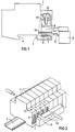
- FIG. 1 shows an installation device of a distribution system illustrates that broken open in the area of the terminal and is partly reproduced in section.
- the busbar and an infeed conductor are lighted with hoses.
- Figure 2 is a distribution system with a mounting rail and snapped-on installation devices with the busbar connected and a connected feeder in perspective reproduced.
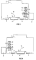
- FIG 3 shows an installation device with two movable holding slides illustrated, the busbar connection, illustrated in a distribution system for wall installation, from the lower access side.
- the installation device 1 of a distribution system according to FIG. 1 can be snapped onto a mounting rail 2 according to FIG. 2.
- the holding slide 3 according to FIG. 1 can be released withdrawn and moved to a stop position will.
- the installation devices 1 can be so-called modular devices or Devices such as miniature circuit breakers, residual current circuit breakers and other devices.
- Serve to connect the busbar 5 Connection elements 6, in a connection opening 7 for connection can be introduced from busbars.
- connection terminal 8 with two superimposed Provide connection openings, the upper connection opening 9 for inserting conductors and the lower connection opening 7 for inserting a connecting element 6 one Busbar 5.
- connection terminal a stationary fixed central web 10 to which a clamping cage 11 move by means of a clamping screw 12 leaves.
- Such terminals are in principle as so-called Elevator clamps known.
- Elevator clamps known.
- connection terminal with respect to its connection opening 7 for connecting busbars around one Extent opens that an installation device at his Holding slide removed from the mounting rail in release can be. That the installation device is raised so far and if necessary can be tilted that it from the connecting element 6 of the busbar 5 above the edge of the mounting rail is released.
- connection terminal with two connection openings is advantageous in order not to need special clamps, to supply ladder to the association of installation devices to be able to feed. It is convenient if the top Connection opening 9 for conductors to be connected above Busbars 5 is formed or arranged. Cheap Positions are facilitated by a fixed central web 10.
- connection opening 7 for busbars leaves which is twice the thickness of connecting elements to be connected Is 6 or more.
- FIG. 2 shows installation devices 1 on a mounting rail 2 arranged, the installation devices on a busbar 5 are connected.
- busbars both common busbars and special designs.
- Feed conductor 13 can in the upper connection opening 9 easily and clearly connected for conductors will.
- the installation devices 1 with correspondingly provided terminals 8 both connected on the lower as well as on the upper access side will.
- Conductor in the connection openings 7, which in itself for busbars are intended to be introduced. That’s it possible with so-called elevator clamps, several large conductors connect, also of different cross-sections.
Landscapes
- Engineering & Computer Science (AREA)
- Power Engineering (AREA)
- Patch Boards (AREA)
Applications Claiming Priority (2)
| Application Number | Priority Date | Filing Date | Title |
|---|---|---|---|
| DE19709812 | 1997-03-10 | ||
| DE19709812 | 1997-03-10 |
Publications (1)
| Publication Number | Publication Date |
|---|---|
| EP0865128A1 true EP0865128A1 (fr) | 1998-09-16 |
Family
ID=7822858
Family Applications (1)
| Application Number | Title | Priority Date | Filing Date |
|---|---|---|---|
| EP98103291A Withdrawn EP0865128A1 (fr) | 1997-03-10 | 1998-02-25 | Système de distribution |
Country Status (1)
| Country | Link |
|---|---|
| EP (1) | EP0865128A1 (fr) |
Cited By (5)
| Publication number | Priority date | Publication date | Assignee | Title |
|---|---|---|---|---|
| DE19859718A1 (de) * | 1998-12-23 | 2000-06-29 | Moeller Gmbh | Stromschienensystem |
| EP1271697A1 (fr) * | 2001-06-06 | 2003-01-02 | Schneider Electric Industries SAS | Borne à vis |
| DE102005052982A1 (de) * | 2005-11-07 | 2007-05-16 | Siemens Ag | Klemmvorrichtung für ein Reiheneinbaugerät |
| EP2849286A1 (fr) | 2013-09-17 | 2015-03-18 | Schneider Electric Industries SAS | Borne à double système de raccordement électrique, en particulier pour un appareil de protection électrique basse tension, et appareil comportant une telle borne |
| DE102021209607A1 (de) | 2021-09-01 | 2023-03-02 | Siemens Aktiengesellschaft | Anschlussklemme und elektrischer Schalter mit solch einer Anschlussklemme |
Citations (8)
| Publication number | Priority date | Publication date | Assignee | Title |
|---|---|---|---|---|
| DE1163937B (de) * | 1962-10-26 | 1964-02-27 | Continental Elektro Ind Ag | Befestigung von elektrischen Geraeten auf Tragschienen |
| DE3314919A1 (de) * | 1983-04-25 | 1984-10-25 | Murr-Elektronik Gmbh, 7155 Oppenweiler | Schraubanschlussklemme |
| FR2612340A1 (fr) * | 1987-03-13 | 1988-09-16 | Merlin Gerin | Borne de raccordement multiple pour appareil electrique modulaire |
| US4790778A (en) * | 1986-04-04 | 1988-12-13 | Siemens Aktiengesellschaft | Equipment quick-connect terminal for connecting electrical conductors to electrical equipment |
| EP0327385A1 (fr) * | 1988-02-05 | 1989-08-09 | Delta Electrical (Holdings) Limited | Un montage pour dispositif électrique |
| DE3922551A1 (de) * | 1989-07-08 | 1991-01-17 | Geyer Gmbh & Co Christian | Vorrichtung zur befestigung eines elektrischen schaltgeraetes |
| EP0454019A1 (fr) * | 1990-04-26 | 1991-10-30 | ABBPATENT GmbH | Borne de raccordement à vis, spécialement pour un appareil de commutation adjacent ou des appareils similaires |
| EP0666626A1 (fr) * | 1994-02-08 | 1995-08-09 | Legrand | Appareil électrique à dispositif de fixation rapide, et procédé pour sa dépose |
-
1998
- 1998-02-25 EP EP98103291A patent/EP0865128A1/fr not_active Withdrawn
Patent Citations (8)
| Publication number | Priority date | Publication date | Assignee | Title |
|---|---|---|---|---|
| DE1163937B (de) * | 1962-10-26 | 1964-02-27 | Continental Elektro Ind Ag | Befestigung von elektrischen Geraeten auf Tragschienen |
| DE3314919A1 (de) * | 1983-04-25 | 1984-10-25 | Murr-Elektronik Gmbh, 7155 Oppenweiler | Schraubanschlussklemme |
| US4790778A (en) * | 1986-04-04 | 1988-12-13 | Siemens Aktiengesellschaft | Equipment quick-connect terminal for connecting electrical conductors to electrical equipment |
| FR2612340A1 (fr) * | 1987-03-13 | 1988-09-16 | Merlin Gerin | Borne de raccordement multiple pour appareil electrique modulaire |
| EP0327385A1 (fr) * | 1988-02-05 | 1989-08-09 | Delta Electrical (Holdings) Limited | Un montage pour dispositif électrique |
| DE3922551A1 (de) * | 1989-07-08 | 1991-01-17 | Geyer Gmbh & Co Christian | Vorrichtung zur befestigung eines elektrischen schaltgeraetes |
| EP0454019A1 (fr) * | 1990-04-26 | 1991-10-30 | ABBPATENT GmbH | Borne de raccordement à vis, spécialement pour un appareil de commutation adjacent ou des appareils similaires |
| EP0666626A1 (fr) * | 1994-02-08 | 1995-08-09 | Legrand | Appareil électrique à dispositif de fixation rapide, et procédé pour sa dépose |
Cited By (6)
| Publication number | Priority date | Publication date | Assignee | Title |
|---|---|---|---|---|
| DE19859718A1 (de) * | 1998-12-23 | 2000-06-29 | Moeller Gmbh | Stromschienensystem |
| EP1271697A1 (fr) * | 2001-06-06 | 2003-01-02 | Schneider Electric Industries SAS | Borne à vis |
| DE102005052982A1 (de) * | 2005-11-07 | 2007-05-16 | Siemens Ag | Klemmvorrichtung für ein Reiheneinbaugerät |
| DE102005052982B4 (de) * | 2005-11-07 | 2007-11-08 | Siemens Ag | Klemmvorrichtung für ein Reiheneinbaugerät |
| EP2849286A1 (fr) | 2013-09-17 | 2015-03-18 | Schneider Electric Industries SAS | Borne à double système de raccordement électrique, en particulier pour un appareil de protection électrique basse tension, et appareil comportant une telle borne |
| DE102021209607A1 (de) | 2021-09-01 | 2023-03-02 | Siemens Aktiengesellschaft | Anschlussklemme und elektrischer Schalter mit solch einer Anschlussklemme |
Similar Documents
| Publication | Publication Date | Title |
|---|---|---|
| DE3805158A1 (de) | Reihenklemme zur zweileiter-stromversorgung von elektrischen oder elektronischen bauelementen, insbesondere initiatoren | |
| DE10237701B4 (de) | Verbindungsklemme für ein-, mehrdrähtige, insbesondere feindrähtige, elektrische Leiter | |
| DE3137117A1 (de) | "schraubklemme" | |
| DE2251020C3 (de) | Anschlußvorrichtung | |
| EP0466043B1 (fr) | Installation de distribution comprenant au moins deux rangées d'appareils électriques de type étroit | |
| EP0865128A1 (fr) | Système de distribution | |
| DE3426212A1 (de) | Schraubklemme fuer elektrische leitungen | |
| DE19918842B4 (de) | Sammelanschluß für elektr. Verteileranlagen | |
| DE3545186C2 (fr) | ||
| EP0762583A2 (fr) | Système de barres omnibus à basse tension | |
| DE4110251C2 (fr) | ||
| DE19751705C2 (de) | Verrasteter Einbaublock | |
| DE69901629T2 (de) | Tragkonsole für Leitungskanäle, insbesondere für elektrische Schaltschränke | |
| DE3601988A1 (de) | Vorrichtung zum abdecken von auf sammelschienen befestigten elektrischen geraeten | |
| DE3302325C1 (de) | Klemmvorrichtung zum Aufsetzen auf Trägerschienen | |
| EP1077509A1 (fr) | Connecteur pour rail électrique | |
| EP0419719B1 (fr) | Unité de raccordement pour raccorder et connecter des câbles électriques | |
| DE19709814B4 (de) | Anreihbares Gerät | |
| DE3507896A1 (de) | Geraeteeinbaudose fuer kabelfuehrungskanaele | |
| EP0865127B1 (fr) | Système de distribution avec un élément de distance | |
| DE2616930C3 (de) | Elektrische Doppel-Reihenklemme | |
| DE4233722A1 (de) | Elektrisches Steckerbauteil | |
| DE60000179T2 (de) | Elektrische Verbindungsanordnung zwischen einer Stromschiene und mindestens einem Leitenden Kabel | |
| DE69508031T2 (de) | Innenraumsystem für einen Schaltschrank und dafür geeigneter Komponentenmodul und Trägermodul | |
| EP0492220A1 (fr) | Distributeur pour raccordement et connexion de fils électriques pour installations de télécommunication |
Legal Events
| Date | Code | Title | Description |
|---|---|---|---|
| PUAI | Public reference made under article 153(3) epc to a published international application that has entered the european phase |
Free format text: ORIGINAL CODE: 0009012 |
|
| AK | Designated contracting states |
Kind code of ref document: A1 Designated state(s): AT DE ES FR GB IT |
|
| AX | Request for extension of the european patent |
Free format text: AL;LT;LV;MK;RO;SI |
|
| AKX | Designation fees paid |
Free format text: AT DE ES FR GB IT |
|
| RBV | Designated contracting states (corrected) |
Designated state(s): AT DE ES FR GB IT |
|
| STAA | Information on the status of an ep patent application or granted ep patent |
Free format text: STATUS: THE APPLICATION IS DEEMED TO BE WITHDRAWN |
|
| 18D | Application deemed to be withdrawn |
Effective date: 19980826 |