EP0865168A2 - Système de communication décentrale - Google Patents
Système de communication décentrale Download PDFInfo
- Publication number
- EP0865168A2 EP0865168A2 EP98103884A EP98103884A EP0865168A2 EP 0865168 A2 EP0865168 A2 EP 0865168A2 EP 98103884 A EP98103884 A EP 98103884A EP 98103884 A EP98103884 A EP 98103884A EP 0865168 A2 EP0865168 A2 EP 0865168A2
- Authority
- EP
- European Patent Office
- Prior art keywords
- communication system
- signal
- terminals
- devices
- signals
- Prior art date
- Legal status (The legal status is an assumption and is not a legal conclusion. Google has not performed a legal analysis and makes no representation as to the accuracy of the status listed.)
- Ceased
Links
- 238000004891 communication Methods 0.000 title claims abstract description 54
- 230000003750 conditioning effect Effects 0.000 claims description 19
- 238000012545 processing Methods 0.000 claims description 19
- 238000000034 method Methods 0.000 claims description 9
- 230000002457 bidirectional effect Effects 0.000 claims description 3
- 230000005540 biological transmission Effects 0.000 claims description 3
- 238000013475 authorization Methods 0.000 claims description 2
- 230000001105 regulatory effect Effects 0.000 claims description 2
- 230000001276 controlling effect Effects 0.000 claims 1
- 238000010438 heat treatment Methods 0.000 description 5
- 230000005855 radiation Effects 0.000 description 2
- 230000006978 adaptation Effects 0.000 description 1
- 230000008878 coupling Effects 0.000 description 1
- 238000010168 coupling process Methods 0.000 description 1
- 238000005859 coupling reaction Methods 0.000 description 1
- 238000013016 damping Methods 0.000 description 1
- 238000012806 monitoring device Methods 0.000 description 1
- 238000012776 robust process Methods 0.000 description 1
- 230000008054 signal transmission Effects 0.000 description 1
- 238000001228 spectrum Methods 0.000 description 1
- 238000012546 transfer Methods 0.000 description 1
Images

Classifications
-
- H—ELECTRICITY
- H04—ELECTRIC COMMUNICATION TECHNIQUE
- H04N—PICTORIAL COMMUNICATION, e.g. TELEVISION
- H04N7/00—Television systems
- H04N7/10—Adaptations for transmission by electrical cable
- H04N7/106—Adaptations for transmission by electrical cable for domestic distribution
-
- H—ELECTRICITY
- H04—ELECTRIC COMMUNICATION TECHNIQUE
- H04B—TRANSMISSION
- H04B1/00—Details of transmission systems, not covered by a single one of groups H04B3/00 - H04B13/00; Details of transmission systems not characterised by the medium used for transmission
- H04B1/06—Receivers
- H04B1/16—Circuits
- H04B1/20—Circuits for coupling gramophone pick-up, recorder output, or microphone to receiver
- H04B1/207—Circuits for coupling gramophone pick-up, recorder output, or microphone to receiver with an audio or audio/video bus for signal distribution
-
- H—ELECTRICITY
- H04—ELECTRIC COMMUNICATION TECHNIQUE
- H04L—TRANSMISSION OF DIGITAL INFORMATION, e.g. TELEGRAPHIC COMMUNICATION
- H04L12/00—Data switching networks
- H04L12/28—Data switching networks characterised by path configuration, e.g. LAN [Local Area Networks] or WAN [Wide Area Networks]
- H04L12/2803—Home automation networks
- H04L12/2838—Distribution of signals within a home automation network, e.g. involving splitting/multiplexing signals to/from different paths
-
- H—ELECTRICITY
- H04—ELECTRIC COMMUNICATION TECHNIQUE
- H04L—TRANSMISSION OF DIGITAL INFORMATION, e.g. TELEGRAPHIC COMMUNICATION
- H04L12/00—Data switching networks
- H04L12/28—Data switching networks characterised by path configuration, e.g. LAN [Local Area Networks] or WAN [Wide Area Networks]
- H04L12/2803—Home automation networks
- H04L2012/284—Home automation networks characterised by the type of medium used
- H04L2012/2841—Wireless
Definitions
- the invention relates to a communication system with at least two independent signal sources.
- Such a communication system is, for example, a so-called IN-House "network.
- the communication system is used to transmit information to various end devices within a house, such as a television set, heating, room surveillance and between them.
- the invention has for its object a communication system specify that access without additional wiring enables different services within a house.
- the basic concept of such a communication system is therefore its decentralized structure.
- In this Air interface are both the logical control channel and the Find control channels as well as the respective data channels again.
- a continuous control channel can affect the intelligence of the network the different devices are distributed. Each device can do this itself decide whether channel access is possible or not.
- the signal sources the external service provider, such as TV services, Telephone services, broadcasting services, etc. are directly with the respective Terminals, such as TV, radio reception equipment or Telephone terminal connected.
- the implementation takes place on the for example, an interface designed as a wireless in-house connection to the end device without additional effort for feeding to one central location.
- connection With a bidirectional connection like this for example, is required in any case for telephone services compared to a central structure of the communication system, i.e. in the case of an indirect connection, for example to a first terminal via a central to a second terminal, a big advantage in terms of to the required bandwidth. Compared to the proposed direct In this case, the connection requires twice the bandwidth.
- An advantageous low-cost connection between neighboring ones Terminal equipment is that for the connection between stationary or quasi-stationary terminals an infrared connection is provided.
- the exposure in the form of high-frequency radiation can thereby be reduced to a minimum that the signal conditioning devices and the terminals have means for regulating the transmission power.
- a sufficient for existing and upcoming requirements Configuration of the communication system is achieved in that the Signal conditioning devices for conditioning analog and / or digital audio and / or video signals, in particular radio, television and / or Telephone signals are provided.
- the respective data transfer between the signal sinks and the end devices takes place in that the signal processing devices and the Terminal devices each have a modem for access to external services and Adaptation to the respective communication between Have signal processing device and terminal.
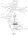
- the communication system shown in Fig. 1 has a first Signal source 1, which is provided for the distribution of television signals 17 which are received via cable, satellite or terrestrial.
- the signals 17 of the signal source 1 become a signal processing device 4 supplied, the signal conditioning device 4 is used to distribute the Signals 17 to terminals 2, 3, 5.
- the terminals 2, 3, 5 are in the in Fig. 1st illustrated embodiment, a TV receiver 2 with a Receiving device 2a, a screen 3 and a radio receiving device 5 with a receiving part 5a.
- a radio interface 27 is provided between TV reception equipment 2 and radio receiver 5 is also a radio interface 27 is provided.
- the transmission of signals 17 between the signal conditioning device 4 and the television or Radio receivers 2, 5 take place wirelessly via radio interfaces 19, 20.
- the signals received by the radio receiver 5, can further radio interfaces 21, 22, for example as Infrared interfaces are formed, distributed to speakers 6a, 6b will.
- the communication system shown in Fig. 1 has furthermore a second signal source 10 for receiving Telephone signals 18 on.
- the telephone signals 18 become a second Signal processing device 11 supplied via radio interfaces 23 ... 26 can be connected to end devices 12 .. 16.
- a connection between stationary 15 and portable personal computer 15 is over another Interface 32 possible.
- the communication system shown in Fig. 1 also shows a connection option shown in dashed lines between the signal conditioning devices 4 and 11, whereby a Connection of the different signal sources is possible.
- a coupling of the TV receiving device is also via a radio interface 28 2 to the second signal source 10.
- the communication system shown in Fig. 1 is based on a decentralized structure of signal sources 1, 10, i.e. the signal sources 1, 10 or the corresponding signal processing devices 4, 11 are with the respective end devices 2, 3, 5 - 12 ... 15 directly via the wireless in-house connection connected.
- Such a decentralized structure of the Communication system has the advantage that all services of the signal sources 1, 10 distributed directly at the respective location where these are available can be without being central to a data stream must be summarized. This can be an additional Cabling effort to an otherwise necessary central station be avoided.
- Signal source 1 is, for example a data source that provides television signals over the Connection line 17 supplied to the signal conditioning device 4 will.
- the signal conditioning device 4 is used for decoding the TV signals supplied by the signal source 1 and for the radiation of the appropriately prepared television signals to the respective terminals 2, 3, 5. Through the wireless connection of the terminals 2, 3, 5 to the Signal conditioning device 4 is therefore not required, for example an additional wiring effort for a residential unit.
- the connection of the terminals 2, 3, 5 to the signal processing device 4 takes place via the air interfaces 19, 20.
- the Signal source 10 telephone signals supplied via the connecting line 18 from the second signal processing device 11 to the one with this connectable terminals 12 ... 15 transmitted.
- Via connecting line 19 or by direct connection to the respective Signal conditioning device it is also possible that certain Terminal devices, such as the PC 15 with several signal sources 1, 10 communicates.
- Fig. 1 shown communication system terminals that on none Access service, such as that shown in Fig. 1 Speakers 6a, 6b and the printer 16 is the case. Beyond that also provided terminals that use only a single service, such as this is the case for example with the telephone 12, 13. Overall arises through the communication system shown in Fig. 1 a flexible Connection to the corresponding signal sources 1, 10. So that a direct parallel access of the different end devices to the different ones Signal sources 1, 10 are possible, the Signal conditioning devices 4, 11 and the terminals 2, 3, 5; 12 ... 15 corresponding modems that address the registration or deregistration to serve.
- a channel access method such as for example CDMA, TDMA or FDMA or a combination of these Procedure used.
- CDMA Code Division Multiple Access
- TDMA Time Division Multiple Access
- FDMA Frequency Division Multiple Access
- this method offers one increased security in relation to data protection problems.
- About the Radio interface 28 between the TV receiver 2 and Signal conditioning device 11 for the second signal source 10 is for example, receiving faxes or accessing Communication services, such as the Internet, are possible.
- the house or housing unit to be supplied consists of Clear R1, R2, R3, R4.
- room R1 there is a connection 1 to Reception of television signals, for example via cable, satellite or via terrestrial reception options.
- connection 10 is provided, for example as an ISDN telephone connection is trained. Via these decentrally arranged connections 1, 10 the entire residential unit R1 ... R4 is supplied. So are in Room R4 a TV receiver unit 2 with monitor or TV receiver 3 available. Are in room R4 in addition, two speakers 6a, 6b, for example via wireless Infrared connection to the television 3 are coupled.
- the transmitting devices e.g. the decoder for digital TV 2 directly with the respective Receiving devices, e.g. connected to the television 3.
- This is done right at the place of origin for every service that is for the residents of the Housing unit is provided, the implementation on the wireless In-house connection.
- a complex implementation in a central Data stream that supplies several services centrally, for example, is thus dispensable.
- An additional cabling effort in the cabling of centrally planned structures would also be necessary superfluous.
- the communication system shown in Fig. 2 has in addition, a very high flexibility, since a structure in small Steps towards a complex system according to the respective Requirements is possible without much effort.
- the signal source 1 for receiving television programs access both the receiving device 2 and the PC 15.
- the signal processing device 4 for the respective signal sources 1, 10 take place where the signal sources for Are available or where the services are needed in close proximity.
- the respective transmission power / reception power of the Signal conditioning devices 4, 10 or the respective terminals 2, 3; 12, 15 can thus be reduced to a minimum.
- the Communication system a corresponding reception power regulation (Power Control) on.
- This receive / transmit power regulation is such trained that the receiver when placed directly next to the transmitter is set to minimum reception power and at maximum distance or additional damping, for example through walls, its full Delivers receiving power.
- the communication system also communication with others Services, for example via radio communication service such as GSM or DAB services that can be integrated.
- FIG. 3 shows another embodiment of a local and wireless Communication system.
- the communication system shown in Fig. 3 consists of signal sources 1, 10 with respective Signal conditioning devices 4, 11. Die Signal processing devices, 4, 11 are for processing television or Telephone signals provided.
- the signal processing devices 4, 11 are connected to a device 2 via radio interfaces 43, 44, that as an interface to a television set 3 and more Radio interfaces 45, 46 to a heating control device 41 and one Safety control device 42 is used.
- the Heater control device 41 is connected to the heating center 40 coupled while the safety control device 42 with for example, signal generators arranged on windows, doors, etc. connected is.
Landscapes
- Engineering & Computer Science (AREA)
- Multimedia (AREA)
- Signal Processing (AREA)
- Computer Networks & Wireless Communication (AREA)
- Automation & Control Theory (AREA)
- Mobile Radio Communication Systems (AREA)
- Small-Scale Networks (AREA)
- Selective Calling Equipment (AREA)
Applications Claiming Priority (2)
| Application Number | Priority Date | Filing Date | Title |
|---|---|---|---|
| DE1997110169 DE19710169A1 (de) | 1997-03-12 | 1997-03-12 | Dezentrales Kommunikationssystem |
| DE19710169 | 1997-03-12 |
Publications (2)
| Publication Number | Publication Date |
|---|---|
| EP0865168A2 true EP0865168A2 (fr) | 1998-09-16 |
| EP0865168A3 EP0865168A3 (fr) | 2003-09-03 |
Family
ID=7823097
Family Applications (1)
| Application Number | Title | Priority Date | Filing Date |
|---|---|---|---|
| EP98103884A Ceased EP0865168A3 (fr) | 1997-03-12 | 1998-03-05 | Système de communication décentrale |
Country Status (2)
| Country | Link |
|---|---|
| EP (1) | EP0865168A3 (fr) |
| DE (1) | DE19710169A1 (fr) |
Cited By (2)
| Publication number | Priority date | Publication date | Assignee | Title |
|---|---|---|---|---|
| WO2002003691A1 (fr) * | 2000-06-30 | 2002-01-10 | Fast Tv Server Ag | Procede pour mettre des informations a disposition sur un televiseur |
| US7274831B2 (en) | 2003-04-03 | 2007-09-25 | Microsoft Corporation | High quality anti-aliasing |
Citations (1)
| Publication number | Priority date | Publication date | Assignee | Title |
|---|---|---|---|---|
| US5101499A (en) * | 1987-09-15 | 1992-03-31 | Jerry R. Iggulden | Television local wireless transmission and control |
Family Cites Families (10)
| Publication number | Priority date | Publication date | Assignee | Title |
|---|---|---|---|---|
| DE4001810C2 (de) * | 1990-01-23 | 1996-02-08 | Loewe Opta Gmbh | Energiesparschaltung in einer mobilen Vorrichtung zur drahtlosen Kommunikation |
| JPH05284203A (ja) * | 1990-04-05 | 1993-10-29 | Texas Instr Inc <Ti> | 電気通信に準拠した通話のためのユーザー・インタフェースの方法とシステム |
| DE4227914A1 (de) * | 1992-08-22 | 1994-02-24 | Sensys Ag | Infrarot-Telefonanlage |
| US5325423A (en) * | 1992-11-13 | 1994-06-28 | Multimedia Systems Corporation | Interactive multimedia communication system |
| CA2137383C (fr) * | 1994-01-03 | 2001-02-13 | Gary Len Griffith | Dispositif de commutation pour terminaux de communication sans fil, avec fonctions de commutation pour terminaux cables |
| US5459779A (en) * | 1994-02-25 | 1995-10-17 | At&T Ipm Corp. | Method for switching telephone calls to information service providers |
| US5537467A (en) * | 1994-08-23 | 1996-07-16 | Bell Communications Research, Inc. | Method for forwarding a call to a temporarily utilized portable telephone |
| DE19514616A1 (de) * | 1995-04-25 | 1996-10-31 | Sel Alcatel Ag | Kommunikationssystem mit hierarchischer Serverstruktur |
| US5610910A (en) * | 1995-08-17 | 1997-03-11 | Northern Telecom Limited | Access to telecommunications networks in multi-service environment |
| DE19538842A1 (de) * | 1995-10-19 | 1997-04-24 | Walter Dipl Ing Siepmann | Mobiltelefon |
-
1997
- 1997-03-12 DE DE1997110169 patent/DE19710169A1/de not_active Ceased
-
1998
- 1998-03-05 EP EP98103884A patent/EP0865168A3/fr not_active Ceased
Patent Citations (1)
| Publication number | Priority date | Publication date | Assignee | Title |
|---|---|---|---|---|
| US5101499A (en) * | 1987-09-15 | 1992-03-31 | Jerry R. Iggulden | Television local wireless transmission and control |
Non-Patent Citations (1)
| Title |
|---|
| CHOW P.S.; CIOFFI J.M.: "A MULTI-DROP IN-HOUSE ADSL DISTRIBUTION NETWORK", IEEE INTERNATIONAL CONFERENCE, 1 May 1994 (1994-05-01), USA, XP010126562 * |
Cited By (4)
| Publication number | Priority date | Publication date | Assignee | Title |
|---|---|---|---|---|
| WO2002003691A1 (fr) * | 2000-06-30 | 2002-01-10 | Fast Tv Server Ag | Procede pour mettre des informations a disposition sur un televiseur |
| DE10031121A1 (de) * | 2000-06-30 | 2002-01-17 | Fast Tv Server Ag | Verfahren zum Bereitstellen von Information auf einem Fernsehgerät |
| DE10031121B4 (de) * | 2000-06-30 | 2006-10-05 | Sony United Kingdom Ltd., Brooklands | Verfahren zum Bereitstellen von Information auf einem Fernsehgerät |
| US7274831B2 (en) | 2003-04-03 | 2007-09-25 | Microsoft Corporation | High quality anti-aliasing |
Also Published As
| Publication number | Publication date |
|---|---|
| DE19710169A1 (de) | 1998-09-17 |
| EP0865168A3 (fr) | 2003-09-03 |
Similar Documents
| Publication | Publication Date | Title |
|---|---|---|
| DE69631372T2 (de) | Leckkabelübertragungssystem und entsprechende Ausrüstung für eine Teilnehmereinrichtung | |
| DE69130642T2 (de) | Kabelfernseh-hochfrequenz-teilnehmerdatenübertragungsgerät und radiofrequenz-rückübertragungsverfahren | |
| DE19702350B4 (de) | Zentralknoten-Konverter zur Verbindung mit einem Anschluss eines Haus-Netzwerks, das mit einem Koaxialkabel verbunden ist und Verfahren zur Kommunikation | |
| DE19848899A1 (de) | Personalcomputer-basierter Set-Top-Konverter für Fernsehdienste | |
| EP1719367B1 (fr) | Utilisation multiple d'une interface standardisee dans un dispositif | |
| DE69901546T2 (de) | Universelles signalverteilsystem | |
| EP0731619B1 (fr) | Système de communication à large bande et son procédé | |
| EP0965202A2 (fr) | Dispositif et procede de communication sans fil en norme dect | |
| EP0865168A2 (fr) | Système de communication décentrale | |
| DE2917978A1 (de) | Kabelkommunikationssystem | |
| EP1025657B1 (fr) | Systeme de transmission d'informations fonde sur la transmission combinee ondes courtes-satellite | |
| EP2154884B1 (fr) | Prise d'antenne | |
| EP0933884B1 (fr) | Adaptation de la puisssance de transmission en particulier pour la communication domestique sans fil | |
| EP0059786B1 (fr) | Prise de contact d'antenne | |
| EP1182872B1 (fr) | Système de communication | |
| EP0419713A1 (fr) | Module d'interface pour un interface de ligne bus | |
| DE69614072T2 (de) | Kabelnetzwerksystem für Videoverteilung und bidirektionale Datenübertragung, mit Freqenzumsetzung im Rückkanal | |
| DE10005763B4 (de) | Antennensignal-Hausverteilnetz für die Übertragung von Fernseh- und/oder Rundfunkprogrammen | |
| DE60036743T2 (de) | Übertragung Daten mit geringer Priorität über ein Satellit durch Verwendung der unbenutzte Kapazität des Transponders | |
| DE19641897C2 (de) | System zur Übertragung und Verteilung von Fernsehsignalen mit dynamischer Zuweisung der Übertragungskapazität | |
| DE19806685A1 (de) | Interaktive Breitbandmedien | |
| EP0706293A2 (fr) | Réseau domestique pour la distribution de signaux vidéo et/ou audio pour la transmission bidirectionelle additionelle des signaux relatifs aux abonnés | |
| DE10103521C1 (de) | Steuersystem | |
| EP0883263A2 (fr) | Dispositif pour la transmission de signaux numériques | |
| DE4435767A1 (de) | Breitbandinformationssystem für Verteildienste und interaktive Dienste |
Legal Events
| Date | Code | Title | Description |
|---|---|---|---|
| PUAI | Public reference made under article 153(3) epc to a published international application that has entered the european phase |
Free format text: ORIGINAL CODE: 0009012 |
|
| AK | Designated contracting states |
Kind code of ref document: A2 Designated state(s): AT BE CH DE DK ES FI FR GB GR IE IT LI LU MC NL PT SE |
|
| AX | Request for extension of the european patent |
Free format text: AL;LT;LV;MK;RO;SI |
|
| RAP1 | Party data changed (applicant data changed or rights of an application transferred) |
Owner name: GRUNDIG AKTIENGESELLSCHAFT |
|
| PUAL | Search report despatched |
Free format text: ORIGINAL CODE: 0009013 |
|
| RIC1 | Information provided on ipc code assigned before grant |
Ipc: 7H 04N 7/10 B Ipc: 7H 04H 1/10 B Ipc: 7H 04M 11/00 B Ipc: 7H 04L 12/28 B Ipc: 7H 04B 1/20 A |
|
| AK | Designated contracting states |
Kind code of ref document: A3 Designated state(s): AT BE CH DE DK ES FI FR GB GR IE IT LI LU MC NL PT SE |
|
| AX | Request for extension of the european patent |
Extension state: AL LT LV MK RO SI |
|
| 17P | Request for examination filed |
Effective date: 20031029 |
|
| 17Q | First examination report despatched |
Effective date: 20031222 |
|
| AKX | Designation fees paid |
Designated state(s): AT BE CH DE DK FR GB IT LI NL |
|
| RAP1 | Party data changed (applicant data changed or rights of an application transferred) |
Owner name: GRUNDIG MULTIMEDIA B.V. |
|
| STAA | Information on the status of an ep patent application or granted ep patent |
Free format text: STATUS: THE APPLICATION HAS BEEN REFUSED |
|
| 18R | Application refused |
Effective date: 20051112 |