EP0865181A2 - Procédé pour la réduction d'interférences cocanaux - Google Patents
Procédé pour la réduction d'interférences cocanaux Download PDFInfo
- Publication number
- EP0865181A2 EP0865181A2 EP98104287A EP98104287A EP0865181A2 EP 0865181 A2 EP0865181 A2 EP 0865181A2 EP 98104287 A EP98104287 A EP 98104287A EP 98104287 A EP98104287 A EP 98104287A EP 0865181 A2 EP0865181 A2 EP 0865181A2
- Authority
- EP
- European Patent Office
- Prior art keywords
- orthogonal
- conversion
- matrix
- orthogonal matrix
- modulation
- Prior art date
- Legal status (The legal status is an assumption and is not a legal conclusion. Google has not performed a legal analysis and makes no representation as to the accuracy of the status listed.)
- Granted
Links
Images


Classifications
-
- H—ELECTRICITY
- H04—ELECTRIC COMMUNICATION TECHNIQUE
- H04L—TRANSMISSION OF DIGITAL INFORMATION, e.g. TELEGRAPHIC COMMUNICATION
- H04L23/00—Apparatus or local circuits for systems other than those covered by groups H04L15/00 - H04L21/00
- H04L23/02—Apparatus or local circuits for systems other than those covered by groups H04L15/00 - H04L21/00 adapted for orthogonal signalling
-
- H—ELECTRICITY
- H04—ELECTRIC COMMUNICATION TECHNIQUE
- H04L—TRANSMISSION OF DIGITAL INFORMATION, e.g. TELEGRAPHIC COMMUNICATION
- H04L5/00—Arrangements affording multiple use of the transmission path
- H04L5/0001—Arrangements for dividing the transmission path
- H04L5/0003—Two-dimensional division
- H04L5/0005—Time-frequency
- H04L5/0007—Time-frequency the frequencies being orthogonal, e.g. OFDM(A) or DMT
Definitions
- This invention relates to a communication method, a transmitter and a receiver, and more particularly, is applicable to radio communication system such as a portable telephone system or the like.
- an area for providing communication service is divided into cells having a desired size and a base station is set as a fixed radio station in the cell.
- the portable telephone device as a mobile radio station is installed in the cell so that the portable telephone device as a fixed radio station is constituted to be engaged in communication with the base station in the cell in which the portable telephone device is present.
- the interference problem of an electronic wave is avoided by using a channel of frequency which is different between cells (this is simply referred to as a channel).
- the channel is only changed at random so that it is not necessarily possible to avoid that the channel becomes the same between adjacent cells. Thus, it is feared that the timing becomes the same. In the case where the same channel is used, there might arise an interference problem in the same manner as the prior art.
- the sending signal CB which is sent by the portable telephone device 2B reaches the base station 3A.
- the sending signal CB which reaches the base station 3A becomes an interference wave (so-called hindrance wave) with respect to the sending signal CA which is sent to the base station 3A.
- the signal level of the sending signal CA is larger than the interference wave I, and no considerable problem is generated in normal cases.
- the base station 3A receives the interference wave I by mistake instead of the sending signal CA from the portable telephone device 2A.
- the signal series transmitted by the portable telephone device 2B is restored, and the communication content of the other person is leaked with the result that a situation which is not preferable as a radio communication system might arise.
- the interference wave I is not demodulated.
- an object of this invention is to provide a communication method which is capable of avoiding restoring the signal series which is sent in other communication by mistake even when the same channel is used in the other communication, and is to provide a transmitter and receiver which use the communication method.
- the orthogonal conversion is performed by multiplying an orthogonal matrix which is different for each communication to signal series which is sent, and the signal series to which the orthogonal conversion is performed is sent by using the predetermined channel.
- the signal series before the orthogonal conversion is restored by multiplying the inverse matrix of the orthogonal matrix which is used on the sending side of the communication partner to the received signal series.
- the signal series is multiplied with the orthogonal matrix which is different for each communication and transmitted, and at a receiving side, the received signal series is multiplied with an inverse matrix of the orthogonal matrix used at a transmitting side of the communication partner, so that the signal series before orthogonal conversion is restored. Therefore, even when another communication is performed and received by using the same channel, since the orthogonal matrix used for the orthogonal conversion differs from one communication to another, inverse orthogonal conversion cannot be attained for one communication even if an inverse matrix for another communication is multiplied, thereby signal series sent in another communication being not restored.
- Fig. 2 reference numerals 5A, 5B denote the portable telephone device respectively.
- Reference numeral 6A and 6B denote the base station to which the present invention is applied.
- the portable telephone device 5A uses the predetermined channel to be engaged in radio communication with the base station 6A in the cell 1A.
- the same channel is used in the adjacent cell 1B so that the portable telephone device 5B is engaged in radio communication with the base station 6B.
- QPSK modulation Quadratture Phase Shift Keying; Four Phase Transition Modulation
- the signal series of the modulated sending signal are defined as x (A) 1 , X (A) 2 , X (A) 3 , ... ... X (A) k-1 , X (A) k , X (A) k+1 , ... ... and X (B) 1 , X (B) 2 , X (B) 3 , ... ... X (B) k-1 , X (B) k , X (B) k+1 , ... ....
- the grouped sending signal series x (A) k , ... ... x (A) k+N and a predetermined Nth normal orthogonal matrix M A are multiplied in order as shown in the following equation.
- the grouped sending signal series x (B) k , ... ... X (B) k+N and the predetermined Nth normal orthogonal matrix M B are multiplied in order for each group as shown in the following equation.
- the Nth normal orthogonal matrix M B which is used in the portable telephone device 5B and the Nth normal orthogonal matrix M A which is used in the portable telephone device 5A are matrixes which are completely different from each other.
- the sending signal CA sent by the portable telephone device 5A reaches, but the sending signal CB sent by the portable telephone device 5B also reaches depending on the situation.
- the sending signal CB from the portable telephone device 5B acts as an interference wave I.
- the signal level of the sending signal CB is large as compared with the sending signal CA from the portable telephone device 5A, trouble is caused to communication with the portable telephone device 5A.
- the base station 6A it is not recognized that the signal is a sending signal from either of the portable telephone devices 5A or 5B so that it is feared that the sending signal CB from the portable telephone device 5B is received by mistake.
- the orthogonal matrix which is different for each communication at the sending side is multiplied with the signal series.
- the received signal series is multiplied with the inverse matrix of the orthogonal matrix which is used on the sending side (namely, the communication partner of its own station) so that the original signal series before the orthogonal conversion is restored.
- the leakage problem is avoided when the sending signal CB of the portable telephone device 5B is received by the base station 6A.
- the leakage problem can be also avoided even when the base station 6B receives the sending signal CA of the portable telephone device 5A.
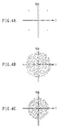
- the phase state is present at a position where the phase state becomes ⁇ /4, 3 ⁇ /4, 5 ⁇ /4 or 7 ⁇ /4.
- the base station 6A does not recognize that the signal series is either the sending signal from the communication partner or the interference wave, the demodulation processing is performed as in the normal receiving processing.
- the phase state is not brought back to the original state so that the phase state becomes a random state. Consequently, even when the signal series shown in Fig. 4C is QPSK demodulated, the sending data from the portable telephone device 5B is not restored. Consequently, the leakage of the data sent by the other communication can be avoided, and the generation of the undesirable state as a radio communication system can be avoided.
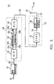
- the portable telephone device 5A (or 5B) has the transmitter 10 shown in Fig. 5.
- This transmitter 10 roughly comprises a QPSK modulation circuit 11, an orthogonal conversion part 12, and a sending part 13 so that the sent data S1 supplied via the predetermined noise processing circuit or the like is input to the QPSK modulation circuit 11 in the beginning.
- the QPSK modulation circuit 11 converts the sent data S1 into a sending signal series S2 of the phase data by performing the QPSK modulation processing on the sent data S1 so that the sending signal series S2 is output to a serial/parallel conversion circuit (S/P) 14 of the orthogonal conversion part 12.
- the serial/parallel conversion circuit 14 is a circuit for grouping N groups of the sending signal series S2 so that the sent signal series which is input is N parallel signal by dividing the input signal series S2 into N signals and the resulting parallel signal series ST 1 through ST N is output to an orthogonal conversion circuit 15.
- the orthogonal conversion circuit 15 is a circuit for adding an orthogonal conversion to the sending signal series by using a predetermined Nth normal orthogonal matrix.
- the parallel signal series ST 1 through ST N are defined as one group and Nth normal orthogonal matrix is multiplied in order, and each group of signal series ST 1 through ST N are subjected to an orthogonal conversion.
- the orthogonal conversion circuit 15 searches for a matrix which is completely different from the Nth normal orthogonal matrix which is used in the other communication, and the matrix is not used for the orthogonal conversion, and a matrix which is selected at random from the Nth normal orthogonal matrixes which are present in plurality.
- this orthogonal conversion circuit 15 obtains a matrix ostensibly different from the matrix which is used in the other communication by selecting at random a matrix out of the Nth normal orthogonal matrixes which are present in plurality so that the matrix selection processing is simplified.
- N Nth Walsh vectors are prepared as the Nth diagonal vector whose vector components comprise two values.
- the orthogonal conversion circuit 15 gives a random phase rotation to this Nth Walsh vector respectively so that the Nth random normal orthogonal matrix is generated by combining the random phase rotation.
- a random phase rotation is given to the Walsh vectors W 1 , W 2 , ... ... W N by multiplying random phase rotation components e jZ1 , e jZ2 , ... ... e jZN (here Z1 through ZN denote phase rotation angles) to Nth Walsh vectors W 1 , W 2 , ... ... W N . Then, 1/ ⁇ N is multiplied so that a random Nth normal orthogonal matrix M is generated.
- W 1 T , W 2 T , ... ... W N T is what is vector placed so as to have a vector component in a line direction of the Walsh vectors W 1 , W 2 , ... ... W N having vector component in the row direction.
- the orthogonal conversion circuit 15 selects the Nth normal orthogonal matrix and multiplies it to the parallel signal series ST 1 through ST N so that the orthogonal conversion is added to the signal series ST 1 , through ST N .
- the resulting parallel signal series ST 1 ' through ST N ' are output to a parallel/serial conversion circuit (P/S) 16.
- the parallel/serial conversion circuit 16 is a circuit for collecting grouped sending signal series into one group by converting a parallel signal into a serial signal so that the parallel signal series ST 1 ' through ST N ' which are input are converted into a serial signal series S3, which is output to a reverse Fourier conversion circuit (IFFT) 17 at the sending part 13.
- the reverse Fourier conversion circuit 17 dissipates and overlaps the signal series S3 with a plurality of multiple carriers having a different frequencies by adding a reverse Fourier conversion to the signal series S3. Then the resulting sending signal S4 is output to a high frequency circuit 18.
- the high frequency circuit 18 converts this sending signal S4 into a predetermined channel of sending signal S5 in frequency.
- the sending signal is sent via an antenna 19.
- the high frequency circuit 18 changes at random the channel of the sending signal S5 for each of the predetermined timing (so-called frequency hopping is performed). As a consequence, the usage efficiency of the frequency is improved while avoiding the situation that the channel becomes the same as the other communication.
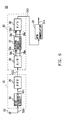
- the base station 6A (or 6B) has a receiver 20 as shown in Fig. 6.
- This receiver 20 roughly comprises a receiving part 21, an orthogonal conversion part 22, and a QPSK demodulation circuit 29.
- the signal S10 received via the antenna 23 is input to a high frequency circuit 24 of the receiving part 21.
- the high frequency circuit 24 amplifies the sending signal S10 to a predetermined power, and at the same time, the received signal S10 is converted into a received signal S11 of a base band, and the received signal is output to the Fourier conversion circuit (FFT) 25.
- FFT Fourier conversion circuit
- the Fourier conversion circuit 25 extracts a signal series S12 which is dissipated and overlapped with the a plurality of multiple carriers by adding the Fourier conversion to the receiving signal S11 and the extracted signal is output to a serial/parallel conversion circuit (S/P) 26 of the diagonal reverse conversion part 22.
- the serial/parallel conversion circuit 26 is a circuit for dividing the signal series S12 into groups comprising N signal series, and the circuit converts the signal series into N parallel data by dividing input signal series S12 into groups comprising N signal series and the resulting parallel signal series SR 1 through SR N are output to a diagonal reverse conversion circuit 27.
- the diagonal reverse conversion circuit 27 is a circuit for performing diagonal reverse conversion by using an inverse matrix of Nth normal orthogonal matrix which is used by the orthogonal conversion circuit 15 of the communication partner.
- the diagonal reverse conversion circuit adds the diagonal reverse conversion for each group with respect to the signal series SR 1 through SR N by multiplying the inverse matrix in order by defining the input parallel signal series SR 1 through SR N as one group.
- the resulting signal series SR 1 ' through SR N ' is output to a parallel/serial conversion circuit (P/S) 28.
- P/S parallel/serial conversion circuit
- the diagonal reverse conversion circuit 27 recognizes Nth normal orthogonal matrix which is used on the sending side by receiving processing or the like of the control signal, for example, at the time of the start of the communication.
- the parallel/serial conversion circuit 28 is a circuit for collecting received signal series which is grouped into one group by converting the parallel signal into a serial signal.
- the input parallel signal series SR 1 ' through SR N ' are converted into a serial signal series S13.
- this signal series S13 is output to a QPSK modulation circuit 29.
- the QPSK modulation circuit 29 restores the received data S14 from the signal series S13 which is phase data by performing a predetermined demodulation processing such as, for example, diagonal delay wave detection to the QPSK modulated signal series S13. In this manner, the received data S14 which is the same as the sent data S1 on the sending side is restored on the receiving side.
- a predetermined demodulation processing such as, for example, diagonal delay wave detection
- bi-direction communication is performed between the portable telephone device 5A (or 5B) and the base station 6A (or 6B) so that the portable telephone device 5A (or 5B) is provided with a receiver which is approximately the same as the aforementioned receiver 20.
- the base station 6A (or 6B) is provided with a transmitter which is approximately similar to the aforementioned transmitter 10.
- the orthogonal conversion is applied to the signal series by multiplying the Nth normal orthogonal matrix which is different for each communication to the signal series which is QPSK modulated at the time of sending the signal, and the orthogonally converted signal series is sent.
- the diagonal reverse conversion is applied to the signal series by multiplying the inverse matrix of the Nth normal orthogonal matrix which is used on the sending side of the communication partner to the signal series which has been received and the signal series which is subjected to the reverse conversion is subjected to QPSK demodulation.
- the signal series x (A) n (n 1, 2, 3, ...
- the base station 6A receives the sending signal CA from the portable telephone device 5A which is a communication partner
- the base station 6A receives the sending signal CB from the portable telephone device 5B
- the inverse matrix M A -1 is not an inverse matrix of the orthogonal matrix M B which is used on the sending side.
- this radio communication system multiplies the orthogonal matrix which is different for each communication to the signal series on the sending side and sends it, while the system multiplies the inverse matrix of the orthogonal matrix which is used at the sending side of the communication partner to the received signal series on the receiving side and the original signal series is restored with the result that the same channel is used in the other communication.
- the orthogonal matrix which is used at the sending time is different from the other communication so that the diagonal reverse conversion is not realized by multiplying the inverse matrix, and the signal series which is sent in the other communication is not restored.
- the leakage of the sent data which is sent in the other communication can be avoided in advance.
- a completely different Nth normal orthogonal matrix is not selected by examining the Nth normal orthogonal matrix which is used in the other communication at the time of selecting the Nth normal orthogonal matrix in the orthogonal conversion circuit 15.
- the matrix which is different from the matrix which is used in the other communication is selected by selecting the orthogonal matrix at random out of the Nth normal orthogonal matrixes which are present in plurality. Consequently, a process of examining the matrix which is used in the other communication becomes unnecessary so that a selection processing of the orthogonal matrix can be simplified.
- an orthogonal matrix to be used is assigned to each base station in advance, and the terminal station may select the orthogonal matrix to be used in accordance with the base station with which the communication is performed.
- a plurality of orthogonal matrixes are not prepared in advance at the time of selecting the orthogonal matrix.
- N Nth Walsh vectors are prepared in advance, and random phase rotation is given to the Walsh vectors W 1 , W 2 , ... ... W N so that Nth normal orthogonal matrix is obtained by combining the Walsh vectors W 1 , W 2 , ... ... W N . Consequently, the calculation part for calculating the normal orthogonal matrix is constituted with addition and subtraction processing, and at the same time, a memory for memorizing a plurality of orthogonal matrixes becomes unnecessary and the normal orthogonal matrix can be calculated with a simple structure.
- Nth normal orthogonal matrix which is calculated by using the Walsh vector is shown here as a reference.
- M A e jZA
- M B e jZB
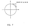
- the normal orthogonal matrixes M A and M B when used, it means that the signal series having a phase state which is set to ⁇ /4, 3 ⁇ /4, 5 ⁇ /4 or 7 ⁇ /4 on the complex surface is rotated in a predetermined direction by phase rotation angles ZA and ZB.
- M A -1 M B e j(ZB-ZA)
- a vector shown in the following equation is used as the line displacement vectors W 1 T and W 2 T of the second Walsh vectors W 1 and W 2 .
- the sending side multiplies and sends the orthogonal matrix which is different from each other for each communication to the signal matrix
- the receiving side restores the original signal series before the orthogonal conversion by multiplying the inverse matrix of the orthogonal matrix used by the sending side of the communication partner to the received signal series with the result that the same channel is used in the other communication. Even when the same channel is received, the mistaken restoration of the signal series which is sent in the other communication can be avoided in advance, and the leakage of the sent data which is sent in the other communication can be avoided in advance.
- N Nth Walsh vectors are prepared at the time of selecting the orthogonal matrix, respective random phase rotation is given to the Walsh vector, and the Walsh vector to which the phase rotation is given is combined thereby generating more random orthogonal matrix.
- the present invention is not limited thereto. The same advantage as described above can be obtained by generating more random orthogonal matrix by arranging each vector component of the predetermined orthogonal matrix at random.
- QPSK modulation is used as the modulation method for the sent data.
- the present invention is not limited thereto.
- Other modulation method such as BPSK modulation (Binary Phase Shift Keying), 16 QAM modulation (16 Quadrature Amplitude Modulation) may be used.
- the present invention is applied to a radio communication system of the communication method such that the signal series is dissipated to a plurality of multiple carriers and is overlapped to send the resulting sending signal to the predetermined channel by converting the frequency, and at the same time, the channel of the sending signal is changed at random for each predetermined timing.
- the present invention is not limited thereto.
- the present invention may be applied to the radio communication system of the other communication.
- the so-called same channel interference is generated in which the same channel is used to perform at least two or more communications so that two or more communication electronic waves interfere with each other.
- the orthogonal matrix which is different for each communication is multiplied to the signal series and sent, and the receiving side restores the signal series before the orthogonal conversion by multiplying the inverse matrix of the orthogonal matrix which is used on the sending side of the communication partner to the received signal series.
- the other communication is performed by using the same channel so that even when the signal series is received the diagonal reverse conversion is not realized even by multiplying the inverse matrix to the signal series because the orthogonal matrix which is used in the orthogonal conversion is different from the other communication, and the signal series which is used in the other communication is not restored.
Landscapes
- Engineering & Computer Science (AREA)
- Signal Processing (AREA)
- Computer Networks & Wireless Communication (AREA)
- Mobile Radio Communication Systems (AREA)
- Digital Transmission Methods That Use Modulated Carrier Waves (AREA)
- Noise Elimination (AREA)
Applications Claiming Priority (3)
| Application Number | Priority Date | Filing Date | Title |
|---|---|---|---|
| JP54486/97 | 1997-03-10 | ||
| JP5448697 | 1997-03-10 | ||
| JP05448697A JP3724676B2 (ja) | 1997-03-10 | 1997-03-10 | 通信方法及び送信装置並びに受信装置 |
Publications (3)
| Publication Number | Publication Date |
|---|---|
| EP0865181A2 true EP0865181A2 (fr) | 1998-09-16 |
| EP0865181A3 EP0865181A3 (fr) | 2001-08-16 |
| EP0865181B1 EP0865181B1 (fr) | 2004-10-13 |
Family
ID=12971985
Family Applications (1)
| Application Number | Title | Priority Date | Filing Date |
|---|---|---|---|
| EP98104287A Expired - Lifetime EP0865181B1 (fr) | 1997-03-10 | 1998-03-10 | Procédé pour la réduction d'interférences cocanaux |
Country Status (9)
| Country | Link |
|---|---|
| US (1) | US6292663B1 (fr) |
| EP (1) | EP0865181B1 (fr) |
| JP (1) | JP3724676B2 (fr) |
| KR (1) | KR100560602B1 (fr) |
| CN (1) | CN1162017C (fr) |
| AU (1) | AU746332B2 (fr) |
| DE (1) | DE69826913T2 (fr) |
| ES (1) | ES2226018T3 (fr) |
| SG (1) | SG81922A1 (fr) |
Cited By (4)
| Publication number | Priority date | Publication date | Assignee | Title |
|---|---|---|---|---|
| EP1065849A1 (fr) * | 1999-06-29 | 2001-01-03 | Commissariat A L'energie Atomique | Procédé de transmission à modulation/démodulation multi-MOK |
| EP0966133A3 (fr) * | 1998-06-15 | 2002-07-24 | Sony International (Europe) GmbH | Transformations orthogonaux pour la réduction d'interférence dans des systèmes multiporteurs |
| EP1317809A4 (fr) * | 2000-08-09 | 2005-05-18 | Avway Com Inc | Procede et systeme d'integration steganographique de bits d'information dans des signaux sources |
| EP1264434B1 (fr) * | 1999-12-22 | 2006-09-13 | Deutsche Telekom AG | Procede et circuit pour la transmission securisee dans des systemes de transmission numeriques |
Families Citing this family (4)
| Publication number | Priority date | Publication date | Assignee | Title |
|---|---|---|---|---|
| JPH1168696A (ja) * | 1997-08-19 | 1999-03-09 | Sony Corp | 通信方法及び送信装置及び受信装置並びにセルラー無線通信システム |
| JP4765054B2 (ja) * | 2004-05-19 | 2011-09-07 | 国立大学法人山口大学 | アナログ符号化システム |
| JP4607007B2 (ja) * | 2005-12-28 | 2011-01-05 | Kddi株式会社 | マルチキャリア信号伝送システム、無線基地局装置、無線端末装置及びマルチキャリア信号伝送方法 |
| JP4641013B2 (ja) * | 2006-09-04 | 2011-03-02 | 日本電信電話株式会社 | 光通信システム |
Family Cites Families (16)
| Publication number | Priority date | Publication date | Assignee | Title |
|---|---|---|---|---|
| US3715508A (en) * | 1967-09-15 | 1973-02-06 | Ibm | Switching circuits employing orthogonal and quasi-orthogonal pseudo-random code sequences |
| US3833767A (en) * | 1971-06-23 | 1974-09-03 | A Wolf | Speech compression system |
| DE2523828C2 (de) * | 1975-05-30 | 1982-08-12 | TE KA DE Felten & Guilleaume Fernmeldeanlagen GmbH, 8500 Nürnberg | Verfahren zur Verschleierung von Sprachsignalen mit Hilfe orthogonaler Matrizen |
| US4379205A (en) * | 1979-06-22 | 1983-04-05 | Bell Telephone Laboratories, Incorporated | Analog signal scrambling system |
| DE3511430A1 (de) * | 1985-03-29 | 1986-10-02 | Philips Patentverwaltung Gmbh, 2000 Hamburg | Verfahren zur synchronisierung der empfangseinrichtungen in einem digitalen multiplex-uebertragungssystem |
| US5103459B1 (en) * | 1990-06-25 | 1999-07-06 | Qualcomm Inc | System and method for generating signal waveforms in a cdma cellular telephone system |
| US5204874A (en) * | 1991-08-28 | 1993-04-20 | Motorola, Inc. | Method and apparatus for using orthogonal coding in a communication system |
| US5367516A (en) * | 1993-03-17 | 1994-11-22 | Miller William J | Method and apparatus for signal transmission and reception |
| GB9413481D0 (en) * | 1994-07-05 | 1994-08-24 | British Broadcasting Corp | Improvements to digital transmission systems |
| US5623485A (en) * | 1995-02-21 | 1997-04-22 | Lucent Technologies Inc. | Dual mode code division multiple access communication system and method |
| US6356555B1 (en) * | 1995-08-25 | 2002-03-12 | Terayon Communications Systems, Inc. | Apparatus and method for digital data transmission using orthogonal codes |
| US5793759A (en) * | 1995-08-25 | 1998-08-11 | Terayon Corporation | Apparatus and method for digital data transmission over video cable using orthogonal cyclic codes |
| US5768269A (en) * | 1995-08-25 | 1998-06-16 | Terayon Corporation | Apparatus and method for establishing frame synchronization in distributed digital data communication systems |
| US5978413A (en) * | 1995-08-28 | 1999-11-02 | Bender; Paul E. | Method and system for processing a plurality of multiple access transmissions |
| KR0159201B1 (ko) * | 1995-12-06 | 1998-12-01 | 양승택 | Cdma 시스템에서의 동기식 이중 채널 qpsk 변복조 장치 및 그 변복조방법 |
| JPH1013918A (ja) * | 1996-06-19 | 1998-01-16 | Toshiba Corp | 符号分割多元接続方式を採用した移動通信システムとその無線通信装置 |
-
1997
- 1997-03-10 JP JP05448697A patent/JP3724676B2/ja not_active Expired - Lifetime
-
1998
- 1998-03-05 US US09/035,293 patent/US6292663B1/en not_active Expired - Lifetime
- 1998-03-05 AU AU57390/98A patent/AU746332B2/en not_active Expired
- 1998-03-09 KR KR1019980007776A patent/KR100560602B1/ko not_active Expired - Lifetime
- 1998-03-10 EP EP98104287A patent/EP0865181B1/fr not_active Expired - Lifetime
- 1998-03-10 CN CNB981082947A patent/CN1162017C/zh not_active Expired - Lifetime
- 1998-03-10 ES ES98104287T patent/ES2226018T3/es not_active Expired - Lifetime
- 1998-03-10 DE DE69826913T patent/DE69826913T2/de not_active Expired - Lifetime
- 1998-03-10 SG SG9800531A patent/SG81922A1/en unknown
Cited By (8)
| Publication number | Priority date | Publication date | Assignee | Title |
|---|---|---|---|---|
| EP0966133A3 (fr) * | 1998-06-15 | 2002-07-24 | Sony International (Europe) GmbH | Transformations orthogonaux pour la réduction d'interférence dans des systèmes multiporteurs |
| US6631168B2 (en) | 1998-06-15 | 2003-10-07 | Sony International (Europe) Gmbh | Generating matrices to be used for the random orthogonal transformation of blocks of data in a transmission chain |
| EP1065849A1 (fr) * | 1999-06-29 | 2001-01-03 | Commissariat A L'energie Atomique | Procédé de transmission à modulation/démodulation multi-MOK |
| FR2795894A1 (fr) * | 1999-06-29 | 2001-01-05 | Commissariat Energie Atomique | Procede de transmission a modulation/demodulation multi-mak, emetteur et recepteur correspondants |
| US7327778B1 (en) | 1999-06-29 | 2008-02-05 | Commissariat A L'energie Atomique | Multi-mok modulation/demodulation transmission process, corresponding transmitter and receiver |
| US7668225B2 (en) | 1999-06-29 | 2010-02-23 | Commissariat A L'energie Atomique | Multi-MOK modulation/demodulation transmission process, corresponding transmitter and receiver |
| EP1264434B1 (fr) * | 1999-12-22 | 2006-09-13 | Deutsche Telekom AG | Procede et circuit pour la transmission securisee dans des systemes de transmission numeriques |
| EP1317809A4 (fr) * | 2000-08-09 | 2005-05-18 | Avway Com Inc | Procede et systeme d'integration steganographique de bits d'information dans des signaux sources |
Also Published As
| Publication number | Publication date |
|---|---|
| KR100560602B1 (ko) | 2006-07-27 |
| JP3724676B2 (ja) | 2005-12-07 |
| US6292663B1 (en) | 2001-09-18 |
| SG81922A1 (en) | 2001-07-24 |
| EP0865181B1 (fr) | 2004-10-13 |
| DE69826913T2 (de) | 2005-10-13 |
| CN1162017C (zh) | 2004-08-11 |
| CN1199313A (zh) | 1998-11-18 |
| AU5739098A (en) | 1998-09-10 |
| JPH10257012A (ja) | 1998-09-25 |
| AU746332B2 (en) | 2002-04-18 |
| ES2226018T3 (es) | 2005-03-16 |
| DE69826913D1 (de) | 2004-11-18 |
| KR19980080044A (ko) | 1998-11-25 |
| EP0865181A3 (fr) | 2001-08-16 |
Similar Documents
| Publication | Publication Date | Title |
|---|---|---|
| EP1168653B1 (fr) | Désétalement/démodulation de signaux à spectre étalé en séquence directe | |
| KR100911077B1 (ko) | 무선 통신 장치 및 무선 통신 방법 | |
| JP5139508B2 (ja) | スペクトル拡散通信システムおよび方法 | |
| US6031865A (en) | Rapidly decorrelating spreading sequences for DS-CDMA transceivers | |
| US5784403A (en) | Spread spectrum correlation using saw device | |
| EP1047218A2 (fr) | Procédé et système de diversité pour la liaison descendante dans un système CDMA utilisant des codes de Walsh | |
| EP0839412B1 (fr) | Procede et dispositif d'estimation de canaux a spectre etale | |
| US6823021B1 (en) | Method and apparatus for space division multiple access receiver | |
| EP0898400A2 (fr) | Procédé de communication , dispositives de transmission et de reception et système de communication à radio cellulaire | |
| KR100438240B1 (ko) | 데이터 전송 장치 및 데이터 전송 방법 | |
| EP0865181A2 (fr) | Procédé pour la réduction d'interférences cocanaux | |
| EP1205036B1 (fr) | Generateur de signal et decodeur | |
| JPH08251117A (ja) | マルチキャリア伝送システム及びマルチキャリア伝送方法 | |
| US8170079B2 (en) | Code division multiple access signaling for modulated reflector technology | |
| CN110278041B (zh) | 差分混沌键控调制解调方法、装置、系统及可读存储介质 | |
| JP2003198500A (ja) | スペクトル拡散通信システムおよび方法 | |
| KR100250022B1 (ko) | 직교 변조기에 제공된 피크 클립핑 회로 및 동상 및 직교신호의 피크 레벨을 클립핑하는 방법 | |
| US20080267311A1 (en) | Radio communication method, radio transmission apparatus and receiving apparatus | |
| KR101038079B1 (ko) | 무선센서네트웍에서 m-1-1 협력통신과 osoc-ss를 사용한 데이터전송 방법 및 장치 | |
| Rahman et al. | Post-detection diversity combining for non-coherent MT-CDMA system in a Rician fading channel | |
| Li et al. | Performance analysis of multi-tier asynchronous M-PSK DS/CDMA systems with a nonlinear amplifier | |
| KR20040078316A (ko) | 이동통신 시스템의 수신기에서 다중 경로로 전송된데이터의 처리 장치 및 방법 |
Legal Events
| Date | Code | Title | Description |
|---|---|---|---|
| PUAI | Public reference made under article 153(3) epc to a published international application that has entered the european phase |
Free format text: ORIGINAL CODE: 0009012 |
|
| AK | Designated contracting states |
Kind code of ref document: A2 Designated state(s): DE ES FI FR GB IT NL SE |
|
| AX | Request for extension of the european patent |
Free format text: AL;LT;LV;MK;RO;SI |
|
| PUAL | Search report despatched |
Free format text: ORIGINAL CODE: 0009013 |
|
| AK | Designated contracting states |
Kind code of ref document: A3 Designated state(s): AT BE CH DE DK ES FI FR GB GR IE IT LI LU MC NL PT SE |
|
| AX | Request for extension of the european patent |
Free format text: AL;LT;LV;MK;RO;SI |
|
| RIC1 | Information provided on ipc code assigned before grant |
Free format text: 7H 04K 1/02 A, 7H 04L 23/02 B |
|
| 17P | Request for examination filed |
Effective date: 20011218 |
|
| AKX | Designation fees paid |
Free format text: DE ES FI FR GB IT NL SE |
|
| 17Q | First examination report despatched |
Effective date: 20020604 |
|
| GRAP | Despatch of communication of intention to grant a patent |
Free format text: ORIGINAL CODE: EPIDOSNIGR1 |
|
| GRAS | Grant fee paid |
Free format text: ORIGINAL CODE: EPIDOSNIGR3 |
|
| GRAA | (expected) grant |
Free format text: ORIGINAL CODE: 0009210 |
|
| AK | Designated contracting states |
Kind code of ref document: B1 Designated state(s): DE ES FI FR GB IT NL SE |
|
| REG | Reference to a national code |
Ref country code: GB Ref legal event code: FG4D |
|
| REG | Reference to a national code |
Ref country code: SE Ref legal event code: TRGR |
|
| REF | Corresponds to: |
Ref document number: 69826913 Country of ref document: DE Date of ref document: 20041118 Kind code of ref document: P |
|
| REG | Reference to a national code |
Ref country code: ES Ref legal event code: FG2A Ref document number: 2226018 Country of ref document: ES Kind code of ref document: T3 |
|
| PLBE | No opposition filed within time limit |
Free format text: ORIGINAL CODE: 0009261 |
|
| STAA | Information on the status of an ep patent application or granted ep patent |
Free format text: STATUS: NO OPPOSITION FILED WITHIN TIME LIMIT |
|
| ET | Fr: translation filed | ||
| 26N | No opposition filed |
Effective date: 20050714 |
|
| REG | Reference to a national code |
Ref country code: GB Ref legal event code: 746 Effective date: 20091130 |
|
| REG | Reference to a national code |
Ref country code: FR Ref legal event code: PLFP Year of fee payment: 19 |
|
| REG | Reference to a national code |
Ref country code: FR Ref legal event code: PLFP Year of fee payment: 20 |
|
| PGFP | Annual fee paid to national office [announced via postgrant information from national office to epo] |
Ref country code: DE Payment date: 20170322 Year of fee payment: 20 Ref country code: SE Payment date: 20170321 Year of fee payment: 20 Ref country code: FI Payment date: 20170313 Year of fee payment: 20 Ref country code: FR Payment date: 20170322 Year of fee payment: 20 Ref country code: NL Payment date: 20170321 Year of fee payment: 20 |
|
| PGFP | Annual fee paid to national office [announced via postgrant information from national office to epo] |
Ref country code: GB Payment date: 20170322 Year of fee payment: 20 |
|
| PGFP | Annual fee paid to national office [announced via postgrant information from national office to epo] |
Ref country code: ES Payment date: 20170315 Year of fee payment: 20 |
|
| PGFP | Annual fee paid to national office [announced via postgrant information from national office to epo] |
Ref country code: IT Payment date: 20170323 Year of fee payment: 20 |
|
| REG | Reference to a national code |
Ref country code: DE Ref legal event code: R071 Ref document number: 69826913 Country of ref document: DE |
|
| REG | Reference to a national code |
Ref country code: NL Ref legal event code: MK Effective date: 20180309 |
|
| REG | Reference to a national code |
Ref country code: GB Ref legal event code: PE20 Expiry date: 20180309 |
|
| PG25 | Lapsed in a contracting state [announced via postgrant information from national office to epo] |
Ref country code: GB Free format text: LAPSE BECAUSE OF EXPIRATION OF PROTECTION Effective date: 20180309 |
|
| REG | Reference to a national code |
Ref country code: SE Ref legal event code: EUG |
|
| REG | Reference to a national code |
Ref country code: ES Ref legal event code: FD2A Effective date: 20200904 |
|
| PG25 | Lapsed in a contracting state [announced via postgrant information from national office to epo] |
Ref country code: ES Free format text: LAPSE BECAUSE OF EXPIRATION OF PROTECTION Effective date: 20180311 |