EP0865221B1 - Verfahren und Vorrichtung zue Erzeugung von Wegprofilen bei Radiowellenausbreitungen - Google Patents
Verfahren und Vorrichtung zue Erzeugung von Wegprofilen bei Radiowellenausbreitungen Download PDFInfo
- Publication number
- EP0865221B1 EP0865221B1 EP98850034A EP98850034A EP0865221B1 EP 0865221 B1 EP0865221 B1 EP 0865221B1 EP 98850034 A EP98850034 A EP 98850034A EP 98850034 A EP98850034 A EP 98850034A EP 0865221 B1 EP0865221 B1 EP 0865221B1
- Authority
- EP
- European Patent Office
- Prior art keywords
- path profile
- path
- adjacent
- profile
- primary
- Prior art date
- Legal status (The legal status is an assumption and is not a legal conclusion. Google has not performed a legal analysis and makes no representation as to the accuracy of the status listed.)
- Expired - Lifetime
Links
- 238000000034 method Methods 0.000 title claims abstract description 36
- 230000001131 transforming effect Effects 0.000 claims 2
- 238000000926 separation method Methods 0.000 description 6
- 238000012876 topography Methods 0.000 description 6
- 238000004364 calculation method Methods 0.000 description 4
- 230000009466 transformation Effects 0.000 description 4
- 230000008901 benefit Effects 0.000 description 2
- 230000008569 process Effects 0.000 description 2
- 230000002411 adverse Effects 0.000 description 1
- 230000000903 blocking effect Effects 0.000 description 1
- 230000007812 deficiency Effects 0.000 description 1
- 230000007246 mechanism Effects 0.000 description 1
- 230000009467 reduction Effects 0.000 description 1
- 230000035945 sensitivity Effects 0.000 description 1
Images

Classifications
-
- H—ELECTRICITY
- H04—ELECTRIC COMMUNICATION TECHNIQUE
- H04W—WIRELESS COMMUNICATION NETWORKS
- H04W16/00—Network planning, e.g. coverage or traffic planning tools; Network deployment, e.g. resource partitioning or cells structures
- H04W16/18—Network planning tools
- H04W16/20—Network planning tools for indoor coverage or short range network deployment
-
- H—ELECTRICITY
- H04—ELECTRIC COMMUNICATION TECHNIQUE
- H04B—TRANSMISSION
- H04B17/00—Monitoring; Testing
- H04B17/30—Monitoring; Testing of propagation channels
- H04B17/391—Modelling the propagation channel
- H04B17/3911—Fading models or fading generators
-
- H—ELECTRICITY
- H04—ELECTRIC COMMUNICATION TECHNIQUE
- H04W—WIRELESS COMMUNICATION NETWORKS
- H04W16/00—Network planning, e.g. coverage or traffic planning tools; Network deployment, e.g. resource partitioning or cells structures
- H04W16/18—Network planning tools
Definitions
- the present invention relates to a method and a device for generation of path profiles for use in radio wave propagation planning, including point-to-point, point-to-multipoint and area coverage applications, and which are particularly useful in urban and suburban areas.
- path profiles are today usually generated between specified endpoint coordinates, using raster format topography data, such as elevation, clutter, obstacles, etc.
- the quality of a generated path profile depends heavily on the quality of the input data sets, as well as the algorithms used.
- the main sources for uncertainties can be listed as follows:
- topography data can be improved by means of simply increasing the resolution. This is always a good solution, but normally rather expensive.
- the vertical resolution of the topography data can be taken into account in the predictions. This will normally produce a more pessimistic result, which can be compared to the result obtained in a standard manner.
- Path profile generation algorithms can be made to use refined interpolation methods. This will normally be a good solution for non-urban areas, but will not eliminate the problems for urban areas, where obstacles tend to be discrete with respect to normal raster resolutions.
- a simple interpolation method is linear interpolation between the two closest raster points. This method is not very well suited for urban areas. Another method is selecting the highest of the two closest raster points. This method is better suited for urban areas, although constantly pessimistic. Yet another method is linear interpolation in the plane spanned by the three closest raster points. This method is not very well suited for urban areas.
- IEEE TRANSACTIONS ON ANTENNAS AND PROPAGATION, Volume 42, No. 5, May 1994, Rainer Grosskopf, 'Prediction of Urban Propagation Loss' pages 658-665, XP002900186 describes a method of calculating models for multipath propagation due to signal reflections in urban areas. In particular, a path loss is calculated in order to predict the received power of a transmitted radio signal, for mobile reception.
- This object is obtained by means of generating multiple path profiles whereby a broader view of the path in question is provided. This will improve the sensitivity to adjacent obstacles, which is especially useful in urban areas.
- the inventive method and device for generating a path profile for radio wave propagation in a raster with height data can be summarised as follows:
- the path profile generation algorithm considers only the intersection of the raster with the straight line between the endpoints. In reality, the whole of the first Fresnel zone should be considered for possible obstacles. This can be achieved by generating a set of adjacent path profiles, in addition to the primary one. Potential obstructions missed out in the primary path profile will be caught by one of the adjacent ones. This approach is hence useful wherever adjacent obstacles are present, and especially in urban and suburban environments.
- the multiple path profiles can be utilised as follows:
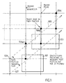
- fig. 1 a general view from above of an urban area, is shown.
- the reference numerals 101 and 103 denote buildings, the dashed line 105 a primary path profile, and the dashed line 107 an adjacent path profile.
- the grid in the figure 1 illustrates the raster, and the intersections between the raster lines are associated with data indicating the coordinates of the raster points and the height at the individual raster points.
- the primary path profile is taken from a point 109 along the line 105. If the closest raster data points, i.e. the points 106a, 106b and 106c, respectively, along this line 105 are used as prediction data, no obstacles are predicted to be present in the radio propagation path. If, on the other hand, more advanced prediction methods are employed such as interpolation between neighbouring raster data points the prediction might be improved, but will still be poor due to the discrete heights of the urban area.
- a better way would therefore be to generate adjacent path profiles, in particular parallel path profiles, covering the entire first Fresnel zone of the path and to use the maximum values within the first Fresnel zone as prediction values.
- Such a method would, however, be over-pessimistic, and a more advanced and accurate prediction method is therefore desired.
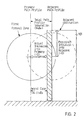
- the building 101 translated into an obstruction 113 in the primary path profile is shown.
- the prediction would be a total blocking of the first Fresnel zone of the radio wave propagation path.
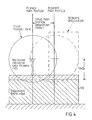
- Another, much more accurate, prediction is obtained if the following transformation is performed. If an obstacle is detected along any of the adjacent path profiles, the distance between the adjacent path profile and the primary path profile is derived. The wall of the building is then presumed to end somewhere between the adjacent path and the primary path. A preferred such presumption is half way between the detected obstacle and the nearest path profile.
- the original building 101 is transformed into an equivalent obstacle 111, but which is located on the primary path profile.
- the equivalent obstacle 111 will be identical to the presumed building wall with regard to the significant radio wave propagation characteristics.
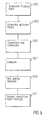
- fig. 5 is a flow chart illustrating the steps performed in a system using the method described herein.
- a primary path profile is generated.
- a number of adjacent path profiles are generated.
- the number of adjacent path profiles can be determined according to several different methods as described below.
- the obstacles found in the adjacent path profiles are then transformed according to some suitable algorithm, such as some of the algorithms described below, and the largest obstacles are translated onto the primary path profile.
- the transformation and translation is performed in a block 505.
- each of the transformed and translated obstacles found in the primary path profiles is compared to the corresponding obstacle, i.e. the one located equally far from the path profile endpoints, in the primary profile, and if any of the translated and transformed obstacle is larger than the corresponding obstacle in the primary path profile, the transformed and translated obstacle is set to replace the corresponding obstacle in the primary path profile. This replacement is performed in a block 509.
- the resulting path profile which is constituted by the largest obstacles in the primary path profile and the largest transformed and translated obstacles of the adjacent path profiles, is output for use in the radio wave propagation planning.
- the endpoint coordinates of any adjacent path profile are determined from the discrete endpoint coordinates of the primary, offset by an integer multiple of the current raster separation, oriented along either or both of the cardinal axes of the grid.
- This alternative requires the radio wave propagation planning system to have specific knowledge of the inner mechanisms of the topography subsystem concerning the handling of path profile endpoint coordinates.
- This alternative uses the path profile generation routine to round off the specified endpoint coordinates to the nearest raster points, and is therefore more desirable than the previous.
- one method is to move obstacles unchanged into the primary path profile.
- This technique assumes that the adjacent obstacle does in reality obstruct also the primary path profile, and in exactly the same way as it obstructs the adjacent path profile, but that it was missed out in the path profile generation process due to insufficient raster resolution or simplifications in the algorithm used.
- the obstacle in the adjacent path profile is simply moved to the primary path profile, without changing the obstacle height in any way.
- Another method is to Transform obstacles into equivalent knife-edges in the primary path profile. This technique assumes that the adjacent obstacle in reality only obstructs a portion of the first Fresnel zone of the primary path profile, and should rightly be considered as a knife-edge protruding into the Fresnel zone from one of the sides, and not, as normally is the case, from below.
- the obstacle in the adjacent path profile is first transformed to an equivalent knife-edge, before it is moved to the primary path profile.
- the obstacle height will be set so that the equivalent knife-edge vertical intrusion into the first Fresnel zone equals the original side-ways intrusion of the actual obstacle.
- This approach is best suited for catching adjacent obstacles located far from the primary path profile, and should normally be used for N>>1, or when the first Fresnel zone radius is much larger than the raster resolution.
Landscapes
- Engineering & Computer Science (AREA)
- Computer Networks & Wireless Communication (AREA)
- Signal Processing (AREA)
- Physics & Mathematics (AREA)
- Electromagnetism (AREA)
- Mobile Radio Communication Systems (AREA)
- Near-Field Transmission Systems (AREA)
- Burglar Alarm Systems (AREA)
- Variable-Direction Aerials And Aerial Arrays (AREA)
- Processing Or Creating Images (AREA)
- Compositions Of Oxide Ceramics (AREA)
Claims (6)
- Verfahren zum Erzeugen eines Pfadprofils für Funkwellenausbreitung in einem Raster mit Höhendaten, umfassend den Schritt des Erzeugens eines primären Pfadprofils (105), gekennzeichnet durch die weiteren Schritte:Erzeugen zumindest eines angrenzenden Pfadprofils (107) in einem Abstand vom primären Pfadprofil (105),Umwandeln von, im angrenzenden Pfadprofil (107) gefundenen Hindernissen gemäß einem bestimmten Algorithmus, undÜbersetzen der umgewandelten Hindernisse auf das primäre Pfadprofil (105), um ein resultierendes verschmolzenes Pfadprofil zu erzeugen.
- Verfahren gemäß Anspruch 1, dadurch gekennzeichnet, dass mehrere angrenzende Pfadprofile in Abständen, die einer verwendeten Rasterauflösung entsprechen, erzeugt werden.
- Verfahren gemäß Anspruch 1 oder 2, dadurch gekennzeichnet, dass das im größten Abstand zu einem primären Pfadprofil gelegene, angrenzende Pfadprofil in einem Abstand erzeugt wird, der im wesentlichen dem Radius der ersten Fresnelzone im Mittelpunkt desselben entspricht.
- Vorrichtung zum Erzeugen eines Pfadprofils für Funkwellenausbreitung in einem Raster mit Höhendaten, wobei die Vorrichtung Mittel zum Erzeugen eines primären Pfadprofils (105) aufweist, gekennzeichnet durch:Mittel zum Erzeugen zumindest eines angrenzenden Pfadprofils (107) in einem Abstand vom primären Pfadprofil (105),Mittel zum Umwandeln von, im angrenzenden Pfadprofil (107) gefundenen Hindernissen gemäß einem bestimmten Algorithmus, undMittel zum Übersetzen der umgewandelten Hindernisse auf das primäre Pfadprofil (105), um ein resultierendes verschmolzenes Pfadprofil zu erzeugen.
- Vorrichtung gemäß Anspruch 4, gekennzeichnet durchMittel zum Erzeugen mehrerer angrenzender Pfadprofile in Abständen, die einer verwendeten Rasterauflösung entsprechen.
- Vorrichtung gemäß Anspruch 4 oder 5, gekennzeichnet durchMittel zum Erzeugen des im größten Abstand zu einem primären Pfadprofil gelegenen angrenzenden Pfadprofils in einem Abstand, der im wesentlichen dem Radius der ersten Fresnelzone im Mittelpunkt desselben entspricht.
Applications Claiming Priority (2)
| Application Number | Priority Date | Filing Date | Title |
|---|---|---|---|
| SE9700927A SE521001C2 (sv) | 1997-03-14 | 1997-03-14 | Förfarande och anordning för anordning för siktlinjesprofilgenerering |
| SE9700927 | 1997-03-14 |
Publications (2)
| Publication Number | Publication Date |
|---|---|
| EP0865221A1 EP0865221A1 (de) | 1998-09-16 |
| EP0865221B1 true EP0865221B1 (de) | 2005-05-25 |
Family
ID=20406156
Family Applications (1)
| Application Number | Title | Priority Date | Filing Date |
|---|---|---|---|
| EP98850034A Expired - Lifetime EP0865221B1 (de) | 1997-03-14 | 1998-03-12 | Verfahren und Vorrichtung zue Erzeugung von Wegprofilen bei Radiowellenausbreitungen |
Country Status (7)
| Country | Link |
|---|---|
| US (1) | US6047238A (de) |
| EP (1) | EP0865221B1 (de) |
| AT (1) | ATE296526T1 (de) |
| CA (1) | CA2232016A1 (de) |
| DE (1) | DE69830266T2 (de) |
| PL (1) | PL325326A1 (de) |
| SE (1) | SE521001C2 (de) |
Families Citing this family (6)
| Publication number | Priority date | Publication date | Assignee | Title |
|---|---|---|---|---|
| US5901214A (en) * | 1996-06-10 | 1999-05-04 | Murex Securities, Ltd. | One number intelligent call processing system |
| WO2004003705A2 (en) | 2002-06-27 | 2004-01-08 | Small World Productions, Inc. | System and method for locating and notifying a user of a person, place or thing having attributes matching the user's stated prefernces |
| US7840218B2 (en) * | 2004-02-05 | 2010-11-23 | Telecom Itala S.p.A. | Method and system for radio coverage planning with local double grid approach |
| EP1714512B1 (de) * | 2004-02-05 | 2008-04-09 | Telecom Italia S.p.A. | Verfahren und system zur funkversorgungsplanung mit einem mehrfachauflösungsprofil |
| DE102012100653A1 (de) * | 2012-01-26 | 2013-08-01 | Endress + Hauser Process Solutions Ag | Verfahren zur Bestimmung der Qualität einer Verbindung zwischen zwei Teilnehmern eines drahtlosen Maschennetzwerks in einer |
| JP7347130B2 (ja) * | 2019-11-05 | 2023-09-20 | 中国電力株式会社 | フレネルゾーンの検査方法とそれに用いられる障害物検出システム |
Family Cites Families (2)
| Publication number | Priority date | Publication date | Assignee | Title |
|---|---|---|---|---|
| BR7606976A (pt) * | 1976-10-15 | 1977-05-03 | Camargo L De | Dispositivo de acao ondulatoria para radio frequencias |
| US5815813A (en) * | 1995-11-24 | 1998-09-29 | Northern Telecom Limited | Multipath tolerant cellular communication system and method |
-
1997
- 1997-03-14 SE SE9700927A patent/SE521001C2/sv not_active IP Right Cessation
-
1998
- 1998-03-03 US US09/033,672 patent/US6047238A/en not_active Expired - Fee Related
- 1998-03-12 EP EP98850034A patent/EP0865221B1/de not_active Expired - Lifetime
- 1998-03-12 DE DE69830266T patent/DE69830266T2/de not_active Expired - Lifetime
- 1998-03-12 AT AT98850034T patent/ATE296526T1/de not_active IP Right Cessation
- 1998-03-13 PL PL98325326A patent/PL325326A1/xx unknown
- 1998-03-13 CA CA002232016A patent/CA2232016A1/en not_active Abandoned
Also Published As
| Publication number | Publication date |
|---|---|
| SE9700927L (sv) | 1998-09-15 |
| DE69830266T2 (de) | 2005-11-10 |
| US6047238A (en) | 2000-04-04 |
| DE69830266D1 (de) | 2005-06-30 |
| SE521001C2 (sv) | 2003-09-23 |
| SE9700927D0 (sv) | 1997-03-14 |
| EP0865221A1 (de) | 1998-09-16 |
| CA2232016A1 (en) | 1998-09-14 |
| PL325326A1 (en) | 1998-09-28 |
| ATE296526T1 (de) | 2005-06-15 |
Similar Documents
| Publication | Publication Date | Title |
|---|---|---|
| Neskovic et al. | Modern approaches in modeling of mobile radio systems propagation environment | |
| FI114671B (fi) | Menetelmä langattoman viestintäjärjestelmän suunnittelemiseksi | |
| US7171210B2 (en) | Method and apparatus for network planning | |
| KR20010041385A (ko) | 무선 통신 시스템 서비스 영역내의 가입자 위치를 추정하기 위한 방법 및 시스템 | |
| CN115412926B (zh) | 基站站址规划方法、基站站址规划系统、设备及介质 | |
| JPH09153867A (ja) | 電波伝搬シミュレータ | |
| CN115356748B (zh) | 基于激光雷达观测结果提取大气污染信息的方法与系统 | |
| EP0865221A1 (de) | Verfahren und Vorrichtung zue Erzeugung von Wegprofilen bei Radiowellenausbreitungen | |
| Russell et al. | A deterministic approach to predicting microwave diffraction by buildings for microcellular systems | |
| Maurer et al. | A novel approach in the determination of visible surfaces in 3D vector geometries for ray-optical wave propagation modelling | |
| CN119070885B (zh) | 低轨通信卫星星地通信质量评估方法、装置、设备和介质 | |
| Kreuzgruber et al. | Prediction of indoor radio propagation with the ray splitting model including edge diffraction and rough surfaces | |
| EP0944968B1 (de) | Verfahren und vorrichtung zur feldstärkeschätzung | |
| Borenović et al. | Space partitioning strategies for indoor WLAN positioning with cascade-connected ANN structures | |
| CN115664876A (zh) | 云广播控制方法、装置、终端及存储介质 | |
| Tang et al. | Dynamic viewshed analysis based on the digital elevation model: dynamic range proximity-direction-elevation reference line | |
| Saunders et al. | Physical–statistical methods for determining state transition probabilities in mobile‐satellite channel models | |
| Storsaeter et al. | A GIS-based tool for optimizing C-ITS communication infrastructure | |
| CN121208752B (zh) | 定位方法及相关设备 | |
| Kimpe et al. | Computerized indoor radio channel estimation using ray tracing | |
| US20240345200A1 (en) | Modeling of multi-path reflection for generating wireless connectivity heatmaps for physical environments | |
| Baala et al. | Toward environment indicators to evaluate WLAN-based indoor positioning system | |
| CN121357496A (zh) | 室内区域定位方法、装置及计算机可读存储介质 | |
| CN120108198A (zh) | 车型识别方法和电子设备 | |
| Fang et al. | CNN Credibility-Driven 5G-IMU Fusion Localization Optimization for Indoor Environments with High-Dynamic Pedestrian Scenarios |
Legal Events
| Date | Code | Title | Description |
|---|---|---|---|
| PUAI | Public reference made under article 153(3) epc to a published international application that has entered the european phase |
Free format text: ORIGINAL CODE: 0009012 |
|
| AK | Designated contracting states |
Kind code of ref document: A1 Designated state(s): AT BE CH DE DK ES FI FR GB GR IE IT LI LU MC NL PT SE |
|
| AX | Request for extension of the european patent |
Free format text: AL;LT;LV;MK;RO;SI |
|
| 17P | Request for examination filed |
Effective date: 19990211 |
|
| AKX | Designation fees paid |
Free format text: AT BE CH DE DK ES FI FR GB GR IE IT LI LU MC NL PT SE |
|
| RBV | Designated contracting states (corrected) |
Designated state(s): AT BE CH DE DK ES FI FR GB GR IE IT LI LU MC NL PT SE |
|
| 17Q | First examination report despatched |
Effective date: 20031104 |
|
| RAP1 | Party data changed (applicant data changed or rights of an application transferred) |
Owner name: TELEFONAKTIEBOLAGET LM ERICSSON (PUBL) |
|
| GRAP | Despatch of communication of intention to grant a patent |
Free format text: ORIGINAL CODE: EPIDOSNIGR1 |
|
| GRAS | Grant fee paid |
Free format text: ORIGINAL CODE: EPIDOSNIGR3 |
|
| GRAA | (expected) grant |
Free format text: ORIGINAL CODE: 0009210 |
|
| AK | Designated contracting states |
Kind code of ref document: B1 Designated state(s): AT BE CH DE DK ES FI FR GB GR IE IT LI LU MC NL PT SE |
|
| PG25 | Lapsed in a contracting state [announced via postgrant information from national office to epo] |
Ref country code: NL Free format text: LAPSE BECAUSE OF FAILURE TO SUBMIT A TRANSLATION OF THE DESCRIPTION OR TO PAY THE FEE WITHIN THE PRESCRIBED TIME-LIMIT Effective date: 20050525 Ref country code: LI Free format text: LAPSE BECAUSE OF FAILURE TO SUBMIT A TRANSLATION OF THE DESCRIPTION OR TO PAY THE FEE WITHIN THE PRESCRIBED TIME-LIMIT Effective date: 20050525 Ref country code: IT Free format text: LAPSE BECAUSE OF FAILURE TO SUBMIT A TRANSLATION OF THE DESCRIPTION OR TO PAY THE FEE WITHIN THE PRESCRIBED TIME-LIMIT;WARNING: LAPSES OF ITALIAN PATENTS WITH EFFECTIVE DATE BEFORE 2007 MAY HAVE OCCURRED AT ANY TIME BEFORE 2007. THE CORRECT EFFECTIVE DATE MAY BE DIFFERENT FROM THE ONE RECORDED. Effective date: 20050525 Ref country code: FI Free format text: LAPSE BECAUSE OF FAILURE TO SUBMIT A TRANSLATION OF THE DESCRIPTION OR TO PAY THE FEE WITHIN THE PRESCRIBED TIME-LIMIT Effective date: 20050525 Ref country code: CH Free format text: LAPSE BECAUSE OF FAILURE TO SUBMIT A TRANSLATION OF THE DESCRIPTION OR TO PAY THE FEE WITHIN THE PRESCRIBED TIME-LIMIT Effective date: 20050525 Ref country code: BE Free format text: LAPSE BECAUSE OF FAILURE TO SUBMIT A TRANSLATION OF THE DESCRIPTION OR TO PAY THE FEE WITHIN THE PRESCRIBED TIME-LIMIT Effective date: 20050525 Ref country code: AT Free format text: LAPSE BECAUSE OF FAILURE TO SUBMIT A TRANSLATION OF THE DESCRIPTION OR TO PAY THE FEE WITHIN THE PRESCRIBED TIME-LIMIT Effective date: 20050525 |
|
| REG | Reference to a national code |
Ref country code: GB Ref legal event code: FG4D |
|
| REG | Reference to a national code |
Ref country code: CH Ref legal event code: EP |
|
| REG | Reference to a national code |
Ref country code: IE Ref legal event code: FG4D |
|
| REF | Corresponds to: |
Ref document number: 69830266 Country of ref document: DE Date of ref document: 20050630 Kind code of ref document: P |
|
| PG25 | Lapsed in a contracting state [announced via postgrant information from national office to epo] |
Ref country code: SE Free format text: LAPSE BECAUSE OF FAILURE TO SUBMIT A TRANSLATION OF THE DESCRIPTION OR TO PAY THE FEE WITHIN THE PRESCRIBED TIME-LIMIT Effective date: 20050825 Ref country code: GR Free format text: LAPSE BECAUSE OF FAILURE TO SUBMIT A TRANSLATION OF THE DESCRIPTION OR TO PAY THE FEE WITHIN THE PRESCRIBED TIME-LIMIT Effective date: 20050825 Ref country code: DK Free format text: LAPSE BECAUSE OF FAILURE TO SUBMIT A TRANSLATION OF THE DESCRIPTION OR TO PAY THE FEE WITHIN THE PRESCRIBED TIME-LIMIT Effective date: 20050825 |
|
| PG25 | Lapsed in a contracting state [announced via postgrant information from national office to epo] |
Ref country code: ES Free format text: LAPSE BECAUSE OF FAILURE TO SUBMIT A TRANSLATION OF THE DESCRIPTION OR TO PAY THE FEE WITHIN THE PRESCRIBED TIME-LIMIT Effective date: 20050905 |
|
| PG25 | Lapsed in a contracting state [announced via postgrant information from national office to epo] |
Ref country code: PT Free format text: LAPSE BECAUSE OF FAILURE TO SUBMIT A TRANSLATION OF THE DESCRIPTION OR TO PAY THE FEE WITHIN THE PRESCRIBED TIME-LIMIT Effective date: 20051027 |
|
| REG | Reference to a national code |
Ref country code: CH Ref legal event code: PL |
|
| NLV1 | Nl: lapsed or annulled due to failure to fulfill the requirements of art. 29p and 29m of the patents act | ||
| PG25 | Lapsed in a contracting state [announced via postgrant information from national office to epo] |
Ref country code: IE Free format text: LAPSE BECAUSE OF NON-PAYMENT OF DUE FEES Effective date: 20060313 |
|
| PG25 | Lapsed in a contracting state [announced via postgrant information from national office to epo] |
Ref country code: MC Free format text: LAPSE BECAUSE OF NON-PAYMENT OF DUE FEES Effective date: 20060331 Ref country code: LU Free format text: LAPSE BECAUSE OF NON-PAYMENT OF DUE FEES Effective date: 20060331 |
|
| PLBE | No opposition filed within time limit |
Free format text: ORIGINAL CODE: 0009261 |
|
| STAA | Information on the status of an ep patent application or granted ep patent |
Free format text: STATUS: NO OPPOSITION FILED WITHIN TIME LIMIT |
|
| 26N | No opposition filed |
Effective date: 20060228 |
|
| EN | Fr: translation not filed | ||
| REG | Reference to a national code |
Ref country code: IE Ref legal event code: MM4A |
|
| PG25 | Lapsed in a contracting state [announced via postgrant information from national office to epo] |
Ref country code: FR Free format text: LAPSE BECAUSE OF FAILURE TO SUBMIT A TRANSLATION OF THE DESCRIPTION OR TO PAY THE FEE WITHIN THE PRESCRIBED TIME-LIMIT Effective date: 20050525 |
|
| PGFP | Annual fee paid to national office [announced via postgrant information from national office to epo] |
Ref country code: DE Payment date: 20120323 Year of fee payment: 15 |
|
| PGFP | Annual fee paid to national office [announced via postgrant information from national office to epo] |
Ref country code: GB Payment date: 20120322 Year of fee payment: 15 |
|
| REG | Reference to a national code |
Ref country code: DE Ref legal event code: R119 Ref document number: 69830266 Country of ref document: DE |
|
| GBPC | Gb: european patent ceased through non-payment of renewal fee |
Effective date: 20130312 |
|
| PG25 | Lapsed in a contracting state [announced via postgrant information from national office to epo] |
Ref country code: DE Free format text: LAPSE BECAUSE OF NON-PAYMENT OF DUE FEES Effective date: 20131001 Ref country code: GB Free format text: LAPSE BECAUSE OF NON-PAYMENT OF DUE FEES Effective date: 20130312 |
|
| REG | Reference to a national code |
Ref country code: DE Ref legal event code: R079 Ref document number: 69830266 Country of ref document: DE Free format text: PREVIOUS MAIN CLASS: H04Q0007360000 Ipc: H04W0016000000 |
|
| REG | Reference to a national code |
Ref country code: DE Ref legal event code: R119 Ref document number: 69830266 Country of ref document: DE Effective date: 20131001 Ref country code: DE Ref legal event code: R079 Ref document number: 69830266 Country of ref document: DE Free format text: PREVIOUS MAIN CLASS: H04Q0007360000 Ipc: H04W0016000000 Effective date: 20140523 |