EP0865406B1 - Kran mit verbesserter flaschenzuganordnung - Google Patents
Kran mit verbesserter flaschenzuganordnung Download PDFInfo
- Publication number
- EP0865406B1 EP0865406B1 EP96938848A EP96938848A EP0865406B1 EP 0865406 B1 EP0865406 B1 EP 0865406B1 EP 96938848 A EP96938848 A EP 96938848A EP 96938848 A EP96938848 A EP 96938848A EP 0865406 B1 EP0865406 B1 EP 0865406B1
- Authority
- EP
- European Patent Office
- Prior art keywords
- reeving
- cables
- support structure
- lower support
- apexes
- Prior art date
- Legal status (The legal status is an assumption and is not a legal conclusion. Google has not performed a legal analysis and makes no representation as to the accuracy of the status listed.)
- Expired - Lifetime
Links
Images





Classifications
-
- B—PERFORMING OPERATIONS; TRANSPORTING
- B66—HOISTING; LIFTING; HAULING
- B66C—CRANES; LOAD-ENGAGING ELEMENTS OR DEVICES FOR CRANES, CAPSTANS, WINCHES, OR TACKLES
- B66C13/00—Other constructional features or details
- B66C13/04—Auxiliary devices for controlling movements of suspended loads, or preventing cable slack
- B66C13/06—Auxiliary devices for controlling movements of suspended loads, or preventing cable slack for minimising or preventing longitudinal or transverse swinging of loads
Definitions
- This invention relates to a crane which is arranged through its reeving system to manoeuvre a load.
- the invention has been developed in the context of a gantry crane for use in handling shipping containers and the invention will hereinafter be described below in such context. However, it will be understood that the invention does have broader application, to other crane types which are required to exercise stable control over position and orientation of suspended loads.
- Special purpose container handling cranes are used in modern cargo handling facilities to load and off-load ships, and the speed with which ships may be serviced by such cranes is a key determining factor in the overall efficiency of a port.
- Current gantry cranes use a head block to grapple a container by way of a spreader.
- the head block is suspended from a rail mounted gantry trolley through an arrangement of reeving cables used to raise and lower the head block.
- the cycle times of gantry cranes are limited by two main factors. Firstly, containers may not always be aligned in such a way as to allow easy positioning of the spreader on top of a container that is to be lifted. Thus, the speed with which the spreader may accurately be positioned by the crane is of considerable importance. Typically, this positioning may take up to 50% of the duty cycle of the crane, the remainder being taken up by travel between ship and shore. Secondly, the head block and load suspended from the reeving, at heights sometimes up to 50m, have the tendency to sway or swing during motion of the crane and during hoisting operations. These factors can reduce so-called box rates and, hence, port efficiency by about 50%. Considering that a typical container ship may require up to 1,000 container movements, potential benefits of improving crane efficiency are substantial.
- Shipyard and quay-side cranes that currently are employed are stable only in the vertical, z-direction. Loads carried by such cranes may be caused to rotate and sway under laterial forces.
- connection points for the reeving on a lower load platform at the verices of an equilateral triangle.
- connection points for the reeving on the crane trolley are arranged at the vertices of an equilateral triangle.
- Six reeving cables run from the trolley to the lower load platform, two being connected at each vertex of each triangle.
- the upper and lower triangles are rotated through 180° about a vertical axis with respect to one another, so that the vertices of the lower triangle are positioned to align with the mid points of the sides of the upper triangle.
- the reeving arrangement disclosed by Dagalakis and Albus will be capable of supporting a load while maintaining tension in all cables, so as to provide stable positional control of the load, only when the centre of mass of the load is contained within the geometric triangle whose apexes are fixed by the location of the sheaves on the lower load platform. It can also be shown that in order to provide stable positional control, the radius of the circle circumscribing the triangular sheave arrangement on the lower load platform will be approximately 1.2m for a load platform or head block which is arranged to support a 2.4m wide x 3.0m high x 12.0m long standard container. Similarly, it can be further shown that the radius of the circle circumscribing the triangular sheave arrangement on the trolley will then be approximately 2.4m.
- the present invention seeks to minimise the above mentioned difficulties.
- the invention provides a crane which comprises an upper support structure, a lower support structure arranged to carry a load, six reeving cables suspending the lower support structure from the upper support structure, and means for changing the effective length between the upper and lower structures of selective ones of the reeving cables.
- the reeving cables are connected geometrically to the upper and lower support structures at apexes of respective trapeziums, the reeving cables being arranged such that the cables of a first pair of the reeving cables converge in a downward direction, the cables of a second pair of the reeving cables converge in an upward direction and the cables of the third pair of reeving cables extend between opposite ends of the first and second pair of reeving cables at the upper and lower structures.
- trapezium and "regular trapezoid” as used in the preceding and following pages of this specification are applicable to geometrical forms (not physical elements) which determine the apex positions for connections between the reeving and the upper and lower support structures. Also the terms are to be understood as having the following meanings:
- a crane with the reeving arrangement as defined above allows for controllable adjustment of the position and attitude of the lower support structure with respect to the upper support structure by manipulating the length in individual reeving cables in a predetermined manner.
- the reeving cable arrangement results in "stiffness" being present in the connection between the upper and lower support structures when all cables are in tension, so that the lower support structure and a load attached thereto will follow the motion of the upper support structure. Sway is constrained during hoisting operations.
- the reeving cables are connected geometrically at points in the upper and lower support structures which coincide with the apexes of respective trapezoids, and most preferably with the apexes of respective regular trapezoids.
- the respective trapezoids defined by the locations of the connection points at the upper and lower support structures preferably are similar in shape, and the area bounded by the connection points at the upper support structure preferably is larger than the area bounded by the connection points at the lower support structure.
- the trapezoids are dimensioned such that the distance between the apexes at the shorter parallel side of the upper trapezoid is equal to that of the shorter parallel side of the lower trapezoid. Further, the distance between the apexes at the longer parallel side of the lower trapezoid is chosen to be equal to the distance between the apexes at the shorter parallel sides plus ⁇ 3R, where R is the radius of a circle circumscribing an equilateral triangle with a side length equal to the distance between the apexes of the non-parallel sides of the lower trapezoid.
- the distance between the apexes at the longer parallel side of the upper trapezoid is then chosen to be equal to the distance between the apexes at the shorter parallel sides plus 2 ⁇ 3R, the shorter parallel side of the lower trapezoid being located overhead the parallel side of the lower trapezoid.
- the upper support structure may comprise a trolley arranged for reciprocating linear movement along a gantry or boom structure of the crane.
- the lower support structure may be provided by a head block to which a container may be coupled by a spreader.
- the means for changing the effective length between the upper and lower support structures of each of the reeving cables may comprise a plurality of hoist drums, one for each of the reeving cables.
- the hoist drums may be driven by individual motors or by a common motor to effect fine attitude control of the lower support structure with respect to the upper structure.
- a transmission system will be provided to effect differential movement of individual hoist drums and the transmission may either be mechanical or hydraulic.
- the means for changing the effective length between the upper and lower structures of each of the reeving cables may comprise a single motor-driven hoist drum for all of the reeving cables. Then, adjusting means will be interposed in the path of each reeving cable to provide for additional individual adjustment of the length of each of the reeving cables.
- the adjusting means will comprise electric, hydraulic or pneumatically activated rams.
- the hoist drum(s) may be mounted on the upper support structure of the crane or, preferably, be mounted in a drive compartment of the crane so as to reduce the mass carried by the upper support structure.
- the crane may further comprise an electronic controller arranged to provide control commands operative on the means for changing the effective length of the reeving cables to adjust and maintain a predetermined length and tension of each of the reeving cables associated with a predetermined spatial attitude or orientation of the lower support structure.
- the crane may further be provided with sensor means for determining the spatial position and three-dimensional orientation of the lower support structure within a cartesian coordinate system and about the x-y-z-axis, wherein the z-axis is the vertical, with respect to the upper support structure.
- feed back means are arranged to transmit to the electronic controller the position and orientation in space of the lower support structure with respect to the upper support structure determined by the sensor means.
- the electronic controller may be arranged to fine adjust the position and orientation of the lower support structure in response to feedback data provided by the feed back means.
- the electronic controller may also be arranged to automatically respond to the feedback means in that the means for changing the effective length of the reeving cables are controlled to automatically counter externally applied forces, such as wind loads, to which the load carried by the lower support structure may be subjected.
- the sensor means may preferably include an inertial platform consisting of gyroscopes and acceleratometers disposed on the lower support structure.
- the electronic controller may also be arranged to automatically adjust the length of the reeving cables through the means for changing the length of the reeving cables when receiving feedback data indicative of an abnormal position or orientation of the load.
- the crane as above defined in its different embodiments provides for an increased stiffness of the reeving cable arrangement to minimise load sway.
- the proposed reeving arrangement enables full constrainment of the load in space. Load displacements will cause elastic deformation in the reeving cables resulting in large restoring forces which move back and maintain the load in its stable position and orientation determined by the length of each of the tensioned reeving cables.
- the above described reeving cable arrangement further enables to provide fine positional and attitudinal control of the load in space without movement of the upper support structure.
- FIG. 1 illustrates schematically a quay-side gantry type crane 10 for transporting containers to and from a ship moored at a pier.
- the crane 10 comprises a tower structure 13 which is movable on a track 11 in a direction perpendicular to the plane of drawing along the quay in direction of the y-axis.
- the tower structure 13 supports a gantry 12 which carries a rail mounted trolley 14 which can reciprocate in a direction of the x-axis perpendicular to the axis of movement of the tower structure 13.
- a reeving arrangement 18 comprising six cables and a supported head block 15 (“the hoist") is suspended from the trolley 14 for upward and downward movement along the z-axis perpendicular to the x-y plane.
- the hoist 15 has three translational degrees of freedom provided by the trolley movement, tower movement and by adjusting the length of the cables of the reeving 18 along the z-axis. Underneath the head block 15 is disposed in known manner a spreader 16 adapted for engaging containers 17 to be unloaded and loaded from and onto a ship (not illustrated).
- a spreader 16 adapted for engaging containers 17 to be unloaded and loaded from and onto a ship (not illustrated).
- Figure 2 shows in a perspective schematic illustration the gantry 12 and the reeving configuration 18 of the crane 1.
- the head block 15 and the gantry trolley 14 are illustrated in principle only and other crane components have been omitted from Figure 2 for clarity of illustration purposes.
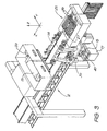
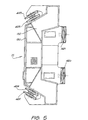
- Figures 3, 4 and 5 show in more detail specific embodiments of a gantry trolley 14 and a head block 15 which can be used in the crane illustrated in Figure 1.
- a first type of hoist cable drive arrangement which includes a total of six hoist drums and their respective drives.
- a total of six reeving cables, designated by numeral 22 are provided to form the reeving 18.
- One end of each of the cables 22 is fixed at the end of the boom in a known manner (not illustrated), whereas the other ends are received on a respective hoist drum 19.
- Three hoist drums 19 are arranged on either side of the gantry 12 in the hoist cable drive arrangement illustrated in Figure 2.
- the hoist drums 19 are driven by conventional motors 20 through a known drive train configuration including gear boxes.
- the hoist drums 19 can either be driven individually or synchronously so as to lengthen or shorten the individual cables 22 conjunctively or differentially.
- a common hoist drum 19 on which all ends of the six cables 22 (not illustrated in Figure 3) are received. The other ends of the cables are fixed as above described at the opposite end of the boom.
- the common hoist drum 19 is arranged overhead and supported on the gantry 12 near the free distal end thereof.
- the hoist drum 19 is driven by a conventional motor 20 through a known reduction gear drive train configuration.
- this hoist drum 19 can only be driven such as to lengthen or shorten the individual cables conjunctively, there is provided a mechanism, generally indicated at 25, arranged to adjust or vary the length of individual reeving cables to provide for full positional and attitudinal control of the head block 15 with respect to the gantry trolley 14 as will be described below.
- the adjustment mechanism 25 for changing the effective length of the cables incorporates six individual rams 26, one from each cable, which may be electrically, hydraulically or pneumatically driven.
- a cable guiding sheave 27 is mounted on the reciprocating drive rod of each ram 32 to loop each cable.
- the cables of the reeving 18 run in sheave and pulley arrangements at the upper trolley 14, generally indicated by numeral 30 in Figure 2 and at the head block generally indicated by numeral 40.
- the sheave and pulley arrangement is indicated by numerals 320-325 and 521-525 and 621-625 in the trolley illustrated in Figures 3, 4, 7 and 8, and by numerals 420-425 in the head block of Figures 3, 5 and 7. This however, will be described in more detail below.
- Figure 6 shows a geometrical representation of the crane as illustrated in Figures 2 and 3.
- the head block 15 is connected geometrically to the support plate or structure of the trolley 14 by way of apexes 24 and 25 of regular, trapezoids 24a and 25a, respectively.
- the shorter sides of the trapezoids 24a and 25a are orientated in opposite directions.
- the lower trapezoid 25a is smaller than the upper trapezoid 24a.
- the sheaves will be mounted on the support structure of the upper trolley 14 and the head block 15, respectively, in such a manner, that the cable runs will coincide as close as physically possible with the apex points of the trapezoids 24a and 25a illustrated in Figure 6.
- a first pair of reeving cables 220 and 221 extend from the corner points 25 of the shorter parallel side of the lower trapezoid 25a in a diverging path towards the corner points 24 of the longer parallel side of the upper trapezoid 24a.
- each cable includes two falls per cable guided around respective sheaves 320 to 325 and 420 to 425 on the upper and lower support structure, respectively, as will be described below.
- a second pair of the reeving cables 222 and 223 extend from the corner points 25 of the longer parallel side of the lower trapezoid 25a in a converging path towards the corner points 24 of the shorter parallel side of the upper trapezoid 24a.
- the third pair of reeving cables 224 and 225 extend between respective opposite lower and upper ends of the first and second pair of reeving cables 220, 221 and 222, 223 at the corner points 24 and 25 of the lower and upper trapezoid 24a and 25a.
- the third pair of reeving cables 224 and 225 extend between the corner points 25 and 24 of the longer parallel sides of the lower and upper trapezoids 25a and 24a, respectively.
- none of the reeving cables 220 to 225 intersect each other between the upper and lower trapezoids 24a and 25a and no two of the reeving cables 220 to 225 extend parallel to one another.
- the effective length of the reeving cables 220 to 225 between the head block 15 and trolley 14 will be identical when the head block 15 and the trolley 14 are in horizontal planes parallel to one another.
- the reeving configuration illustrated enables stable and controllable constraint of the head block 15 with respect to the trolley 14 in x, y and z directions and about the x, y and z axes, that is with respect to rolling, pitching and yawning, respectively.
- the reeving arrangement 18 of Figure 6 as physically embodied in the actual configuration illustrated in Figure 7, is a symmetric reeving which in the present context means that when all the cables are shortened by the same amount, the lower head block 15 and a container 17 attached thereto will rise and fall along the z-axis with respect to the trolley 14 without changing the position of the container 17 along the x-and y-axis nor changing the orientation or attitude of the container 17 about the x-, y- and z-axis (roll, pitch and yawn),
- By shortening or lengthening one or more of the reeving cables 220 to 225 and maintaining or adjusting the tension in the other cables it is possible to induce a controlled and prescribed change in position and/or attitude of the head block 15 with respect to the trolley 14 and maintain such position and attitude while moving the crane 10 as a whole or the trolley 14 along the gantry 12 as has been described above.
- This latter type of adjustment is used for overall positioning while the former can be used
- I 2 226 ( s p + a 3 2 ) 2 + z 2 +( b 2 - x ) 2 +( s p + b 3 2 - y ) 2 +2( s p + a 3 2 ) z sin( ⁇ )cos( ⁇ ) +2( s p + a 3 2 )( b 2 - x )(sin( ⁇ )cos( ⁇ )-sin( ⁇ )sin( ⁇ )cos( ⁇ )) + a ( a +4 z sin( ⁇ )+2cos( ⁇ )cos( ⁇ )( b -2 x )+2sin( ⁇ )cos( ⁇ )( b 3 +2 s p -2 y )) 4 -2( s p + a 3 2 )( s p + b 3 2 - y )(cos( ⁇ )cos( ⁇ )+sin( ⁇ )sin( ⁇ )sin( ⁇ )s
- the Euler angles are not the same as the roll, pitch and yawn angles about the x, y and z axis, but can be easily related to them by known homogenous transformations. It should be further noted that the above geometric equations can be used to determine cable length only when all six cables 220 to 225 are in tension, as otherwise the head block 15 will not be fully constrained relative to the upper trolley 14.
- the position and attitude of the head block 15 with respect to the trolley 14 can be fully controlled in that proper manipulation of the length of the individual reeving cables 220 to 225 between trolley 14 and head block 15 is effected, while the force and moment applied to the head block 15 via the reeving cables 220 to 225 can be fully controlled by corresponding manipulation of the actual tension applied on individual cables.
- the symmetry of the reeving arrangement 18 as illustrated in Figure 6 allows implementation of the single hoisting drum concept illustrated in Figure 3 and described above. All of the free ends of the six reeving cables 220 to 225 are hereby received on the common hoisting drum 19 whereby a common or non-differential hoisting motion along the z-axis is ensured.
- the individual rams 26 with displaceable sheaves 27 arranged within the path of each of the reeving cable 220 to 225 provide the mechanism to shorten or lengthen the actual cable path and therefore vary the length of the individual reeving cables to provide for x- and y- axis-positional and pitch, roll and yawn orientational adjustment of the head block 15.
- the embodiment of the hoist drive of the illustration in Figure 2 uses a combination of two constructional arrangements in that it uses individual hoist drums 19 for individual reeving cables 22, three arranged on each side of the gantry 12, and uses two motors 10, one for each three drum group.
- the actual control mechanism for operating the drives and mechanisms to vary the effective length of individual receiving cables utilising the above given equations such as to obtain the desired movement of the head block 15 with respect to the trolley 14 can be implemented using controller techniques known in the art and will not be described further.
- Locating the connecting points of the reeving cables 220 to 225 on the trolley 14 and the head block 15 to coincide as close as possible with the apexes of regular trapezoids 24a and 25a also increases the stiffness of the hoist as a whole to enable stable transfer of containers 17 having a centre of mass which does not coincide with the geometrical centre of the container.
- the allowable area in which the centre of mass of the container may be contained is increased to be located within the lower trapezoid 25a, thus allowing for greater centre of mass eccentricity while enabling stable, positional control of the head block 15 with respect to the trolley 14.
- the actual spacing distance between the connecting points for the reeving cables at the apexes of the shorter parallel side of the regular trapezoids 24a and 25a on the trolley support plate 14 and head block 15 can be selected based on the maximum allowable dimension of the trolley 14 in direction of the y-axis (see Figures 2 and 3). For example, for a trolley width of 5.0m, if the spacing distance is chosen to be 12.0m, then this will result in an allowable eccentricity of centre of mass of approximately 10% for a 12m container. This value is within the specifications mentioned in the introductory part of the description. This allowable eccentricity increases to 15% for a trolley width of 6m since it is then possible to increase the spacing distance to 2.2m.
- One of the main advantages of the above described reeving arrangement is that it enables to embody a crane with the ability to change the location (both position and orientation in three dimensions) of the head block (and therefore the load) without moving the trolley, that is, it enables fine positional and attitudinal control. This can be achieved by independently operating the hoist motors or ram mechanisms (see above) to vary the reeving cable lengths to change the lengths of the individual cables suspending the head block.
- the feasible rang of x-(along the gantry) and y- (along the quay) motion of the load at a fixed location of the trolley and head block height (along the z-axis) is governed by the geometry of the reeving arrangement.
- the range for y- and x-motion of the head block is 0 to about 1.2m and 0 to about 1m, respectively.
- the range for y- and x-motion of the head block is 0 to about 1.2m and 0 to about 1m, respectively.
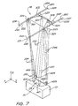
- FIG. 7 A reeving arrangement for the gantry type crane of Figure 1 incorporating the geometric connections illustrated in Figure 6 is illustrated in Figure 7 in a diagrammatic manner.
- the head block and the trolley have been omitted from the illustration for clarity purposes; however, the sheave and pulley arrangement on the head block and trolley support platform are illustrated in part coinciding with the apexes of respective trapezoids so as to facilitate understanding of the actual reeving configuration.
- the same reference numerals as in Figure 6 are used in Figure 7 to refer to physical reeving cable falls between head block and trolley.
- the six reeving cables 220 to 225 are fixed at the boom end of the gantry.
- the other three ends of the reeving cables 220 to 225 are either received on individual hoist or winch drums or a common hoist drum in a manner previously outlined with reference to Figure 2 and 3.
- the cables of the first pair of reeving cables 220 and 221 run along the gantry, one each on opposite sides of the gantry.
- the cables 220 and 221 enter the sheave and pulley arrangement and engage respective guiding sheaves 320 and 321 on the trolley and are directed toward the head block 15 where they engage with respective return sheaves 420 and 421 located at the ends of the smaller parallel side of the trapezoid (see also Figure 5) so as to return to the trolley and be directed by secondary guiding sheaves (not illustrated) respectively associated with the guiding sheaves 320 and 321 to exit the hoist.
- the entry and exit of the respective cables of the first pair 220 and 221 are on the same side of the gantry.
- the reeving cables of the second pair 222 and 223 run along either side of the gantry enter the sheave and pulley arrangement.
- the cables 222 and 223 pass through respective deflection pulleys 522 and 523, via guiding sheaves 322 and 323 (located at the ends of the shorter parallel side of the upper trapezoid) toward return sheaves 422 and 423, respectively, on the head block.
- the sheaves 422 and 423 are arranged at the ends of the longer parallel side of the lower trapezoid (see also Figure 5).
- the cables 222 and 223 return on the same path to engage respective secondary guiding sheaves (not illustrated) associated with the guiding sheaves 322 and 323 from where they pass to be deflected by respective deflection pulleys 522' and 523' to the opposite gantry side.
- entry and exit of the cables 222 and 223 of the second pair is on opposite sides of the gantry.
- the reeving cables 224 and 225 of the third pair run on either side of the gantry and enter the sheave and pulley arrangement to engage respective guiding sheaves 324 and 325 located at the ends of the longer parallel side of the upper trapezoid. From there, cables 224 and 225 run downwardly to the respective return sheaves 424 and 425 arranged at the ends of the longer parallel side of the lower trapezoid (see also Figure 5). Thereafter, cables 224 and 225 return along the same path toward the secondary guiding sheaves associated with the guiding sheaves 324 and 325, respectively, where they are deflected to exit toward the boom.
- entry and exit of the respective cables 224 and 225 is on the same side of the gantry.
- the hoist arrangement (reeving 18 and head block 15) further comprises a sensor system 26 which enables accurate determination of the location of the head block 15, and therefore a container 17 carried by the head block 15, with respect to the trolley 14.
- a set of inertial sensors as indicated at reference numeral 29 in Figure 7 is mounted on the head block 15.
- the sensors include three gyroscopes and a 3-axial accelerometer (or three individual axial accelerometers arranged perpendicular to one another) for measuring the angular velocity and linear accelerations of the head block 15 in three orthogonal directions x, y and z, and two tilt sensors for measuring the orientation of the load with respect to the horizontal x-y plane.
- the data compiled by the sensors can be used to calculate the position and attitude of the head block 15 with respect to the trolley 14. This data can be incorporated into the control algorithms used to drive the trolley 14 and hoist drives so as to minimise load sway and accurately position a container carried by the hoisting arrangement. This data can also be used to assist the crane operator to manoeuvre the head block in a controlled and stable manner to engage a container to be loaded or unloaded.
- the actual gantry trolley 14 illustrated in Figure 4 has a mirror symmetrical design about the longitudinal axis extending in x-direction, and therefore the run of reeving cables on the sheave and pulley arrangement illustrated on the left hand side will be mirror symmetrical to the one illustrated on the right hand side.
- the gantry trolley 14 incorporates two main support beams or boxes 142 which are arranged parallel to one another and respectively support at opposite distal ends one carriage 144 by means of which the trolley is supported on guiding beams of the gantry 12 such as to allow translatory movement in direction of axis x along the gantry extension.
- a total of four downward extending support arms 146 join two support platform halves 140 to respective one of the support beams 142.
- Two bracing beams 148 disposed on the underside of the support forms 140 braise and interconnect the trolley structure to provide the required structural rigidity.
- the arrangement of guiding sheaves and deflection and guide pulleys is generally indicated at 30.
- Some of the pulley/sheave disks are supported for rotation about horizontally extending axes and some about vertical axes on respective mounting arms, two exemplarily being indicated at 31, which are fixedly mounted on the support platforms 140 in an arrangement dictated by the above mentioned geometrical reeving configuration and the necessity to avoid collision of cable runs.
- the head block 15 illustrated in Figure 5 can be a rather simple support structure comprised of a number of struts and beams 150 which support plate members 152 which themselves support bearings for the return sheaves 420-425 provided in the trapezoid arrangement previously described.
- all guide pulleys arranged on the lower part of the support platform 140 are preceded by the number 6; deflection pulleys arranged on the upper part of the support platform are preceded by the number 5; and the guiding sheaves which serve to direct the reeving cables in a downward direction and receive the returning cable run from the not illustrated block head are preceded by the number 3.
- the last two numerals used to distinguish the individual sheaves and pulleys corresponds to the last two digits of the reference numeral used to identify an individual reeving cables 221, 223 and 225.
- reeving cable 221, 223 and 225 enter the sheave and pulley arrangement from the lower right hand side of the drawing plane and leave the arrangement towards the upper left hand corner.
- reeving cable 221 enters from the lower side of the trolley and engages guide pulley 621 from where it passes towards the upper part of support plate to directly be received by guiding sheave 321 and be directed downwards towards the head block. Due to the perspective illustration of Figure 8, it is not clearly apparent but it is to be understood that guiding sheave 321 is arranged near an apex of the longer parallel side of the upper trapezoid in similar manner as illustrated in Figure 7.
- Reeving cable 221 is received on return sheave 421 of the head block illustrated in Figure 5 and returned in an upward direction to be received at guiding sheave 321', which in the above given description with reference to Figure 7 is called a secondary guiding sheave.
- Reeving cable 221 then passes through guiding pulley 521 where it is deflected in a downward direction to a not illustrated further guiding pulley arranged on the lower side of the trolley to exit the arrangement in the manner outlined above.
- Reeving cable 223 enters the arrangement to be deflected at lower guiding pulley 623 to be directed in an upward direction to guiding sheave 323 from where the reeving cable 223 runs downward towards the head block.
- Cable 223 is returned at guide sheave 423 to run in an upward direction and then to be received at guiding sheave 323' from where it is directed again downwards to lower a guiding pulley 623' and subsequently redirected to exit the pulley arrangement towards the left hand corner of the illustration.
- Guiding sheaves 323 are located near the apex of the shorter side of the upper trapezium.
- reeving cable 225 enters the pulley arrangement to engage lower guiding pulley 625 to be passed to the upper side of the trolley and engage guiding pulley 525.
- Reeving cable 225 then passes to a guiding pulley 525' having a rotation axis substantially extending in a vertical direction.
- Reeving cable 225 is subsequently deflected toward guiding sheave 325 to be directed in a downward direction towards the return sheave 425 at the head block from where it returns in an upward direction to engage guiding sheave 325'.
- reeving cable 225 is deflected by means of a horizontally rotating guiding pulley 525" towards deflection pulley 525''' which directs the cable in an not illustrated manner towards the lower part of the trolley where it engages a not illustrated lower guiding pulley to exit the sheave arrangement.
- the above described reeving configuration for a crane embodiment allows stable and controlled manipulation of the head block 15 with respect to the trolley 14.
- fine positioning of the head block 15 can be achieved to pick-up a container once gross-positional adjustment of the trolley 14 and herefrom suspended head block 15 has been accomplished.
- the proposed reeving arrangement 18 also provides potential for active anti-sway and damping control since the reeving arrangement 18 can be manipulated to respond in a stable, predetermined, manner to counter any forces which will induce load sway.
Landscapes
- Engineering & Computer Science (AREA)
- Mechanical Engineering (AREA)
- Control And Safety Of Cranes (AREA)
- Carriers, Traveling Bodies, And Overhead Traveling Cranes (AREA)
- Combined Means For Separation Of Solids (AREA)
Claims (16)
- Kran (10), der aufweist: eine obere Tragkonstruktion (14); eine untere Tragkonstruktion (15), die so angeordnet ist, daß sie eine Last (17) trägt; sechs Flaschenzugseile (18), die die untere Tragkonstruktion von der oberen Tragkonstruktion aus hängend angeordnen; und eine Einrichtung (19, 20) für das Verändern der wirksamen Länge zwischen der oberen und unteren Tragkonstruktion von ausgewählten Seilen der Flaschenzugseile, dadurch gekennzeichnet, daß die Flaschenzugseile geometrisch mit der oberen und der unteren Tragkonstruktion in Scheitelpunkten (24, 25) des entsprechenden Trapezes (24a, 25a) verbunden sind, wobei die Flaschenzugseile so angeordnet sind, daß die Seile (220, 221) eines ersten Paares von Flaschenzugseilen in einer Richtung nach unten konvergieren, die Seile (222, 223) eines zweiten Paares von Flaschenzugseilen in einer Richtung nach oben konvergieren, und sich die Seile (224, 225) des dritten Paares von Flaschenzugseilen zwischen gegenüberliegenden Enden des ersten und zweiten Paares der Flaschenzugseile an der oberen und unteren Konstruktion erstrecken.
- Kran nach Anspruch 1, bei dem die Flaschenzugseile (18) geometrisch an Punkten in der oberen und unteren Tragkonstruktion (14, 15) verbunden sind, die mit den Scheitelpunkten (24, 25) der Trapeze (24a, 25a) zusammenfallen.
- Kran nach Anspruch 1 oder 2, bei dem die Flaschenzugseile (18) geometrisch an Punkten in der oberen und unteren Tragkonstruktion (14, 15) verbunden sind, die mit den Scheitelpunkten (24, 25) der regelmäßigen Trapeze (24a, 25a) zusammenfallen.
- Kran nach einem der vorhergehenden Ansprüche, bei dem die Fläche des Trapezes (24a), die durch die geometrischen Verbindungspunkte (24) in der oberen Tragkonstruktion (14) definiert wird, größer ist als die Fläche des Trapezes (25a), die durch die geometrischen Verbindungspunkte (25) in der unteren Tragkonstruktion (15) definiert wird.
- Kran nach einem der vorhergehenden Ansprüche, bei dem die Flaschenzugseile (18) geometrisch an Punkten (24, 25) in der oberen und unteren Tragkonstruktion (14, 15) verbunden werden, die im wesentlichen mit den Scheitelpunkten der regelmäßigen Trapeze zusammenfallen, wobei die Abstände (25) zwischen den Scheitelpunkten an den kürzeren parallelen Seiten des oberen und unteren Trapezes (24a, 25a) gleich sind, wobei der Abstand zwischen den Scheitelpunkten an der längeren parallelen Seite des unteren Trapezes gleich dem Abstand zwischen den Scheitelpunkten an den kürzeren parallelen Seiten plus √3R ist, worin R der Radius eines Kreises ist, der ein gleichseitiges Dreieck mit einer Seitenlänge gleich dem Abstand zwischen den Scheitelpunkten der nicht parallelen Seiten des unteren Trapezes umschreibt, und der Abstand zwischen den Scheitelpunkten an der parallelen Seite des oberen Trapezes gleich dem Abstand zwischen den Scheitelpunkten an den kürzeren parallelen Seiten plus 2√3R ist.
- Kran nach einem der vorhergehenden Ansprüche und angeordnet als ein Portalkran (12, 10) für das Anheben von Containern (17), bei dem die obere Tragkonstruktion eine Laufkatze (14) aufweist, die für eine hin- und hergehende lineare Bewegung längs einer Portal- oder Auslegerkonstruktion (12) des Kranes angeordnet ist, und bei dem die untere Tragkonstruktion einen Kopfblock (15) aufweist, an dem der Container mittels eines Anschlagrahmens (16) gekoppelt werden kann.
- Kran nach einem der vorhergehenden Ansprüche, bei dem die Einrichtung für das Verändern der wirksamen Länge eines jeden der Flaschenzugseile (18) zwischen der oberen und der unteren Tragkonstruktion (14, 15) eine Vielzahl von Seiltrommeln (19) aufweist, eine für jedes der Flaschenzugseile.
- Kran nach Anspruch 7, bei dem die Seiltrommeln durch einzelne Motoren (20) oder durch einen gemeinsamen Motor angetrieben werden, um eine feine Stellungskontrolle der unteren Tragkonstruktion (15) mit Bezugnahme auf die obere Tragkonstruktion (14) zu bewirken, wobei ein Übertragungssystem bereitgestellt wird, um eine differentielle Bewegung der einzelnen Seiltrommeln zu bewirken.
- Kran nach einem der Ansprüche 1 bis 7, bei dem die Einrichtung für das Verändern der wirksamen Länge eines jeden (22) der Flaschenzugseile zwischen der oberen und der unteren Tragkonstruktion eine einzelne motorgetriebene Seiltrommel (19, 20) für alle Flaschenzugseile aufweist und eine Einstelleinrichtung (25) innerhalb des Weges eines jeden Flaschenzugseiles angeordnet ist, um eine zusätzliche einzelne Regulierung der Längen eines jeden der Flaschenzugseile zu bewirken.
- Kran nach Anspruch 9, bei dem die Einstelleinrichtung (25) elektrisch, hydraulisch oder pneumatisch aktivierte Kolben (26) mit einem Seilführungselement (27) umfaßt.
- Kran nach einem der Ansprüche 8, 9 oder 10, der außerdem einen elektronischen Regler aufweist, der angeordnet ist, um Steuerbefehle zu liefern, die bei der Einrichtung für das Verändern der wirksamen Länge der Flaschenzugseile (18) in Übereinstimmung mit geometrischen Gleichungen wirksam sind, die die räumliche Stellung oder dreidimensionale Ausrichtung der unteren Tragkonstruktion (15) mit den wirksamen Abständen zwischen den Scheitelpunkten der Trapeze (25a, 24a) in der unteren und der oberen Tragkonstruktion verbinden, wie beispielsweise, um eine vorgegebene Länge und Zugspannung in jedem (22) der Flaschenzugseile zu regulieren und aufrechtzuerhalten, die mit der räumlichen Stellung in Verbindung stehen.
- Kran nach Anspruch 11, der außerdem eine Sensoreinrichtung (29) für das Ermitteln der räumlichen Position und der dreidimensionalen Ausrichtung der unteren Tragkonstruktion (15) mit Bezugnahme auf die obere Tragkonstruktion (14) aufweist.
- Kran nach Anspruch 12, der außerdem eine Rückkopplungseinrichtung umfaßt, die angeordnet ist, um dem elektronischen Regler die Position und die Ausrichtung innerhalb der unteren Tragkonstruktion (15) mit Bezugnahme auf die obere Tragkonstruktion (14) zu übermitteln, wie sie mittels der Sensoreinrichtung (29) ermittelt werden, wobei der elektronische Regler angeordnet ist, um die Position und Ausrichtung der unteren Tragkonstruktion als Reaktion auf die von der Rückkopplungseinrichtung gelieferten Rückkopplungsdaten fein zu regulieren.
- Kran nach Anspruch 13, bei dem der elektronische Regler angeordnet ist, um automatisch auf die Rückkopplungseinrichtung derart anzusprechen, daß die Einrichtung (25) für das Verändern der wirksamen Länge der Flaschenzugseile (18) betätigt wird, um automatisch extern angelegten Kräften entgegenzuwirken, denen die von der unteren Tragkonstruktion (15) beförderte Last ausgesetzt werden kann.
- Kran nach Anspruch 12, 13 oder 14, bei dem die Sensoreinrichtung (19) eine Trägheitsladebühne umfaßt, die aus Gyroskopen und Beschleunigungsmessern besteht, die an der unteren Tragkonstruktion angeordnet sind.
- Kran nach Anspruch 14 oder 15, bei dem der elektronische Regler außerdem angeordnet ist, um die Länge der Flaschenzugseile (18) mittels der Einrichtung (25) für das Verändern der wirksamen Länge der Flaschenzugseile automatisch zu regulieren, wenn Rückkopplungsdaten empfangen werden, die auf eine abnormale Position oder Ausrichtung der Last (17) hinweisen.
Applications Claiming Priority (4)
| Application Number | Priority Date | Filing Date | Title |
|---|---|---|---|
| AUPN681195 | 1995-11-24 | ||
| AUPN6811/95 | 1995-11-24 | ||
| AUPN6811A AUPN681195A0 (en) | 1995-11-24 | 1995-11-24 | Container handling crane |
| PCT/AU1996/000749 WO1997019888A1 (en) | 1995-11-24 | 1996-11-22 | Crane with improved reeving arrangement |
Publications (3)
| Publication Number | Publication Date |
|---|---|
| EP0865406A1 EP0865406A1 (de) | 1998-09-23 |
| EP0865406A4 EP0865406A4 (de) | 1999-12-15 |
| EP0865406B1 true EP0865406B1 (de) | 2003-07-02 |
Family
ID=3791133
Family Applications (1)
| Application Number | Title | Priority Date | Filing Date |
|---|---|---|---|
| EP96938848A Expired - Lifetime EP0865406B1 (de) | 1995-11-24 | 1996-11-22 | Kran mit verbesserter flaschenzuganordnung |
Country Status (7)
| Country | Link |
|---|---|
| US (1) | US6126023A (de) |
| EP (1) | EP0865406B1 (de) |
| JP (1) | JP3938597B2 (de) |
| KR (1) | KR100407186B1 (de) |
| AU (2) | AUPN681195A0 (de) |
| DE (1) | DE69628939T2 (de) |
| WO (1) | WO1997019888A1 (de) |
Families Citing this family (38)
| Publication number | Priority date | Publication date | Assignee | Title |
|---|---|---|---|---|
| FR2769906B1 (fr) * | 1997-10-22 | 2000-04-07 | Sncf | Dispositif anti-ballant pour appareil de levage a cables croises |
| ATE282190T1 (de) * | 1999-04-01 | 2004-11-15 | Deutsch Zentr Luft & Raumfahrt | Messanordnung zur regelung von ausladenden mechanischen vorrichtungen wie robotern oder werkzeugmaschinen sowie messverfahren dazu |
| DE19918449C2 (de) * | 1999-04-23 | 2001-09-13 | Noell Stahl Und Maschb Gmbh | Lasthebesystem zur Feinpositionierung und aktiven Schwingungsdämpfung |
| US6566834B1 (en) * | 1999-09-28 | 2003-05-20 | The United States Of America As Represented By The Secretary Of Commerce | Modular suspended manipulator |
| US7121012B2 (en) * | 1999-12-14 | 2006-10-17 | Voecks Larry A | Apparatus and method for measuring and controlling pendulum motion |
| US7845087B2 (en) * | 1999-12-14 | 2010-12-07 | Voecks Larry A | Apparatus and method for measuring and controlling pendulum motion |
| DE10029579B4 (de) * | 2000-06-15 | 2011-03-24 | Hofer, Eberhard P., Prof. Dr. | Verfahren zur Orientierung der Last in Krananlagen |
| US7627393B2 (en) * | 2000-10-19 | 2009-12-01 | Liebherr-Werk Nenzing Gmbh | Crane or digger for swinging a load hanging on a support cable with damping of load oscillations |
| US6826452B1 (en) * | 2002-03-29 | 2004-11-30 | The Penn State Research Foundation | Cable array robot for material handling |
| DE10218260B4 (de) * | 2002-04-24 | 2005-09-22 | MAN TAKRAF Fördertechnik GmbH | Hubseilführung für einen Containerkran |
| DE10245868B4 (de) * | 2002-09-30 | 2019-10-10 | Siemens Aktiengesellschaft | Verfahren und Vorrichtung zur Positionierung einer Last |
| KR20050020260A (ko) * | 2003-08-21 | 2005-03-04 | 현대중공업 주식회사 | 대각선의 장력조절 장치를 이용한 화물의 인양공법 |
| US7289875B2 (en) * | 2003-11-14 | 2007-10-30 | Siemens Technology-To-Business Center Llc | Systems and methods for sway control |
| DE202005002315U1 (de) * | 2005-02-11 | 2005-06-16 | Isam Ag | Vorrichtung zum Be- und/oder Entladen eines Laderaums mit Schüttgut, insbesondere zum Be- und/oder Entladen eines Laderaumes eines Schiffes mit Kohle, Erz o.dgl. |
| CN101128383B (zh) * | 2005-02-25 | 2010-10-13 | 奥蒂斯电梯公司 | 具有成角度设置的下悬式挂绳布置的电梯轿厢 |
| DE102007012575A1 (de) | 2007-03-13 | 2008-09-18 | Putzmeister Concrete Pumps Gmbh | Großmanipulator |
| DE102007041692A1 (de) * | 2007-09-03 | 2009-03-05 | Siemens Ag | Regelungseinrichtung zur Dämpfung von Pendelbewegungen einer seilgeführten Last |
| US20090125196A1 (en) * | 2007-11-14 | 2009-05-14 | Honeywell International, Inc. | Apparatus and method for monitoring the stability of a construction machine |
| JP5738977B2 (ja) * | 2010-04-01 | 2015-06-24 | パー システムズ, インコーポレイテッド | 張力トラスマスト |
| US9096294B1 (en) * | 2011-06-20 | 2015-08-04 | The United States Of America As Represented By The Secretary Of The Navy | Trolley-payload inter-ship transfer system |
| CN102431897B (zh) * | 2011-11-25 | 2014-04-30 | 林汉丁 | 起重机吊装垂直度偏差测量显示装置及吊装法 |
| US9016464B2 (en) | 2012-04-04 | 2015-04-28 | Sst Systems, Inc. | Tilting multiplier |
| US9950910B2 (en) * | 2012-09-11 | 2018-04-24 | Eltronic A/S | Method for controlling the orientation of a load suspended from a bearing wire about said bearing wire and a winch arrangement |
| US9834418B2 (en) | 2012-09-21 | 2017-12-05 | Par Systems, Inc. | Boat deployment assembly and method |
| US10494233B2 (en) | 2013-02-06 | 2019-12-03 | Par Systems, Llc | Relocatable fine motion positioner assembly on an overhead crane |
| US9468944B2 (en) | 2013-05-17 | 2016-10-18 | Sst Systems, Inc. | System and method with multi-axis tilting |
| WO2016019289A1 (en) * | 2014-07-31 | 2016-02-04 | Par Systems, Inc. | Crane motion control |
| US10137819B2 (en) * | 2015-02-16 | 2018-11-27 | Wastequip, Llc | Hoist assembly |
| PL3165493T3 (pl) | 2015-11-06 | 2019-12-31 | Fundación Tecnalia Research & Innovation | Urządzenie i sposób pozycjonowania i orientowania ładunku |
| US9945114B2 (en) * | 2016-06-28 | 2018-04-17 | The United States Of America As Represented By Secretary Of The Navy | System and method for the rapid installation of a portable building in a confined vertically inaccessible location |
| KR102144243B1 (ko) | 2017-02-08 | 2020-08-12 | 유니버셜 시티 스튜디오스 엘엘씨 | 움직임 생성 플랫폼 조립체 |
| WO2018179369A1 (ja) * | 2017-03-31 | 2018-10-04 | 平田機工株式会社 | 搬送装置 |
| ES2809152T3 (es) * | 2017-09-28 | 2021-03-03 | Mohr Lizenz Verwaltungs Gmbh | Dispositivo elevador para subir y bajar objetos pesados |
| US10457493B1 (en) | 2018-08-08 | 2019-10-29 | Sst Systems, Inc. | Indexing conveyor system and method |
| DE102018123301B4 (de) * | 2018-09-21 | 2021-04-15 | Liebherr-Werk Ehingen Gmbh | Verfahren zur Ermittlung der Seileinscherung eines Flaschenzuges |
| KR102080617B1 (ko) * | 2018-11-29 | 2020-02-24 | 홍득표 | 러핑형 타워크레인의 지브 엔드 하부롤러 조립체 |
| US20240182272A1 (en) * | 2022-12-06 | 2024-06-06 | Shawn Albert Carter | Hoisting apparatus with automated load leveling |
| CN116621032B (zh) * | 2023-05-25 | 2024-04-09 | 广州港股份有限公司 | 适用于集装箱吊具精准定位特性且提高调整效率的方法 |
Family Cites Families (19)
| Publication number | Priority date | Publication date | Assignee | Title |
|---|---|---|---|---|
| US2916162A (en) * | 1953-11-06 | 1959-12-08 | Maschf Augsburg Nuernberg Ag | Apparatus for damping pendulum motions of the load suspended from a lifting machine |
| US3081884A (en) * | 1961-06-09 | 1963-03-19 | Manning Maxwell & Moore Inc | Crane with anti-sway mechanism |
| US3309966A (en) * | 1964-06-11 | 1967-03-21 | Gen Motors Corp | Differential pressure hydraulic valve and fluid motor |
| US3276602A (en) * | 1964-08-06 | 1966-10-04 | Arthur W Vogeley | Cable arrangement for rigid tethering |
| US3308966A (en) * | 1965-09-03 | 1967-03-14 | Joseph E Fawell | Travelling stabilized crane |
| US3476263A (en) * | 1966-08-02 | 1969-11-04 | Ishikawajima Harima Heavy Ind | Device for preventing the swaying of the suspending means in a crane |
| GB1162878A (en) * | 1967-06-09 | 1969-08-27 | John Stevenson Thomson | Improvements relating to Cranes for Handling Containers |
| US3532324A (en) * | 1968-05-23 | 1970-10-06 | Paceco Inc | Antisway mechanism |
| DE2014656B2 (de) * | 1970-03-26 | 1974-04-25 | Institutul De Cercetare Si Proiectare Pentru Masini De Transportat Si Ridicat Timisoara, Timisoara (Rumaenien) | Vorrichtung zur pendelfreien Lastaufhängung von Magnettraversen an Kranhaken von Laufkatzen |
| US3945503A (en) * | 1970-10-02 | 1976-03-23 | Fruehauf Corporation | Crane with a variable center rope suspension system |
| NL7101224A (de) * | 1971-01-29 | 1972-08-01 | ||
| AU471953B2 (en) * | 1972-12-29 | 1976-05-06 | Ishikawajima-Harima Jukogyo K.K. | Device for preventing the swaying ofthe suspending means ina crane |
| FR2443996A1 (fr) * | 1978-12-15 | 1980-07-11 | Potain Sa | Engin de levage tel que grue ou portique pour la manutention de conteneurs |
| GB8415934D0 (en) * | 1984-06-22 | 1984-07-25 | Handling Consultants Ltd | Equipment for handling loads |
| EP0246922A3 (de) * | 1986-05-23 | 1990-02-07 | James S. Albus | Kabelanordnung und Hebeplattform zum Stabilisieren einer Last beim Heben |
| DE3737082A1 (de) * | 1987-10-31 | 1989-05-18 | Orenstein & Koppel Ag | Aufhaengevorrichtung fuer hubtraversen fuer container |
| US4905848A (en) * | 1988-06-06 | 1990-03-06 | Skjonberg Knut B | Coordinated hoist controllers |
| FR2643353B1 (fr) * | 1989-02-17 | 1991-06-14 | Caillard | Dispositif pour eviter le balancement d'une charge sous un bati de support, notamment un portique |
| US5257891A (en) * | 1991-02-19 | 1993-11-02 | Mi-Jack Products, Inc. | Bi-planar cable cross reeving system |
-
1995
- 1995-11-24 AU AUPN6811A patent/AUPN681195A0/en not_active Abandoned
-
1996
- 1996-11-22 DE DE69628939T patent/DE69628939T2/de not_active Expired - Fee Related
- 1996-11-22 EP EP96938848A patent/EP0865406B1/de not_active Expired - Lifetime
- 1996-11-22 JP JP51999997A patent/JP3938597B2/ja not_active Expired - Fee Related
- 1996-11-22 AU AU76126/96A patent/AU701612B2/en not_active Ceased
- 1996-11-22 WO PCT/AU1996/000749 patent/WO1997019888A1/en not_active Ceased
- 1996-11-22 KR KR10-1998-0703885A patent/KR100407186B1/ko not_active Expired - Fee Related
- 1996-11-22 US US09/077,216 patent/US6126023A/en not_active Expired - Fee Related
Also Published As
| Publication number | Publication date |
|---|---|
| WO1997019888A1 (en) | 1997-06-05 |
| EP0865406A4 (de) | 1999-12-15 |
| AUPN681195A0 (en) | 1995-12-21 |
| AU7612696A (en) | 1997-06-19 |
| EP0865406A1 (de) | 1998-09-23 |
| KR100407186B1 (ko) | 2004-04-08 |
| DE69628939T2 (de) | 2004-06-17 |
| US6126023A (en) | 2000-10-03 |
| AU701612B2 (en) | 1999-02-04 |
| JP2000500424A (ja) | 2000-01-18 |
| DE69628939D1 (de) | 2003-08-07 |
| JP3938597B2 (ja) | 2007-06-27 |
| KR19990071609A (ko) | 1999-09-27 |
Similar Documents
| Publication | Publication Date | Title |
|---|---|---|
| US6126023A (en) | Crane with improved reeving arrangement | |
| EP3165493B1 (de) | Vorrichtung und verfahren zur positionierung und ausrichtung einer last | |
| Parker et al. | Experimental verification of a command shaping boom crane control system | |
| US4932541A (en) | Stabilized shipboard crane | |
| US7367464B1 (en) | Pendulation control system with active rider block tagline system for shipboard cranes | |
| EP3212559B1 (de) | Trägersystem für hängende last | |
| US6496765B1 (en) | Control system and method for payload control in mobile platform cranes | |
| US4883184A (en) | Cable arrangement and lifting platform for stabilized load lifting | |
| US20080093322A1 (en) | Parallel Kinematic Mechanism | |
| NL2023415B1 (en) | hoisting arrangement for assembly of wind turbines | |
| JPH07508488A (ja) | 荷重用の持上げ装置 | |
| Petković et al. | Automation of ship-to-shore container cranes: A review of state-of-the-art | |
| EP0246922A2 (de) | Kabelanordnung und Hebeplattform zum Stabilisieren einer Last beim Heben | |
| JP2022094983A (ja) | タワークレーンの吊荷の振れ止め装置、位置決め装置、振れ止め方法、及び、位置決め方法 | |
| CN115196521B (zh) | 一种利用船舶稳性调节船用起重设备的控制系统 | |
| EP1611046B1 (de) | Verfahren zur steuerung des hebegeschirrs in einem kran | |
| CN112456352B (zh) | 一种多自由度主动式波浪补偿装置 | |
| CN105438981A (zh) | 船用可折叠防摆装置 | |
| CN118585005A (zh) | 具有吊装补偿登陆三位一体的海上廊桥控制系统及方法 | |
| US20220177279A1 (en) | Knuckle boom crane, for offshore application | |
| CN223328923U (zh) | 一种船舶吊装平台 | |
| JP3251720B2 (ja) | 吊り荷の揺れ止め装置 | |
| EP0952955A1 (de) | Kran | |
| HK1236177B (en) | Suspended load carrying system | |
| HK1236177A1 (en) | Suspended load carrying system |
Legal Events
| Date | Code | Title | Description |
|---|---|---|---|
| PUAI | Public reference made under article 153(3) epc to a published international application that has entered the european phase |
Free format text: ORIGINAL CODE: 0009012 |
|
| 17P | Request for examination filed |
Effective date: 19980527 |
|
| AK | Designated contracting states |
Kind code of ref document: A1 Designated state(s): BE DE DK ES FI FR GB GR IE IT NL PT SE |
|
| A4 | Supplementary search report drawn up and despatched |
Effective date: 19991102 |
|
| AK | Designated contracting states |
Kind code of ref document: A4 Designated state(s): BE DE DK ES FI FR GB GR IE IT NL PT SE |
|
| 17Q | First examination report despatched |
Effective date: 20011019 |
|
| GRAH | Despatch of communication of intention to grant a patent |
Free format text: ORIGINAL CODE: EPIDOS IGRA |
|
| GRAH | Despatch of communication of intention to grant a patent |
Free format text: ORIGINAL CODE: EPIDOS IGRA |
|
| GRAA | (expected) grant |
Free format text: ORIGINAL CODE: 0009210 |
|
| AK | Designated contracting states |
Designated state(s): BE DE DK ES FI FR GB GR IE IT NL PT SE |
|
| PG25 | Lapsed in a contracting state [announced via postgrant information from national office to epo] |
Ref country code: FI Free format text: LAPSE BECAUSE OF FAILURE TO SUBMIT A TRANSLATION OF THE DESCRIPTION OR TO PAY THE FEE WITHIN THE PRESCRIBED TIME-LIMIT Effective date: 20030702 Ref country code: BE Free format text: LAPSE BECAUSE OF FAILURE TO SUBMIT A TRANSLATION OF THE DESCRIPTION OR TO PAY THE FEE WITHIN THE PRESCRIBED TIME-LIMIT Effective date: 20030702 |
|
| REG | Reference to a national code |
Ref country code: GB Ref legal event code: FG4D |
|
| REG | Reference to a national code |
Ref country code: IE Ref legal event code: FG4D |
|
| REF | Corresponds to: |
Ref document number: 69628939 Country of ref document: DE Date of ref document: 20030807 Kind code of ref document: P |
|
| PG25 | Lapsed in a contracting state [announced via postgrant information from national office to epo] |
Ref country code: SE Free format text: LAPSE BECAUSE OF FAILURE TO SUBMIT A TRANSLATION OF THE DESCRIPTION OR TO PAY THE FEE WITHIN THE PRESCRIBED TIME-LIMIT Effective date: 20031002 Ref country code: PT Free format text: LAPSE BECAUSE OF FAILURE TO SUBMIT A TRANSLATION OF THE DESCRIPTION OR TO PAY THE FEE WITHIN THE PRESCRIBED TIME-LIMIT Effective date: 20031002 Ref country code: GR Free format text: LAPSE BECAUSE OF FAILURE TO SUBMIT A TRANSLATION OF THE DESCRIPTION OR TO PAY THE FEE WITHIN THE PRESCRIBED TIME-LIMIT Effective date: 20031002 Ref country code: DK Free format text: LAPSE BECAUSE OF FAILURE TO SUBMIT A TRANSLATION OF THE DESCRIPTION OR TO PAY THE FEE WITHIN THE PRESCRIBED TIME-LIMIT Effective date: 20031002 |
|
| PG25 | Lapsed in a contracting state [announced via postgrant information from national office to epo] |
Ref country code: ES Free format text: LAPSE BECAUSE OF FAILURE TO SUBMIT A TRANSLATION OF THE DESCRIPTION OR TO PAY THE FEE WITHIN THE PRESCRIBED TIME-LIMIT Effective date: 20031013 |
|
| PG25 | Lapsed in a contracting state [announced via postgrant information from national office to epo] |
Ref country code: IE Free format text: LAPSE BECAUSE OF NON-PAYMENT OF DUE FEES Effective date: 20031124 |
|
| ET | Fr: translation filed | ||
| PLBE | No opposition filed within time limit |
Free format text: ORIGINAL CODE: 0009261 |
|
| STAA | Information on the status of an ep patent application or granted ep patent |
Free format text: STATUS: NO OPPOSITION FILED WITHIN TIME LIMIT |
|
| 26N | No opposition filed |
Effective date: 20040405 |
|
| REG | Reference to a national code |
Ref country code: IE Ref legal event code: MM4A |
|
| PGFP | Annual fee paid to national office [announced via postgrant information from national office to epo] |
Ref country code: NL Payment date: 20061105 Year of fee payment: 11 |
|
| PGFP | Annual fee paid to national office [announced via postgrant information from national office to epo] |
Ref country code: FR Payment date: 20061108 Year of fee payment: 11 |
|
| PGFP | Annual fee paid to national office [announced via postgrant information from national office to epo] |
Ref country code: DE Payment date: 20061116 Year of fee payment: 11 |
|
| PGFP | Annual fee paid to national office [announced via postgrant information from national office to epo] |
Ref country code: GB Payment date: 20061122 Year of fee payment: 11 |
|
| PGFP | Annual fee paid to national office [announced via postgrant information from national office to epo] |
Ref country code: IT Payment date: 20061130 Year of fee payment: 11 |
|
| GBPC | Gb: european patent ceased through non-payment of renewal fee |
Effective date: 20071122 |
|
| NLV4 | Nl: lapsed or anulled due to non-payment of the annual fee |
Effective date: 20080601 |
|
| PG25 | Lapsed in a contracting state [announced via postgrant information from national office to epo] |
Ref country code: NL Free format text: LAPSE BECAUSE OF NON-PAYMENT OF DUE FEES Effective date: 20080601 Ref country code: DE Free format text: LAPSE BECAUSE OF NON-PAYMENT OF DUE FEES Effective date: 20080603 |
|
| REG | Reference to a national code |
Ref country code: FR Ref legal event code: ST Effective date: 20080930 |
|
| PG25 | Lapsed in a contracting state [announced via postgrant information from national office to epo] |
Ref country code: GB Free format text: LAPSE BECAUSE OF NON-PAYMENT OF DUE FEES Effective date: 20071122 |
|
| PG25 | Lapsed in a contracting state [announced via postgrant information from national office to epo] |
Ref country code: FR Free format text: LAPSE BECAUSE OF NON-PAYMENT OF DUE FEES Effective date: 20071130 |
|
| PG25 | Lapsed in a contracting state [announced via postgrant information from national office to epo] |
Ref country code: IT Free format text: LAPSE BECAUSE OF NON-PAYMENT OF DUE FEES Effective date: 20071122 |