EP0865528B1 - Schwenkbare trageeinrichtung und entfaltbare panele - Google Patents
Schwenkbare trageeinrichtung und entfaltbare panele Download PDFInfo
- Publication number
- EP0865528B1 EP0865528B1 EP96922691A EP96922691A EP0865528B1 EP 0865528 B1 EP0865528 B1 EP 0865528B1 EP 96922691 A EP96922691 A EP 96922691A EP 96922691 A EP96922691 A EP 96922691A EP 0865528 B1 EP0865528 B1 EP 0865528B1
- Authority
- EP
- European Patent Office
- Prior art keywords
- link
- links
- working position
- planar element
- ironing
- Prior art date
- Legal status (The legal status is an assumption and is not a legal conclusion. Google has not performed a legal analysis and makes no representation as to the accuracy of the status listed.)
- Expired - Lifetime
Links
- 238000010409 ironing Methods 0.000 claims description 63
- 230000000712 assembly Effects 0.000 claims description 12
- 238000000429 assembly Methods 0.000 claims description 12
- 230000000295 complement effect Effects 0.000 claims description 2
- 230000007246 mechanism Effects 0.000 description 11
- 230000009286 beneficial effect Effects 0.000 description 1
- 230000000694 effects Effects 0.000 description 1
- 239000002184 metal Substances 0.000 description 1
- 238000000034 method Methods 0.000 description 1
- 230000000452 restraining effect Effects 0.000 description 1
Images



Classifications
-
- A—HUMAN NECESSITIES
- A47—FURNITURE; DOMESTIC ARTICLES OR APPLIANCES; COFFEE MILLS; SPICE MILLS; SUCTION CLEANERS IN GENERAL
- A47B—TABLES; DESKS; OFFICE FURNITURE; CABINETS; DRAWERS; GENERAL DETAILS OF FURNITURE
- A47B5/00—Suspended or hinged panels forming a table; Wall tables
- A47B5/06—Suspended or hinged panels forming a table; Wall tables with legs for supporting the table on the floor
-
- A—HUMAN NECESSITIES
- A47—FURNITURE; DOMESTIC ARTICLES OR APPLIANCES; COFFEE MILLS; SPICE MILLS; SUCTION CLEANERS IN GENERAL
- A47B—TABLES; DESKS; OFFICE FURNITURE; CABINETS; DRAWERS; GENERAL DETAILS OF FURNITURE
- A47B77/00—Kitchen cabinets
- A47B77/04—Provision for particular uses of compartments or other parts ; Compartments moving up and down, revolving parts
- A47B77/10—Provision for particular uses of compartments or other parts ; Compartments moving up and down, revolving parts with members movable outwards to a position of use, e.g. tables, ironing boards
Definitions
- THIS INVENTION relates to a hinge mechanism applicable to angularly movable wings such as a foldaway ironing board assembly and to assemblies employing the hinge mechanism such as a foldaway ironing board assembly mounted to a support structure such as a wall, kitchen unit, cupboard bench support, mobile cabinet or drawer.
- foldaway ironing board assemblies which save space and offer advantages over more conventional portable ironing boards which are supported from the ground by scissor action legs. These conventional portable ironing boards are not always easy to erect and stow and they are therefore considered inconvenient.
- foldaway ironing board assemblies mounted to a support structure are usually more convenient than portable ironing boards. They can be easier to move from a stored position to an operative position depending on the nature of the mechanism by which they are mounted.
- the above foldaway ironing board assemblies When in a stored position the above foldaway ironing board assemblies are located against, for example, a wall in which the longitudinal axis of the board is positioned vertically. When moved between the stored and an operative position the longitudinal axis pivots about a vertical axis and therefore the length of the ironing board protrudes out into a room. This therefore limits the type of room such foldaway ironing boards can be practically used in. Furthermore, the protruding tapered end of the ironing board is substantially unsupported and excessive pressure on this end may damage supporting struts extending from the wall to the underside of the ironing board.
- US 5369898 (Sorensen) is a wall mounted board, pivoted down from a vertical storage position to a working disposition whereat the board rests on a bracket acting against further downward angular movement.
- GB 2271360 (Burke) is a similar board to that of Sorensen above, mounted inside a cabinet with a height adjustment. These styles are hinged at their end and extend outwardly perpendicularly from the wall behind them.
- US 4480556 (Wilson et al) provides its board with a mechanism for swivelling the board between two horizontal positions at different heights on a turntable mounting locked by a ratchet.
- US 2298002 (Fay) provides its board on a mechanism which pivots out of its storage position.
- the mechanism includes two linkages, one of which engages the board so as to prevent it moving past its working position.
- a mounting assembly for a member by which the member is angularly movable from a storage position to a working position comprising:
- the mounting assembly it is associated with an intermediate pivotal plate interconnected with the links and the member via a slotted plate introducing an extra degree of relative angular movement of the member.
- two of the above defined mounting assemblies are used to mount on angularly movable wing to a supporting surface enabling the wing to move between a storage and working position.
- the wing may support an angularly movable planar element thereover providing a working surface at the working position.
- the planar element might be in two hinged parts able to be folded together to reduce their area in a storage means.
- the above described angularly movable wing is an ironing board.
- the board may be stored vertically and lowered angularly to a horizontal disposition.
- the board may be stored vertically on the side of a linearly translatable frame, being raised thereover to its working position.
- the board may be stored collapsed into a flat pack in a drawer unit, able to be drawn therefrom and extended horizontally outwardly.
- the board may be mounted into a wall cabinet, which can be vertically adjustable; a cupboard from which the board can be drawn and then rotated upwardly; or located in a drawer unit of a cabinet, cupboard, or the like.
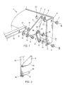
- FIGS. 1 and 2 there is illustrated a mounting assembly or cantilevered support means 1 having a first link or support member 2, second link or support member 8, and movable member 13.
- First link or support member 2 can be pivotally mounted to an upright support structure in the form of a mounting plate 3, pivoted about a first horizontal axis A.
- a pivot pin 4 can be inserted through apertures 6,7 and washer 5 to provide the pivotal mounting of the first link at a first end thereof about horizontal axis A.
- Second link or support member 8 can be pivotally mounted to plate 3 about a second horizontal axis B.
- a pivot pin 9 can be inserted through apertures 11, 12 and washer 10 to provide the pivotal mounting of the second link at a first end thereof about horizontal axis B.
- Angularly movable member 13 can be pivotally mounted to first support member 2 at a second end thereof about a third horizontal axis C. Again a pivot pin 14 can be inserted through apertures 16, 17 and a washer 15 can provide a pivotal mounting about horizontal axis C. Member 13 can be pivotally mounted to second support member 8 at a second end thereof about a horizontal axis D by a pivot pin 18 inserted through apertures 20, 21 and washer 19.
- pins 4, 9, 14 and 18 When pins 4, 9, 14 and 18 have been inserted as described above they may be fixed against being removed by their inserted ends being peened by any known method.
- First support member 2 may have a heel portion as shown which can provide a female engagement means or concavity 29 which can be engageable with an end of second support member 8 which provides a complementary male engagement means or convex end 30.
- Plate 3 may be provided with slotted apertures 22 for mounting to a wall or other support structure.
- the member 13 When disposed as in FIG. 1 the member 13 is in an operative or working position in which the lock, limit, stop or engagement means 29 and 30 may engage with each other.
- FIG. 2 illustrates the disposition of the support member 2 when in a stored position in which engagement means 29 and 30 are dis-engaged.
- Foldaway ironing board assembly 23 which is supported from an upright support structure such as a wall to which plate 3 is mounted by screws passing through slotted apertures 22.
- Foldaway ironing board assembly 23 can include an elongate ironing board member 24. mounted to a generally U-shaped bent tubular bar whose arms can provide two spaced apart angularly movable members 13 of two support means 1 each of which can be mounted to opposite ends of plate 3 as described above.
- Ironing board member 24 preferably includes a frame 25 and a planar ironing surface, ideally formed from an expanded metal grid 26.
- Ironing board member 24 is ideally foldable about at least one transverse axis T1 and preferably a cushioned cover 27 may cover grid 26.
- a storage cover 28 can also be provided and is preferably pivotally mounted to one end of parallel arms 31, the other end of arms 31 being pivotally mounted to plate 3.
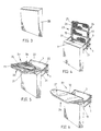
- foldaway ironing board assembly 23 When in a stored position, shown in FIG. 3, foldaway ironing board assembly 23 is covered by storage cover 28 which may have a magnetic catch (not shown).
- storage cover 28 When foldaway ironing board assembly 23 is desired to be used, storage cover 28 is moved to the position as shown in FIGS. 4 to 6. Ironing board member 23 is then pulled down from a vertical stored position shown in FIG. 4 to a horizontal position as shown in FIG. 5.
- both support means 1 move from the position as shown in FIG 2 to the position shown in FIG. 1 and thereby engagement means 29 and 30 become engaged thereby restraining movement of support means 1.
- Ironing board member 24 may then be unfolded about pivotal axis T1 to an operative position in which a longitudinal edge 32 is in close proximity to plate 3 and a portion of support means 1 extends between longitudinal edge 32 and the plate 3.
- ironing board assembly 23 When ironing board assembly 23 is no longer required to be used it can be stored by a reverse operation to that as described above.
- FIGS. 7 to 10 there is illustrated a second embodiment of a foldaway ironing board assembly 32. To avoid repetition the only differences between the above first embodiment will be described.
- a retractable cantilevered support means 34 can include support members 2,8 and plate 35 preferably mounted at unsupported ends of two telescopic arms 36 slidably mounted to respective runners 37 ideally located inside a support structure, which in this embodiment is an upright wall 39 of a storage area under a bench top 38.
- a further plate 35 can be mounted intermediate the ends of arms 36 and they are preferably pivotally mounted to each plate 35 on pairs of links or support members 2, 8.
- Member 40 of support means 34 is pivotally mounted to links 2,8.
- a threaded locking pin 41 for releasable engagement with a threaded aperture 42 on outer plate 35.
- Ironing board member 24 can be mounted to each angularly movable member 40 such that when in the operative position shown in FIG. 10, longitudinal edge 32 is in close proximity to the support structure upright wall 39 and a portion of support means 34 (i.e. a portion of arms 36) extends between upright wall 39 and longitudinal edge 32.
- the foldaway ironing board assembly 32 and the telescopic arms 36 are extended as shown in FIG. 8 .
- Ironing board member 24 is then rotated to through 90° as shown in FIG. 9 in which engagement means 29, 30 move from a disengaged relationship to an engaging relationship.
- Locking pin 41 may then be screwed into aperture 42 to provide a positive locking of ironing board assembly 32.
- the ironing board member 24 can be unfolded ready for use. When it is no longer required to be used assembly 33 can be stored by a reverse operation to that as described.
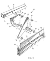
- a support means 50 which can include a first support member 51, second support member 57, third support member 63, movable member 62 and a retractable telescopic arm 52.
- First support member 51 is preferably pivotally mounted to retractable telescopic arm 52 about a first horizontal pivotal axis F.
- Pivot pin 53 inserted through apertures 55, 56 and washer 54 provides the pivotal mounting about horizontal axis F.
- Second support member 57 can be pivotally mounted to arm 52 about a second horizontal axis G.
- Pivot pin 58, inserted through apertures 60, 61 and washer 59 provide the pivotal mounting about horizontal axis G.
- First and third support members 51, 63 and movable member 62 are ideally pivotally mounted about a common horizontal axis H by pivot pin 64 inserted through apertures, 65, 66, 67 and washers 68.
- Further third support member 63 is ideally pivotally mounted to second support member 57 about a horizontal axis I by pivot pin 69 inserted through apertures 70, 71 and washer 72.
- pivot pins 53, 58, 63, 69 When pivot pins 53, 58, 63, 69 have been inserted as described, they may be fixed against being removed when their ends are peened.
- Third support member 63 has an arcuate slot 73 which can receive a pin 74 protruding from movable member 62. Furthermore first support member 51 can have a female engagement means 75 for engagement with a male engagement means 76 located at one end of second support member 57.
- FIG. 11 shows the assembly in an operative position in which pin 74 limits movement of movable member 62 by abutting end of arcuate track 73.
- moveable member has been rotated through 90° and therefore pin 74 has moved along arcuate track 73 to its end 73b .
- further rotation of third support member dis-engages engagement means 75, 76 as shown in FIG. 13 which thereby allows third support member to be rotated through another 90° resulting in 180° rotation in total.
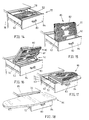
- FIGS. 14 to 18 there is illustrated a further embodiment of a foldaway ironing board assembly 77 which can be supported from a support structure such as supporting walls 78 of a sliding drawer assembly.
- Two retractable telescopic arms 52 of a respective cantilevered support means 50 are ideally slidably mounted to runners associated with a respective upright supporting wall 78.
- Foldaway ironing board assembly 77 can include an ironing board member 80 identical to that of FIGS. 3 to 6 and therefore to avoid repetition is not described again.
- Ironing board member 80 can be mounted to a wing comprising a bent tubular bar 81 with a handle 82 mounted thereto.
- Tubular bar 81 can be used to provide two third support members 62.
- foldaway ironing board assembly 77 has two support means 50 as described in FIGS. 11 to 13.
- a handle 83 mounted to front drawer wall 84 which is mounted to ends of telescopic arms 52 is used to pull arms 52 to the extended position shown in FIG. 14 when in this position each of support means 50 is in the position shown in FIG. 13.
- Handle 82 may then be used to rotate board member through 180° as shown in FIGS. 15, 16 and 17 in which 90° corresponds to the position shown in FIG. 12. Due to the arrangement of support means 50, lifting of board member 80 causes it to be raised to clear drawer wall 84. After board member 80 has been pivoted through 180° it is unfolded into an operative position ready for use as illustrated in FIG. 18. When in this position a longitudinal edge 32 is in close proximity of support structure 85. When it is no longer required to be used, assembly 77 can be stored by a reverse operation to that as described.
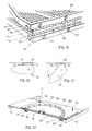
- a double hinge 90 is illustrated which can be mounted to board member 24 to provide pivotal movement about adjacent transverse axes T1 and T2. This therefore allows a space 91 to accommodate a cushioned cover 28 (not shown in FIG. 19) when sandwiched by board member 24 when in the folded position as shown. Further, there are tabs 92 protruding from frame 25 for engaging and holding cushioned cover 28 and protrusions 93 ensure a planar ironing surface is provided when board member 24 is unfolded to the operative position.
- pivot means 95 for selectively allowing limited rotation of board member 24 about a vertical axis J. Therefore board member 24 can be selectively rotated as illustrated by the arcuate arrowed line to positions other than edge 32 being parallel to support structure 96
- the pivot means as includes ball bearings 97 biassed by springs 98 mounted in an arcuate track 99 which is part of a base plate 100 mounted to , for example, the links of the above described mounting mechanism.
- Pivotally attached about vertical axis J is a rotatable plate 101 with an arcuate track 102 having apertures 103 therein for engagement with ball bearings 97.
- Bolts 104 allow for mounting of ironing board member 24 ( of FIG. 19) to rotatable plate 101 and selective positioning about vertical axis J of board member 24 is provided by rotation of plate 101 relative to base plate 100.
- ball bearings 97 engage apertures 103 to restrict pivotal movement when a desired position has been obtained.
- a height adjustment means 105 comprising a mounting plate 106 with a slot 107 punched therein. Along one longitudinal edge of slot 107 are a plurality of female engagement means in the form of recesses 109.
- Height adjustment means 105 can also include a moveable plate 110 which is held captive in slot 107 by tabs 111. At a lower end of plate 110 is a male engagement means in the form of protrusion 112 for engaging with one of recesses 109. Height adjustment means 105 can replace, for example, plate 3 as described in FIG. 1. Accordingly, first support member 2 and second support member 8 are pivotally mounted to plate 110 and height adjustment is effected by selective engagement of protrusion 112 with one of recesses 109. Once engaged the weight of ironing board member 24 assists in maintaining engagement of protrusion 112 in one of recesses 109.
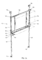
- Mount 115 for the foldaway ironing board assembly 23 illustrated in FIGS. 3 to 6.
- Mount 115 includes wall mounting means in the form of two pairs of spaced apertured plates 116 and two parallel upright tracks 117 each being mounted at its ends to one of plates 116.
- Mount 115 also includes an ironing board mounting means in the form of an apertured frame 118 slidably mounted to tracks 117.
- a lock 119 is pivotally mounted to frame 118.
- Lock 119 has a handle 120 biased by spring 121 to a locked position in which lock 119 grips tracks 117.
- pTo release frame 118 from the locked position handle 120 is pushed downwards and allows frame 118 to slide along tracks 117 to provide height adjustment of foldaway ironing board assembly 23 when mounted to frame 118.
- Collars 122 are fixed to respective tracks 117 and between an upper slidable frame mount 123 and a respective collar 122 there is mounted a spring 124 for biasing frame 118 to upper ends of tracks 117.
- mount 115 allows height adjustment of a mounted foldaway ironing board assembly 23 which is beneficial for a household of people with different heights in which one or more of the people may be confined to a wheelchair.
Landscapes
- Irons (AREA)
Claims (17)
- Montageanordnung (1, 50) für ein Glied (13, 62), durch die das Glied winkelförmig aus einer Lagerungsstellung in eine Arbeitsstellung bewegt werden kann, mit Folgendem:einem ersten Verbindungsglied (2, 51), das im Gebrauch so angeordnet ist, dass es an seinem ersten Ende an einem Verbindungspunkt davon schwenkbar an einer Stütze (3, 53, 52) und an seinem zweiten Ende schwenkbar an dem Glied (13, 62) angebracht werden soll, undeinem zweiten Verbindungsglied (8, 57), das im Gebrauch so angeordnet ist, dass es an seinem ersten Ende an einem von dem Verbindungspunkt des ersten Verbindungsglieds (2, 51) beabstandeten Punkt an der Stütze (3, 36, 52) schwenkbar an der Stütze (3, 36, 52) und an seinem zweiten Ende schwenkbar an dem Glied (13, 62) angebracht werden soll, dadurch gekennzeichnet, dassdas zweite Verbindungsglied (8, 57) im Gebrauch in der Arbeitsstellung des Glieds (13, 62) an einem Anschlag- oder Begrenzungsmittel (29, 75) an dem ersten Verbindungsglied (2, 51) zur Anlage kommt, um eine winkelförmige Bewegung des Glieds (13, 62) an der Arbeitsstellung vorbei zu verhindern, undim Gebrauch in der Arbeitsstellung des Glieds (13, 62) sowohl das zweite Ende des ersten Verbindungsglieds (2, 51) als auch das zweite Ende des zweiten Verbindungsglieds (8, 57) zwischen dem ersten Ende des ersten Verbindungsglieds (2, 51) und dem ersten Ende des zweiten Verbindungsglieds (8, 57) liegen.
- Montageanordnung nach Anspruch 1, bei der die zweiten Enden des ersten (2, 51) und des zweiten Verbindungsglieds (8, 57) im Gebrauch in der Arbeitsstellung des Glieds (13, 62) vertikal zwischen den ersten Enden des ersten (2, 51) und zweiten Verbindungsglieds (8, 57) liegen.
- Montageanordnung nach Anspruch 1, bei der die zweiten Enden des ersten (2, 51) und des zweiten Verbindungsglieds (8, 57) im Gebrauch in der Arbeitsstellung des Glieds (13, 62) horizontal zwischen den ersten Enden des ersten (2, 51) und zweiten Verbindungsglieds (8, 57) liegen.
- Montageanordnung für ein Glied nach einem vorhergehenden Anspruch, bei der das erste Verbindungsglied (51) an seinem zweiten Ende zusammen mit einer Platte (63) geschwenkt wird, die einen bogenförmigen Schlitz (73) aufweist, der zu dem Drehpunkt am zweiten Ende des ersten Verbindungsglieds (51) konzentrisch ist, wobei das zweite Verbindungsglied (57) an seinem zweiten Ende an einem an das Ende des Schlitzes (73) anschließenden Punkt schwenkbar mit der Platte (63) verbunden ist, wobei das Glied (62) mit einem in dem Schlitz (73) aufgenommenen Stift (74) ausgerüstet ist.
- Flügel mit einem Rand, um den er schwenkt, wobei der Flügel an jeweiligen Enden des Rands durch ein Paar Montageanordnungen (1, 50) nach Anspruch 1 angebracht ist.
- Flügel nach Anspruch 5, bei dem die Stütze (35) für das Paar Montageanordnungen (1, 50) auf Gleitschienen angebracht ist, sodass sie vor der Drehung in die Arbeitsstellung eine Translationsbewegung aus einer Lagerungsstellung durchführen kann.
- Flügel nach Anspruch 5 oder 6, wobei der Flügel ein drehbar angebrachtes planares Element (80) stützt.
- Flügel nach Anspruch 7, bei dem das planare Element (80) aus zwei Segmenten besteht, wobei das eine über ein Scharnier mit dem anderen verbunden ist, damit eine Bewegung aus einer zusammengeklappten Stellung in eine koplanare Anordnung erfolgen kann.
- Bügelbrett mit Folgendem:wobei die Montagemittel (1, 50) ein Paar beabstandeter Montageanordnungen umfassen, wobei jede Montageanordnung des Paars ein erstes (2, 51) und ein zweites (8, 57) Verbindungsglied aufweist, die an jeweiligen beabstandeten ersten Enden mit einer Stütze (3, 36, 52) und an jeweiligen beabstandeten zweiten Enden mit dem planaren Element (24, 80) verbunden sind, dadurch gekennzeichnet, dass bei jeder der Montageanordnungeneinem planaren Element (24, 80), das eine Bügelfläche bereitstellen soll; Montagemitteln (1, 50), dank derer das planare Element (24, 80) aus einer Lagerungsstellung in eine Arbeitsstellung bewegt werden kann;
das zweite Verbindungsglied (8, 57) ein Anschlagoder Begrenzungsmittel (29, 75) in Eingriff nimmt, das sich an dem ersten Verbindungsglied (2, 51) befindet und eine winkelförmige Bewegung der Bügelfläche an der Arbeitsstellung vorbei einschränkt, und
im Gebrauch in der Arbeitsstellung der Bügelfläche sowohl das zweite Ende des ersten als auch das zweite Ende des zweiten Verbindungsglieds zwischen dem ersten Ende des ersten Verbindungsglieds (2, 51) und dem ersten Ende des zweiten Verbindungsglieds (8, 57) liegen. - Bügelbrett nach Anspruch 9, bei dem bei jeder der Montageanordnungen die zweiten Enden des ersten (2, 51) und zweiten Verbindungsglieds (8, 57) im Gebrauch in der Arbeitsstellung der Bügelfläche vertikal zwischen den ersten Enden des ersten (2, 51) und zweiten Verbindungsglieds (8, 57) liegen.
- Bügelbrett nach Anspruch 9, bei dem bei jeder der Montageanordnungen die zweiten Enden des ersten (2, 51) und des zweiten Verbindungsglieds (8, 57) im Gebrauch in der Arbeitsstellung der Bügelfläche horizontal zwischen den ersten Enden des ersten (2, 51) und zweiten Verbindungsglieds (8, 57) liegen.
- Bügelbrett nach Anspruch 9, bei dem bei jeder der Montageanordnungen das Anschlag- oder Begrenzungsmittel (29, 75) am ersten Verbindungsglied (2, 51) angebracht ist und in der Arbeitsstellung mit dem ersten Ende des zweiten Verbindungsglieds (8, 57) in Eingriff kommt, wobei dieser Eingriff eine in eine komplementäre Höhlung (29, 75) an den entsprechenden in Eingriff kommenden Teilen hineinpassende konvexe Fläche (30, 76) umfasst.
- Bügelbrett nach einem der Ansprüche 9, 10 oder 12, bei dem sich das planare Element in seiner Lagerungsstellung vertikal in einem an einer Wand angebrachten Schrank befindet und das erste (2) und das zweite (8) Verbindungsglied sich von der Rückseite des Schranks erstrecken und das planare Element (24, 80) davon hochstellen, wobei das erste und zweite Verbindungsglied eine winkelförmige Bewegung in eine allgemein horizontale, aus dem Schrank herausragende Arbeitslage ermöglichen.
- Bügelbrett nach einem der Ansprüche 9, 10 oder 12, bei dem die Lagerungsstellung in einem Schrank ist, wobei es sich bei der Stütze (35) um einen Rahmen auf Schienen (37) handelt, der so angeordnet ist, dass er aus dem Schrank heraus in eine Stellung gezogen wird, in der das Brett winkelförmig in die Arbeitsstellung bewegt werden kann.
- Bügelbrett nach Anspruch 14, bei dem die Bügelfläche nicht auf den Verbindungsgliedern, sondern auf Stützarmen (36) gelagert ist, wodurch die Bügelfläche über den Rahmen in eine allgemein vertikale Lagerungsstellung an dessen Hinterseite bewegt werden kann.
- Bügelbrett nach Anspruch 9 oder 11, bei dem die Lagerungsstellung . in einer Schubladeneinheit ist und das planare Element (80) über das erste (51) und zweite (57) Verbindungsglied und eine dazwischen liegende, mit einem bogenförmigen und damit konzentrischen Schlitz (73) versehene Schwenkplatte (63), die an dem planaren Element (80) mit dem zweiten Ende des ersten Verbindungsglieds (51) schwenkbar verbunden ist, an deren Boden angebracht ist, wobei die Platte (63) mit dem zweiten Ende des zweiten Verbindungsglieds (57) schwenkbar verbunden ist und das planare Element (80) einen in den Schlitz (63) eingreifenden Stift (74) aufweist, damit das planare Element (80) in einer Lagerungsstellung in der Schubladeneinheit liegen und daraus nach oben in eine Arbeitsstellung herausgezogen werden kann, in der es sich aus der Schubladeneinheit heraus erstreckt.
- Bügelbrett nach Anspruch 16, bei dem das planare Element (24) mit einer Drehscheibe (95) versehen ist, an der ein zweiteiliges, mit einem Scharnier verbundenes Brett angeordnet ist, das die Bügelfläche bildet, die zur Lagerung in der Schublade zusammengeklappt werden kann.
Applications Claiming Priority (7)
| Application Number | Priority Date | Filing Date | Title |
|---|---|---|---|
| AUPN4147A AUPN414795A0 (en) | 1995-07-14 | 1995-07-14 | Foldaway ironing board assembly |
| AUPN4147/95 | 1995-07-14 | ||
| AUPN414795 | 1995-07-14 | ||
| AUPN4592A AUPN459295A0 (en) | 1995-08-04 | 1995-08-04 | Pivotal support assembly |
| AUPN459295 | 1995-08-04 | ||
| AUPN4592/95 | 1995-08-04 | ||
| PCT/AU1996/000443 WO1997004159A1 (en) | 1995-07-14 | 1996-07-15 | Pivotal support and foldaway wings |
Publications (3)
| Publication Number | Publication Date |
|---|---|
| EP0865528A1 EP0865528A1 (de) | 1998-09-23 |
| EP0865528A4 EP0865528A4 (de) | 1998-11-11 |
| EP0865528B1 true EP0865528B1 (de) | 2003-03-19 |
Family
ID=25644992
Family Applications (1)
| Application Number | Title | Priority Date | Filing Date |
|---|---|---|---|
| EP96922691A Expired - Lifetime EP0865528B1 (de) | 1995-07-14 | 1996-07-15 | Schwenkbare trageeinrichtung und entfaltbare panele |
Country Status (3)
| Country | Link |
|---|---|
| EP (1) | EP0865528B1 (de) |
| DE (1) | DE69626843T2 (de) |
| WO (1) | WO1997004159A1 (de) |
Families Citing this family (4)
| Publication number | Priority date | Publication date | Assignee | Title |
|---|---|---|---|---|
| DE19808772C2 (de) * | 1998-03-02 | 2001-09-20 | Fritz Goetz | Klappmöbel |
| US6883438B2 (en) | 1998-10-20 | 2005-04-26 | Garry William Allen | Mounting assembly |
| IT1398718B1 (it) * | 2010-02-18 | 2013-03-18 | Foppa Pedretti Spa | Asse da stiro ripiegabile |
| DE102014012050A1 (de) * | 2014-08-18 | 2016-02-18 | Erwin Stengele | Küchenmöbel mit einer Arbeitsplatte und einer Zusatz-Arbeitsplatte |
Family Cites Families (8)
| Publication number | Priority date | Publication date | Assignee | Title |
|---|---|---|---|---|
| US2298002A (en) * | 1941-03-12 | 1942-10-06 | Gridiron Steel Company | Cabinet ironing board |
| GB853043A (en) * | 1958-11-15 | 1960-11-02 | Bradley And Company Ltd | Improvements relating to ironing and like boards or tables |
| US3730107A (en) * | 1971-10-19 | 1973-05-01 | R Bergkamp | Folding bracket mechanism |
| US4437414A (en) * | 1981-09-24 | 1984-03-20 | Syroco, Inc. | Folding table for wall mounting |
| FR2609382B1 (fr) * | 1987-01-14 | 1990-10-12 | Craipeau Gaetan | Table du type escamotable |
| AU1852388A (en) * | 1987-06-30 | 1989-01-05 | Robinhood Industries Pty. Limited | Wall mounted folding table |
| SE463443B (sv) * | 1989-10-11 | 1990-11-26 | Pelly Ind Ab | Hopfaellbar strykbraeda |
| DE4330867C1 (de) * | 1993-09-11 | 1994-08-25 | Vauth Sagel Gmbh & Co | Ausziehbares Einbaubügelbrett |
-
1996
- 1996-07-15 DE DE69626843T patent/DE69626843T2/de not_active Expired - Fee Related
- 1996-07-15 EP EP96922691A patent/EP0865528B1/de not_active Expired - Lifetime
- 1996-07-15 WO PCT/AU1996/000443 patent/WO1997004159A1/en not_active Ceased
Also Published As
| Publication number | Publication date |
|---|---|
| WO1997004159A1 (en) | 1997-02-06 |
| EP0865528A4 (de) | 1998-11-11 |
| DE69626843D1 (de) | 2003-04-24 |
| DE69626843T2 (de) | 2003-12-04 |
| EP0865528A1 (de) | 1998-09-23 |
Similar Documents
| Publication | Publication Date | Title |
|---|---|---|
| US6484645B2 (en) | Pivotal support and foldaway wings | |
| US7341006B2 (en) | Folding table assembly | |
| US4480556A (en) | Adjustable folding ironing board | |
| US4606575A (en) | Lock release for folding table | |
| US8359982B2 (en) | Self-stowing support table with articulating arm | |
| US2992043A (en) | Foldable tables | |
| US2766089A (en) | Portable folding table with lock means | |
| PL194427B1 (pl) | Stół z obracanym blatem | |
| US4027600A (en) | Combination safety stop and down lock for folding tables | |
| US6883438B2 (en) | Mounting assembly | |
| AU741452B2 (en) | Folding stage | |
| JPH0757280B2 (ja) | 引出し可能な組付け形アイロン台 | |
| US2860383A (en) | Foldable platform | |
| US6772699B1 (en) | Folding picnic table | |
| JPH0339685B2 (de) | ||
| AU723662C (en) | Pivotal support and foldaway wings | |
| US2879120A (en) | Long two part folding table | |
| WO1997004159A1 (en) | Pivotal support and foldaway wings | |
| US7395765B1 (en) | Rotatable table and method of use | |
| US5927212A (en) | Table with folding leaves | |
| CN216494059U (zh) | 一种折叠桌板及其折叠支架 | |
| KR102423185B1 (ko) | 개량 힌지 어셈블리 | |
| CN216316232U (zh) | 一种可伸缩折叠桌桌架 | |
| US20040056518A1 (en) | Folding linkage | |
| US20070278363A1 (en) | Collapsible door painting support stand |
Legal Events
| Date | Code | Title | Description |
|---|---|---|---|
| PUAI | Public reference made under article 153(3) epc to a published international application that has entered the european phase |
Free format text: ORIGINAL CODE: 0009012 |
|
| 17P | Request for examination filed |
Effective date: 19980212 |
|
| AK | Designated contracting states |
Kind code of ref document: A1 Designated state(s): DE FR GB |
|
| A4 | Supplementary search report drawn up and despatched |
Effective date: 19980923 |
|
| AK | Designated contracting states |
Kind code of ref document: A4 Designated state(s): DE FR GB |
|
| 17Q | First examination report despatched |
Effective date: 20000306 |
|
| GRAG | Despatch of communication of intention to grant |
Free format text: ORIGINAL CODE: EPIDOS AGRA |
|
| GRAG | Despatch of communication of intention to grant |
Free format text: ORIGINAL CODE: EPIDOS AGRA |
|
| GRAG | Despatch of communication of intention to grant |
Free format text: ORIGINAL CODE: EPIDOS AGRA |
|
| GRAH | Despatch of communication of intention to grant a patent |
Free format text: ORIGINAL CODE: EPIDOS IGRA |
|
| RAP1 | Party data changed (applicant data changed or rights of an application transferred) |
Owner name: INTELLEC PTY LIMITED |
|
| GRAH | Despatch of communication of intention to grant a patent |
Free format text: ORIGINAL CODE: EPIDOS IGRA |
|
| GRAA | (expected) grant |
Free format text: ORIGINAL CODE: 0009210 |
|
| AK | Designated contracting states |
Designated state(s): DE FR GB |
|
| REG | Reference to a national code |
Ref country code: GB Ref legal event code: FG4D |
|
| REF | Corresponds to: |
Ref document number: 69626843 Country of ref document: DE Date of ref document: 20030424 Kind code of ref document: P |
|
| ET | Fr: translation filed | ||
| PLBE | No opposition filed within time limit |
Free format text: ORIGINAL CODE: 0009261 |
|
| STAA | Information on the status of an ep patent application or granted ep patent |
Free format text: STATUS: NO OPPOSITION FILED WITHIN TIME LIMIT |
|
| 26N | No opposition filed |
Effective date: 20031222 |
|
| PGFP | Annual fee paid to national office [announced via postgrant information from national office to epo] |
Ref country code: DE Payment date: 20080829 Year of fee payment: 13 |
|
| PGFP | Annual fee paid to national office [announced via postgrant information from national office to epo] |
Ref country code: FR Payment date: 20080903 Year of fee payment: 13 |
|
| PGFP | Annual fee paid to national office [announced via postgrant information from national office to epo] |
Ref country code: GB Payment date: 20080827 Year of fee payment: 13 |
|
| GBPC | Gb: european patent ceased through non-payment of renewal fee |
Effective date: 20090715 |
|
| REG | Reference to a national code |
Ref country code: FR Ref legal event code: ST Effective date: 20100331 |
|
| PG25 | Lapsed in a contracting state [announced via postgrant information from national office to epo] |
Ref country code: FR Free format text: LAPSE BECAUSE OF NON-PAYMENT OF DUE FEES Effective date: 20090731 |
|
| PG25 | Lapsed in a contracting state [announced via postgrant information from national office to epo] |
Ref country code: GB Free format text: LAPSE BECAUSE OF NON-PAYMENT OF DUE FEES Effective date: 20090715 |
|
| PG25 | Lapsed in a contracting state [announced via postgrant information from national office to epo] |
Ref country code: DE Free format text: LAPSE BECAUSE OF NON-PAYMENT OF DUE FEES Effective date: 20100202 |