EP0865577B1 - Turbomachines et leur procede de fabrication - Google Patents
Turbomachines et leur procede de fabrication Download PDFInfo
- Publication number
- EP0865577B1 EP0865577B1 EP95940361A EP95940361A EP0865577B1 EP 0865577 B1 EP0865577 B1 EP 0865577B1 EP 95940361 A EP95940361 A EP 95940361A EP 95940361 A EP95940361 A EP 95940361A EP 0865577 B1 EP0865577 B1 EP 0865577B1
- Authority
- EP
- European Patent Office
- Prior art keywords
- impeller
- meridional distance
- blade
- dimensional
- flow
- Prior art date
- Legal status (The legal status is an assumption and is not a legal conclusion. Google has not performed a legal analysis and makes no representation as to the accuracy of the status listed.)
- Expired - Lifetime
Links
- 238000004519 manufacturing process Methods 0.000 title claims description 14
- 230000002829 reductive effect Effects 0.000 claims description 79
- 230000003068 static effect Effects 0.000 claims description 78
- 239000012530 fluid Substances 0.000 claims description 69
- 238000009826 distribution Methods 0.000 claims description 67
- 238000013461 design Methods 0.000 claims description 46
- 230000003247 decreasing effect Effects 0.000 claims description 24
- 238000000926 separation method Methods 0.000 claims description 24
- 230000001419 dependent effect Effects 0.000 claims description 14
- 238000011156 evaluation Methods 0.000 claims description 3
- 238000012795 verification Methods 0.000 description 66
- 238000000034 method Methods 0.000 description 46
- 230000001629 suppression Effects 0.000 description 31
- 238000004364 calculation method Methods 0.000 description 12
- 230000006978 adaptation Effects 0.000 description 9
- 230000000694 effects Effects 0.000 description 9
- 230000009471 action Effects 0.000 description 8
- 239000007787 solid Substances 0.000 description 8
- 238000013459 approach Methods 0.000 description 7
- 230000000737 periodic effect Effects 0.000 description 5
- 238000011144 upstream manufacturing Methods 0.000 description 5
- 238000010586 diagram Methods 0.000 description 4
- 230000002093 peripheral effect Effects 0.000 description 4
- 230000008569 process Effects 0.000 description 4
- 230000015572 biosynthetic process Effects 0.000 description 3
- 238000007796 conventional method Methods 0.000 description 3
- 238000005206 flow analysis Methods 0.000 description 3
- 238000009472 formulation Methods 0.000 description 3
- 230000010354 integration Effects 0.000 description 3
- 239000000203 mixture Substances 0.000 description 3
- 230000036961 partial effect Effects 0.000 description 3
- 238000004458 analytical method Methods 0.000 description 2
- 230000002349 favourable effect Effects 0.000 description 2
- 239000007788 liquid Substances 0.000 description 2
- 230000007246 mechanism Effects 0.000 description 2
- 238000005457 optimization Methods 0.000 description 2
- 230000009467 reduction Effects 0.000 description 2
- 230000002441 reversible effect Effects 0.000 description 2
- 240000008042 Zea mays Species 0.000 description 1
- 235000005824 Zea mays ssp. parviglumis Nutrition 0.000 description 1
- 235000002017 Zea mays subsp mays Nutrition 0.000 description 1
- 238000007906 compression Methods 0.000 description 1
- 230000006835 compression Effects 0.000 description 1
- 235000005822 corn Nutrition 0.000 description 1
- 238000011161 development Methods 0.000 description 1
- 238000012854 evaluation process Methods 0.000 description 1
- 238000011835 investigation Methods 0.000 description 1
- 238000012986 modification Methods 0.000 description 1
- 230000004048 modification Effects 0.000 description 1
- 238000005086 pumping Methods 0.000 description 1
Images


Classifications
-
- F—MECHANICAL ENGINEERING; LIGHTING; HEATING; WEAPONS; BLASTING
- F04—POSITIVE - DISPLACEMENT MACHINES FOR LIQUIDS; PUMPS FOR LIQUIDS OR ELASTIC FLUIDS
- F04D—NON-POSITIVE-DISPLACEMENT PUMPS
- F04D29/00—Details, component parts, or accessories
- F04D29/66—Combating cavitation, whirls, noise, vibration or the like; Balancing
- F04D29/68—Combating cavitation, whirls, noise, vibration or the like; Balancing by influencing boundary layers
- F04D29/681—Combating cavitation, whirls, noise, vibration or the like; Balancing by influencing boundary layers especially adapted for elastic fluid pumps
-
- F—MECHANICAL ENGINEERING; LIGHTING; HEATING; WEAPONS; BLASTING
- F04—POSITIVE - DISPLACEMENT MACHINES FOR LIQUIDS; PUMPS FOR LIQUIDS OR ELASTIC FLUIDS
- F04D—NON-POSITIVE-DISPLACEMENT PUMPS
- F04D29/00—Details, component parts, or accessories
- F04D29/18—Rotors
- F04D29/22—Rotors specially for centrifugal pumps
- F04D29/2205—Conventional flow pattern
-
- F—MECHANICAL ENGINEERING; LIGHTING; HEATING; WEAPONS; BLASTING
- F04—POSITIVE - DISPLACEMENT MACHINES FOR LIQUIDS; PUMPS FOR LIQUIDS OR ELASTIC FLUIDS
- F04D—NON-POSITIVE-DISPLACEMENT PUMPS
- F04D29/00—Details, component parts, or accessories
- F04D29/26—Rotors specially for elastic fluids
- F04D29/28—Rotors specially for elastic fluids for centrifugal or helico-centrifugal pumps for radial-flow or helico-centrifugal pumps
- F04D29/284—Rotors specially for elastic fluids for centrifugal or helico-centrifugal pumps for radial-flow or helico-centrifugal pumps for compressors
Definitions
- the present invention relates to a turbomachinery and a method of manufacturing the turbomachinery which includes a centrifugal pump or a mixed flow pump for pumping liquid, a blower or a compressor for compression of gas, and more particularly to a turbomachinery having an impeller which has a fluid dynamically improved blade profile for suppressing meridional component of secondary flow, and a method of manufacturing such a turbomachinery.
- the secondary flow is defined as flow which has a velocity component perpendicular to the main flow.
- the total energy loss caused by the secondary flows is referred to as the secondary flow loss.
- the low energy fluid accumulated at a certain region in the flow channel may cause a flow separation in a large scale, thus producing positively sloped characteristic curve and hence preventing the stable operation of the turbomachine.
- the three-dimensional geometry of the impeller is defined as a meridional geometry formed by a hub surface and a shroud surface and a blade profile serving to transmit energy to fluid.
- meridional geometry various geometries including a centrifugal type, a mixed flow type and an axial flow type are selected in accordance with design specification, including flow rate, pressure head and rotational speed, which is required in the individual turbomachinery.
- N is the rotational speed in revolutions per minutes (rpm)
- Q is the flow rate in cubic meter per minute (m 3 /min)
- H is the head in meter (m) representing fluid energy which is imparted to the fluid by the turbomachinery.
- the specific speed is determined if the design specification is given, and the meridional geometry of the impeller can be suitably selected in accordance with the specific speed.
- Q is defined as volume flow rate, and in case of a compressor or the like, the volume flow rate at an impeller inlet is used for a compressible fluid whose volume is variable between the impeller inlet and the impeller exit.
- the inlet blade angle is determined by the assumed inlet velocity triangle at each spanwise location to match the inlet blade angle with the inlet flow angle.
- the exit blade angle is determined by the assumed exit velocity triangle at each spanwise location to satisfy the design head.
- the inlet and the exit velocity triangles are calculated from the meridional geometry and the design flow rate and the design head, but can be updated based on the results of flow calculation of the impeller.
- the design specification is input to determine the meridional geometry and the number of blades of the impeller.
- a plurality of surfaces of revolution is defined on a meridional flow passage, and the tangential co-ordinate f 0 of a blade camber line at a point on each of surfaces of revolution is specified based on the past experience.
- the location, where the tangential co-ordinate f o is specified, is selected at the leading edge or at the trailing edge of the impeller in many cases.
- specified location of the tangential co-ordinate f 0 is referred as the stacking condition.
- the blade angle at the impeller inlet is determined from the meridional geometry of the impeller obtained by the first step and design flow rate.
- the blade angle at the impeller exit is determined from the meridional geometry of the impeller obtained by the first step, and design head.
- a curve which connects smoothly the determined blade angle at the impeller inlet and the blade angle at the impeller exit is defined to determine the blade angle distribution along the location of non-dimensional meridional distance m.
- the three-dimensional geometry of the impeller is determined by adding a certain thickness to the determined blade camber line to allow the blade to have a mechanical strength.
- step of evaluating flow fields three-dimensional inviscid flow analysis which is a flow analysis without consideration of viscosity of fluid is applied to the three-dimensional geometry of the impeller determined by the third step, and a possibility of poor performance caused by a flow separation due to rapid deceleration of flow in the impeller is evaluated.
- steps from the second step to the fourth step are repeated until the expected result is achieved.
- the secondary flow in the impeller results from the action of Coriolis force caused by the rotation of the impeller and the effects of the streamline curvature.
- the secondary flow in the impeller is divided broadly into two categories, one of which is blade-to-blade secondary flow generated along a shroud surface or a hub surface, the other of which is the meridional component of secondary flow generated along the pressure surface or the suction surface of a blade.
- the purpose of the present invention is to suppress the meridional component of secondary flow in a centrifugal or a mixed flow turbomachine.
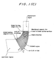
- Figs. 1(A) and 1(B) the three-dimensional geometry of a closed type impeller is schematically shown in Figs. 1(A) and 1(B) in such a state that most part of shroud surface is removed.
- Fig. 1(A) is a perspective view partly in section
- Fig. 1(B) is a cross-sectional view taken along a line A-A' which is a meridional cross-sectional view.
- a hub surface 2 extends radially outwardly from a rotating shaft 1 so that it has a curved surface similar to a corn surface.
- a plurality of blades 3 are provided on the hub surface 2 so that they extend radially outward from the rotating shaft 1 and are disposed at equal intervals in the circumferential direction.
- the blade tip 3a of the blades 3 are covered with a shroud surface 4 as shown in Fig. 1(B).
- a flow channel is defined by two blades 3 in confrontation with each other, the hub surface 2 and the shroud surface 4 so that fluid flows from an impeller inlet 6a toward an impeller exit 6b.
- the surface facing the rotational direction is the pressure surface 3b
- the opposite side of the pressure surface 3b is the suction surface 3c.
- a casing (not shown in the drawing) for enclosing the impeller 6 serves as the shroud surface 4. Therefore, there is no basic fluid dynamical difference between the open type impeller and the closed type impeller in terms of the generation and the suppression of the meridional component of secondary flows, thus only the closed type impeller will be described below.
- the impeller 6 having a plurality of blades 3 is incorporated as a main component, the rotating shaft 1 is coupled to a driving source, thereby jointly constituting a turbomachine. Fluid is introduced into the impeller inlet 6a through a suction pipe, pumped by the impeller 6 and discharged from the impeller exit 6b, and then delivered through a discharge pipe to the outside of the turbomachine.
- W is the relative velocity of flow
- R is the radius of streamline curvature
- ⁇ is the angular velocity of the impeller
- W ⁇ is the component in the circumferential direction of W relative to the rotating shaft 1
- p* is reduced static pressure
- p is static pressure
- ⁇ density of fluid
- u peripheral velocity at a certain radius r from the rotating shaft 1.
- the reduced static pressure p* has such a distribution in which the pressure is high at the hub side and low at the shroud side, so that the pressure gradient balances the centrifugal force W 2 /R and the Coriolis force 2 ⁇ W ⁇ directed toward the hub side.
- the meridional component of secondary flow is generated on both surfaces of the suction surface 3c and the pressure surface 3b.
- the secondary flow on the suction surface 3c has a greater influence on performance characteristics of turbomachinery.
- the purpose of the present invention is to suppress the meridional component of secondary flow on the suction surface of the blade.
- Fig. 2(B) which is a cross-sectional view taken along a line B-B' in Fig. 2(A)
- a pair of vortices which have a different swirl direction from each other are formed in the flow channel between two blades as the flow goes towards exit. These vortices are referred to as secondary vortices.
- a turbo machine having an impeller with a plurality of blades supported by a hub on which said blades are circumferentially spaced and covered by a shroud surface which forms an outer boundary to flow of fluid in a flow passage defining a flow direction between two adjacent blades, characterized in that:
- the present invention also provides a method of manufacturing a turbomachine having an impeller with a plurality of blades supported by a hub on which said blades are circumferentially spaced and covered by a shroud surface which forms an outer boundary to flow of fluid in a flow passage defining a flow direction between two adjacent blades, comprising:
- the Mach number slope at the shroud side MS-s may be selected to be not less than -0.8 as the lower limit of the Mach number slope at the shroud side MS-S, lim .
- the Mach number slope at the shroud side MS-S on the suction surface of the blade is defined as a gradient of Mach number on the shroud surface at the location between the non-dimensional meridional distance mm representing the above minimum value ⁇ mm of relative Mach number difference ⁇ M and the non-dimensional meridional distance mm-0.4 obtained by subtracting non-dimensional meridional distance 0.4 from non-dimensional meridional distance mm representing the above minimum value.
- the flow separation can be prevented in the downstream side of the location of non-dimensional meridional distance mm-0.4.
- the non-dimensional meridional distance mm representing the minimum value ⁇ Mm of relative Mach number ⁇ M is preferably selected to be in the range of non-dimensional meridional distance m-0.8-1.0.
- the pressure coefficient Cp is increased or decreased.
- the impeller is designed so that the above-mentioned characteristic decreasing tendency in the reduced static pressure difference ⁇ Cp or the relative Mach number difference ⁇ M between the hub and the shroud on the suction surface of the blade is realised, and further the above-mentioned characteristic limit in the pressure coefficient slope at the shroud side CPS-s or the Mach number slope at the shroud side MS-s on the suction surface of the blade is realised.
- the meridional component of secondary flow can be remarkably suppressed around and after the location of non-dimensional meridional distance mm-0.4 where the reduced static pressure difference ⁇ cp or the relative Mach number difference ⁇ M shows a remarkably decreasing tendency toward the impeller exit.
- the meridional component of secondary flow can be effectively suppressed in the overall area of the impeller.
- the pressure coefficient Cp is large at the shroud where reduced static pressure p* is low, and is small at the hub where reduced static pressure p* is high.
- the meridional component of secondary flow on the blade suction surface is directed to the shroud side having low reduced static pressure p* from the hub side having high reduced static pressure p*, suppression of meridional component of secondary flow can be expected by reducing pressure difference ⁇ Cp between them.
- the pressure coefficient Cp is equal to (W/Ut) 2 , where W is relative velocity.
- W relative velocity
- the physical variable being related to the behavior of secondary flow is relative Mach number.
- the present invention proposes the structure for suppressing meridional component of secondary flow on the suction surface of the blade, considering distribution of the pressure coefficient Cp mainly in the latter half of the impeller. That is, the blade profile is designed so as to have the pressure distribution so that the pressure difference ⁇ Cp between the shroud side and the hub side on the suction surface shows a remarkably decreasing tendency along the location of non-dimensional meridional distance m toward the impeller exit.
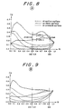
- Fig. 8 is a characteristic graph showing distribution of the pressure coefficient Cp obtained by the three-dimensional steady inviscid flow calculations, and thus the reduced static pressure difference ⁇ Cp of a pump according to a best mode of the first aspect of the present invention.
- the vertical axis represents the pressure coefficient Cp
- Fig. 8 the vertical axis represents the pressure coefficient Cp
- a solid curve at the upper part of the graph shows a pressure coefficient curve representing values of the pressure coefficient on the suction surface of the blade at the shroud side along the location of non-dimensional meridional distance m, and an alternative long and short dash curve extending substantially along the above solid line shows values of the pressure coefficient at the midpitch location on the shroud surface.
- a solid curve at the lower part of the graph shows a pressure coefficient curve representing values of the pressure coefficient on the suction surface of the blade at the hub side along the location of non-dimensional meridional distance m, and an alternative long and short dash curve extending substantially along the above solid line shows values of the pressure coefficient at the midpitch location on the hub surface.
- the distance between the solid curves adjacent to each other along the vertical axis i.e. the difference between a value on the pressure coefficient curve at the shroud side and a value on the pressure coefficient curve at the hub side at the same location of non-dimensional meridional distance m corresponds to the reduced static pressure difference ⁇ Cp.
- the gradient of inclined straight line which connects the value Cp s,m-0.4 on the pressure coefficient curve on the shroud surface at the location of non-dimensional meridional distance mm-0.4 and the value Cp s,m on the pressure coefficient curve on the shroud surface at the location of non-dimensional meridional distance mm, i.e. (Cp s,m -Cp s,m-0.4 )/0.4 is defined as a pressure coefficient slope at the shroud side CPS-s.
- the pressure coefficient slope at the shroud side CPS-s is negative.
- the gradient of straight line which connects the value Cp h,m-0.4 on the pressure coefficient curve on the hub surface at the location of non-dimensional meridional distance mm-0.4 and the value Cp h,m on the pressure coefficient curve on the hub surface at the location of non-dimensional meridional distance mm, i.e. (Cp h,m -Cp h,m-0.4 )/0.4 is defined as a pressure coefficient gradient at the hub side CPS-h.
- the pressure coefficient slope at the hub side CPS-h is positive.
- the difference between the value on the pressure coefficient curve at the shroud side at the location of non-dimensional meridional distance mm-0.4 and the value on the pressure coefficient curve at the hub side at the location of non-dimensional meridional distance mm-0.4 that is, the difference D between the reduced static pressure difference ⁇ Cp m-0.4 at the location of non-dimensional distance mm-0.4 and the minimum value ⁇ Cpm of the reduced static pressure difference ⁇ Cp is the essential factor which govern suppression of the secondary flow in the impeller of the turbomachinery.
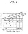
- the difference D is derived from cooperative contribution of the pressure coefficient slope at the shroud side CPS-s and the pressure coefficient slope at the hub side CPS-h, thus the differences D between the reduced static pressure difference ⁇ Cp m-0.4 at the location of non-dimensional meridional distance mm-0.4 and the minimum value ⁇ Cpm of the reduced static pressure difference ⁇ Cp in principal verification examples were plotted in Fig. 4 on the plane defined by horizontal and vertical axes representing the above respective slopes or gradients.
- the vertical axis represents the pressure coefficient slope at the shroud side CPS-s
- the horizontal axis represents the pressure coefficient slope at the hub side CPS-h.
- open symbols ( ⁇ , ⁇ , ⁇ ) represent adaptation to the quantitative criterion (describe latter) of judgement about suppression of the secondary flow
- solid symbols ( ⁇ , ⁇ , ⁇ ) represent nonadaptation to the above criterion.
- Fig. 7(A) is a table showing data in principal verification examples.
- Concerning four examples A, B, C and D, four pairs of data as to values of the pressure coefficient slope at the shroud side CPS-s and the pressure coefficient slope at the hub side CPS-h were read from the pressure coefficient curves of the verification examples shown in Figs. 8 through 11 in the order of A, B, C and D, and four ⁇ symbols were plotted on the plane between two axes from the readings.
- Concerning two examples 1 and 2 the pressure coefficient curves in the verification examples are not shown, but the resultant data were represented for reference as a part of large amount of other verification examples.
- open and solid symbols represent adaptation or nonadaptation to the quantitative criterion of judgement about suppression of the secondary flow.
- the quantitative criterion of judgement will be described below.
- Fig. 1(C) is an explanatory view used for the three-dimensional viscous flow calculation and showing the relationship between the computational meshes inside the bladed region and the secondary flow angle ⁇ defined in each of the computational meshes. Since the secondary flow is defined as flow which has a velocity component deviating from the direction of the computational mesh, the computational mesh to be used as a basis is required to have a certain regularity. That is, mesh is divided regularly (i.e.
- MSF-angle used as the quantitative criterion of judgement about suppression of the secondary flow is expressed by the following equation.
- ⁇ is an angle between the tangential direction along the streamwise mesh ( J direction) and the direction of meridional velocity vector at the location near the suction surface of the blade in each computational mesh in the bladed region in Fig.
- V m is meridional velocity
- s is non-dimensional meridional span length in K direction, s being 0 on the hub surface and 1 on the shroud surface on each of Jth Quasi-orthogonal line (mesh line of K direction);
- m is non-dimensional meridional distance in J direction, m being 0 at the blade leading edge and 1 at the blade trailing edge on each of Kth stream surface;
- [ ] ss is integrated value in the first mesh from the suction surface of the blade.
- MSF-angle is defined as mass-averaged value of the magnitude of the flow deviation angle from the streamwise mesh direction over the entire suction surface of the blade.
- the value of MSF-angle in each of verification example equal to or larger than the value of MSF-angle as the criterion of judgement means nonadaptation to the above criterion of judgement (insufficient action of secondary flow suppression)
- the value of MSF-angle in each of verification example smaller than the value of MSF-angle as the criterion of judgement means adaptation to the above criterion of judgement (sufficient action of secondary-flow suppression).
- the data of the nonadaptation are shown by solid symbols, and the data of the adaptation are shown by open symbols in Fig. 4.
- a boundary line between data area of solid symbols which show nonadaptation to the criterion and data area of open symbols which show adaptation to the criterion can be drawn on the basis of data plotted in Fig. 4 for each of specific speeds Ns.
- data area located at the lower right side of the boundary line corresponds to data area of adaptation to the criterion.
- data area of open symbols which are suitable for suppression of the secondary flow on the plane between the pressure coefficient slope at the shroud side CPS-s and the pressure coefficient slope at the hub side CPS-h means that the difference D between ⁇ Cp m-0.4 at the location of non-dimensional meridional distance mm-0.4 and the minimum value ⁇ Cpm of the reduced static pressure difference ⁇ Cp at the location of non-dimensional meridional distance mm can not be less than a certain value which is dependent on the criterion of judgement about suppression of the secondary flow.
- the value of the difference D is the result of cooperative contribution of the value of the pressure coefficient slope at the shroud side CPS-s on the vertical axis on the boundary line and the value of the pressure coefficient slope at the hub side CPS-h on the horizontal axis.
- the degree of contribution of both slopes varies in a wide range; there are three cases, i.e. the first case (1) which is largely dependent on the decreasing tendency of the pressure coefficient slope at the shroud side, the second case (2) which is dependent on the increasing tendency of the pressure coefficient slope at the hub side, and the third case (3) which is dependent on moderate harmonization of the decreasing tendency and the increasing tendency of both slopes.
- the first case (1) which is largely dependent on the decreasing tendency of the pressure coefficient slope at the shroud side
- the second case (2) which is dependent on the increasing tendency of the pressure coefficient slope at the hub side
- the third case (3) which is dependent on moderate harmonization of the decreasing tendency and the increasing tendency of both slopes.
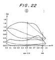
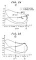
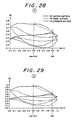
- Fig. 23 is a flow vector diagram showing the state of flow separation in the verification example of O.
- the pressure coefficient slope at the shroud side CPS-s and the pressure coefficient slope at the hub side CPS-h correspond to the Mach number slope at the shroud side MS-s and the Mach number slope at the hub side MS-h, respectively.
- the plane in Fig. 5 is defined by a vertical axis representing the Mach number slope at the shroud side MS-s and a horizontal line representing the Mach number slope at the hub side MS-h.
- Fig. 30 is a flow vector diagram showing the state of flow separation in the verification example of U.
- the D 280 value is lower than D 400 and D 560 value
- D 400 value is lower than D 560 value. So, the critical value of D has a tendency to have lower value for an impeller having a lower specific speed, although the quantitative dependency on the specific speed is not clear in Fig. 4 (the quantitative dependency is clarified in the following second aspect of the present invention).
- the impeller having suppressed meridional secondary flow
- the boundary lines of the inclined straight lines are confirmed and drawn in Fig. 4 or Fig. 5 dispersively for each of the specific speeds of the turbomachinery or sorts of fluid (incompressible fluid or compressible fluid), and the dependence of data on the specific speed is not made evident quantitatively.
- the turbomachinery having a certain specific speed and handling a certain kind of fluid when designing suitably the contribution in the pressure coefficient slope at the shroud side CPS-s and the pressure coefficient slope at the hub side CPS-h or the Mach number slope at the shroud side MS-s and the Mach number slope at the hub side MS-h from the aspect of secondary flow suppression so that the difference D between a minimum value ⁇ Cpm of the reduced static pressure difference ⁇ Cp and the value ⁇ Cp m-0.4 of the reduced static pressure difference ⁇ Cp at the location corresponding to non-dimensional meridional distance mm-0.4 obtained by subtracting non-dimensional meridional distance 0.4 from non-dimensional meridional distance mm representing the minimum value ⁇ Cpm or the difference DM between the minimum value ⁇ Mm of the relative Mach number difference ⁇ M and a value ⁇ M m-0.4 of the relative Mach number difference ⁇ M at the location corresponding to non-dimensional meridional distance obtained by subtracting non-dimensional meridional distance 0.4 from non-dimensional
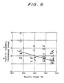
- the second aspect of the present invention with respect to the difference D between a minimum value ⁇ Cpm of the reduced static pressure difference ⁇ Cp and a value ⁇ Cp m-0.4 of the reduced static pressure difference ⁇ Cp or the difference DM between a minimum value ⁇ Mm of the relative Mach number difference ⁇ M and a value ⁇ M m-0.4 of the relative Mach number difference ⁇ M, the dependence on the specific speed is clarified in spite of sorts of fluid. That is, concerning the difference D or DM, the pressure coefficient Cp* which is normalized by the pressure coefficient Cp,mid-mid in the center of fluid passage is introduced and newly defined, whereby the boundary line according to the first aspect of the present invention can be expressed as a function of the specific spee Ns.
- Fig. 6 shows the plotted data about the above difference on the basis of the normalized pressure difference Cp* in verification examples.
- the vertical axis represents the difference D* between the normalized reduced static pressure difference ⁇ Cp* m-0.4 at the location of non-dimensional meridional distance mm-0.4 and a minimum value ⁇ Cp*m the normalized reduced static pressure difference ⁇ Cp* at the location of non-dimensional meridional distance mm
- the horizontal axis represents a specific speed Ns of the turbomachinery.
- Data plotted on the plane defined by both axes are the same as the data plotted on the plane of Figs. 4 and 5.
- a boundary line of an negatively sloped straight line can be drawn so that data shown by open symbols representing adaptation to the quantitative criterion of judgement about suppression of the secondary flow are located on the data area at the upper right of the drawing, and data shown by solid. symbols representing nonadaptation to the quantitative criterion of judgement about suppression of the secondary flow are located on the data area at the lower left of the drawing.
- the relative Mach number M can be related to the pressure coefficient Cp by the following equation, thus the normalized pressure coefficient Cp* is applicable to every kinds of fluid.
- the design method comprises a first step of determining the meridional geometry, a second step of determining the blade loading distribution, a third step of determining blade profile, a fourth step of judging the optimum reduced static pressure difference ⁇ Cp and the like, and a fifth step of evaluating flow fields.
- the pressure coefficient Cp is increased or decreased.
- the three-dimensional shape of the impeller which realize a characteristic distribution characterized by the first and second aspects of the present invention is determined.
- the design method is processed by the flow chart shown in Fig. 3(B).
- the meridional shape of hub and the shroud and the position of the leading edge of the blade and the trailing edge of the blade are defined, and the number of blades of the impeller is selected.
- Mesh required for numerical calculation is formed at an equal interval or unequal interval along the hub and the shroud surfaces. This mesh is extended to the upstream of the leading edge of the blade and the downstream of the trailing edge of the blade. The mesh is similar to that in Fig. 1(C) of the mesh for viscous flow calculations.
- Quasi-Orthogonal line (Q-O line) is drawn by connecting the corresponding points on the hub and the shroud.
- a plurality of surfaces of revolution is defined in the meridional flow channel, and the stacking condition f 0 (tangential co-ordinate of the blade camber line at a point on each of surfaces of revolution).
- the process in the first step is essentially the same as the process in the first step of the conventional design method shown in Fig. 3(A).
- the shape of the blade loading distribution ⁇ (r V ⁇ )/ ⁇ m is selected so that the blade loading distribution has a peak on the shroud surface in the first half of the non-dimensional meridional distance m along the shroud and a peak on the hub surface in the latter half of the non-dimensional meridional distance m along the hub.
- the distribution of ⁇ (r V ⁇ )/ ⁇ m along the hub and shroud is integrated along the non-dimensional meridional distance m to determine r V ⁇ distribution.
- the resultant value on the hub and the shroud surfaces obtained by integration along the non-dimensional meridional distance m is adjusted to satisfy the exit velocity triangles (i.e.
- V ⁇ values on the hub and the shroud at the impeller exit determined, in the similar manner as the conventional method, from the design head of the impeller), and the r V ⁇ distribution between the hub and the shroud is determined by the linear interpolation along Q-O line determined by the first step.
- the blade camber line is obtained by applying the condition that the velocity is along the blade at the blade camber line, i.e. there is no flow through the blade camber.
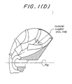
- f the tangential co-ordinate of the blade camber line (or wrap angle)
- ⁇ the tangential co-ordinate of cylindrical polar co-ordinate system
- B the number of blades (as shown in Fig. 1(E)).
- the above equation is a first order hyperbolic partial differential equation.
- the value of f o along an arbitrary Q-O line in the blade (the stacking condition) is used as initial value, and the above equation is integrated along the non-dimensional meridional distance m, and the tangential co-ordinate of the blade camber line f in the location of non-dimensional meridional distance m is determined.
- the three-dimensional geometry of the impeller is determined by adding a certain thickness to the determined blade camber line to allow the blade to have required mechanical strength.
- the stacking condition can be specified by, for example, setting the zero value of f 0 along the Q-O line at the blade trailing edge, or setting a moderate distribution of f 0 value along the Q-O line at the blade trailing edge.
- the velocity field is split into a tangentially-averaged and tangentially periodic components.
- the radial and axial velocities ( V r and V z, respectively) are expressed in terms of a stream function in order to satisfy the continuity (or mass conservation) equation of fluid dynamics.
- a Poisson type partial differential equation governing the streamfunction is obtained by using a suitable equation for the vorticity field generated by the action of the blades, which in turn is related to the blade circulation 2 ⁇ r V ⁇ .
- This equation can then be integrated by any suitable numerical method subject to uniform velocity condition at upstream and downstream boundaries and no flow (or constant stream function) conditions at the hub and shroud walls. Integration of this equation will give the values of streamfunction from which V r and V z are obtained.
- the velocity terms v rb1 , v zb1 and v ⁇ b1 are obtained from the solution of the tangentially periodic flow.
- the Clebsch formulation of the velocity field is used for the solution of the periodic flow.
- the velocity field is split into an unknown irrotational part (represented by a velocity potential function) and a known rotational part which is related to the blade circulation 2 ⁇ r V ⁇ .
- the governing equation of the unknown potential function is then found by using Clebsch formulation for the velocity field in the continuity equation of the periodic flow. In this way a 3D Poisson's equation is obtained which can then be integrated by a suitable numerical technique, subject to vanishing periodic tangential velocity and spanwise velocity at upstream and downstream boundaries and no-flow conditions through the hub and shroud surface.
- velocity field as well as blade loading of the impeller i.e. the pressure difference p(+) - p(-) between the pressure p(+) on pressure surface and the pressure p(-) on the suction surface of the blade can be obtained in the following equation.
- ⁇ p(+) - p(-) ⁇ / ⁇ 2 ⁇ (W b1 • ⁇ r V ⁇ )/B, where W b1 is relative velocity at the location on blade surface.
- the normalized pressure coefficient Cp* is defined as follows.
- Cp* Cp/Cp,mid-mid where Cp,mid-mid is the pressure coefficient at the center of the flow channel (midspan and midpitch) at the location of non-dimensional meridional distance m.
- the pressure coefficient Cp in compressible fluid is defined in the following equation.
- the fourth step (a step of judging optimum reduced static pressure difference ⁇ Cp and the like), it is judged whether or not the distribution of the reduced static pressure difference ⁇ Cp or the relative Mach number difference ⁇ M along the location of non-dimensional meridional distance m calculated in the third step is suitable for suppression of the secondary flow in the impeller.
- the decreasing tendency in the reduced static pressure difference ⁇ Cp is realized by (a) the degree of dependence on a variation at the shroud side, (b) the degree of dependence on a variation at the hub side, and (c) the degree of dependence on both variation at the shroud side and the hub side.
- the pressure coefficient slope on the suction surface of the blade at the shroud side CPS-s and the pressure coefficient slope on the suction surface of the blade at the hub side CPS-h between the location of a minimum value ⁇ Cpm of the reduced static pressure difference ⁇ Cp and the location of non-dimensional meridional distance mm-0.4 obtained by subtracting non-dimensional meridional distance 0.4 from non-dimensional meridional distance mm representing the minimum value ⁇ Cpm are defined, and it is judged whether this value satisfies the criteria defined in the first aspect of the present invention.
- the pressure coefficient Cp is equal to (W/U) 2 , where W is relative velocity.
- W is relative velocity.
- the physical variable related to the behavior of secondary flow is relative Mach number. Therefore, in case of compressible fluid, the same judgement concerning the reduced static pressure difference ⁇ Cp is applied to the relative Mach number difference ⁇ M based on the criteria defined in the first aspect of the present invention.
- the fifth step step of evaluation of flow fields
- a possibility of poor performance caused by the flow separation due to rapid deceleration or rapid pressure increase in the impeller determined by the third step is evaluated.
- the steps from the second step to the fifth step are repeated until the expected result is achieved.
- the characteristics of flow fields i.e. the blade loading distribution directly related to the flow physics, is used as input data for the third step to determine the blade profile, therefore the blade profile for suppressing the secondary flow can be promptly designed and the impeller having such blade profile can be easily manufactured, compared with the conventional manufacturing method using the modification of blade angle distribution by trial and error.
- a turbomachinery having an impeller, characterized in that the impeller is designed so that the reduced static pressure difference ⁇ Cp or the relative Mach number difference ⁇ M between the hub and the shroud on the suction surface of a blade shows a remarkably decreasing tendency along the location of non-dimensional meridional distance m toward the impeller exit.
- the meridional component of secondary flow can be effectively suppressed, a loss which occurs in the turbomachinery or the down stream flow channel can be reduced, emergence of positively sloped characteristic curve can be avoided, and stability of operation can be improved. Therefore, the present invention has a great utility value in industry.
Landscapes
- Engineering & Computer Science (AREA)
- Mechanical Engineering (AREA)
- General Engineering & Computer Science (AREA)
- Structures Of Non-Positive Displacement Pumps (AREA)
Claims (10)
- Turbomachine possédant une roue ayant plusieurs ailettes supportées par un moyeu sur lequel les ailettes sont espacées circonférentiellement et recouvertes d'une surface de carénage qui forme une limite externe à l'écoulement de fluide formé dans un passage d'écoulement délimitant une direction d'écoulement entre deux ailettes adjacentes, caractérisée en ce que :la roue a une configuration telle qu'une différence réduite de pression statique ΔCp ou une différence relative de nombre de Mach ΔM entre le moyeu et le carénage à la surface d'aspiration de l'ailette présente une tendance qui diminue remarquablement le long de l'emplacement d'une distance méridionale sans dimension m vers la sortie de la roue et est sélectionnée afin qu'elle soit inférieure à une valeur spécifiée qui dépend de la vitesse spécifique Ns de la turbomachine, la vitesse spécifique Ns étant définie par la relation Ns = NQ0,5/H0,75, N étant la vitesse de rotation en tours par minute, Q le débit à une entrée de la roue, en mètres cubes par minute, et H la hauteur en mètres représentant l'énergie du fluide qui est donnée au fluide par la turbomachine,la tendance qui diminue remarquablement de ΔCp de la turbomachine qui transmet un fluide incompressible est telle que la différence réduite de pression statique entre une valeur minimale ΔCpm de la différence réduite de pression statique ΔCp et une valeur ΔCpmm-0,4 de la différence réduite de pression statique ΔCp à un emplacement correspondant à la distance méridionale sans dimension mm-0,4, obtenue par soustraction d'une distance méridionale sans dimension 0,4 de la distance méridionale sans dimension mm qui représente la valeur minimale ΔCpm est sélectionnée afin queelle ne soit pas inférieure à 0,20 à la vitesse spécifique Ns qui ne dépasse pas 280,elle ne soit pas inférieure à 0,28 à la vitesse spécifique Ns qui ne dépasse pas 400, etelle ne soit pas inférieure à 0,35 à la vitesse spécifique Ns qui ne dépasse 560, etla tendance qui diminue remarquablement de ΔM pour la turbomachine qui transmet un fluide compressible est telle que la différence relative de nombre de Mach entre la valeur minimale ΔMm de la différence relative de nombre de Mach ΔM et une valeur ΔMm-0,4 de la différence relative de nombre de Mach ΔM à l'emplacement correspondant à la distance méridionale sans dimension Mm-0,4 obtenue par soustraction d'une distance méridionale sans dimension 0,4 de la distance méridionale sans dimension M2 représentant la valeur minimale ΔMm est sélectionnée afin qu'elle ne soit pas inférieure à 0,23 à la vitesse spécifique qui ne dépasse pas 488.
- Turbomachine selon la revendication 1, dans laquelle la distance méridionale sans dimension Mm représentant la valeur minimale ΔCpm de la différence réduite de pression statique ΔCp est sélectionnée afin qu'elle soit comprise dans la plage de distance méridionale sans dimension m = 0 à 8,0.
- Turbomachine selon la revendication 1 ou 2, dans laquelle la pente du coefficient de pression du côté du carénage CPS-s à la surface d'aspiration de l'ailette est sélectionnée afin qu'elle ne soit pas inférieure à -1,3 à une limite inférieure de la pente du coefficient de pression du côté du carénage CPS-s,LIM.
- Turbomachine selon la revendication 1, dans laquelle la pente du nombre de Mach du côté du carénage MS-s du côté d'aspiration de l'ailette est sélectionnée afin qu'elle ne soit pas inférieure à -0,8 formant la limite inférieure de la pente du nombre de Mach du côté du carénage Ms-s,LIM.
- Turbomachine selon la revendication 1 ou 4, dans laquelle la distance méridionale sans dimension M2 représentant la valeur minimale ΔM de la différence relative de nombre de Mach ΔM est sélectionnée afin qu'elle soit comprise dans la plage de distance méridionale sans dimension m = 0,8 à 1,0.
- Procédé de fabrication d'une turbomachine possédant une roue ayant plusieurs ailettes supportées par un moyeu sur lequel les ailettes sont espacées circonférentiellement et recouvertes d'une surface de carénage qui forme une limite extérieure pour l'écoulement d'un fluide dans un passage d'écoulement délimitant une direction d'écoulement entre deux ailettes adjacentes, comprenant :dans lequel une différence réduite de pression statique ΔCp ou une différence relative de nombre de Mach ΔM entre le moyeu et le carénage à la surface d'aspiration de l'ailette présente une tendance qui diminue remarquablement le long de l'emplacement d'une distance méridionale sans dimension m vers la sortie de la roue et est sélectionnée afin qu'elle soit inférieure à une valeur spécifiée qui dépend de la vitesse spécifique Ns de la turbomachine, la vitesse spécifique Ns étant définie par la relation Ns = NQ0,5/H0,75, N étant la vitesse de rotation en tours par minute, Q le débit à une entrée de la roue, en mètres cubes par minute, et H la hauteur en mètres représentant l'énergie du fluide qui est donnée au fluide par la turbomachine,une première étape de sélection d'une géométrie méridionale et du nombre d'ailettes de la roue à l'aide de spécifications de conception telles que des données d'entrée, délimitant plusieurs surfaces de révolution dans un canal d'écoulement méridional, et la détermination d'une condition d'empilement fo,une seconde étape de détermination d'une distribution de charge d'ailette rV suivant une distance méridionale sans dimension m par sélection d'une forme de la distribution de charge d'ailette δ(rV)/δm qui a un pic à la surface de carénage dans la première moitié de l'emplacement de la distance non méridionale m et un pic à la surface de moyeu dans la dernière moitié de l'emplacement de la distance méridionale sans dimension, et d'ajustement d'une valeur obtenue par intégration de la distribution de charge d'ailette le long de la distance méridionale sans dimension m afin que la hauteur nominale de la roue soit obtenue,une troisième étape de détermination d'une géométrie tridimensionnelle de la roue par intégration deune quatrième étape de détermination du fait que l'une des distributions de différence réduite de pression statique ΔCp et de distribution de différence relative de nombre de Mach ΔM le long de la distance méridionale sans dimension m obtenue dans la troisième étape convient ou non à la suppression de l'écoulement secondaire dans la roue,une cinquième étape d'évaluation de la possibilité de mauvaises performances dues à au moins une séparation de l'écoulement dans la roue, déterminée par la troisième étape, d'évaluation de l'écoulement secondaire dans la roue par un paramètre d'écoulement secondaire puis, après retour à la seconde étape pour la modification de la distribution de charge d'ailette d'après l'évaluation précédente, de répétition des étapes précédentes jusqu'à ce que le résultat prévu soit obtenu,
la tendance qui diminue remarquablement de ΔCp de la turbomachine qui transmet un fluide incompressible est telle que la différence réduite de pression statique entre une valeur minimale ΔCpm de la différence réduite de pression statique ΔCp et une valeur ΔCpmm-0,4 de la différence réduite de pression statique ΔCp à un emplacement correspondant à la distance méridionale sans dimension mm-0,4, obtenue par soustraction d'une distance méridionale sans dimension 0,4 de la distance méridionale sans dimension mm qui représente la valeur minimale ΔCpm est sélectionnée afin que
elle ne soit pas inférieure à 0,20 à la vitesse spécifique Ns qui ne dépasse pas 280,
elle ne soit pas inférieure à 0,28 à la vitesse spécifique Ns qui ne dépasse pas 400, et
elle ne soit pas inférieure à 0,35 à la vitesse spécifique Ns qui ne dépasse 560, et
la tendance qui diminue remarquablement de ΔM pour la turbomachine qui transmet un fluide compressible est telle que la différence relative de nombre de Mach entre la valeur minimale ΔMm de la différence relative de nombre de Mach ΔM et une valeur ΔMm-0,4 de la différence relative de nombre de Mach ΔM à l'emplacement correspondant à la distance méridionale sans dimension Mm-0,4 obtenue par soustraction d'une distance méridionale sans dimension 0,4 de la distance méridionale sans dimension M2 représentant la valeur minimale ΔMm est sélectionnée afin qu'elle ne soit pas inférieure à 0,23 à la vitesse spécifique qui ne dépasse pas 488. - Procédé de fabrication d'une turbomachine selon la revendication 6, dans lequel il est déterminé si la distance méridionale sans dimension mm représentant la valeur minimale ΔCpm de la différence réduite de pression statique ΔCp se trouve dans la plage de distance méridionale sans dimension m = 0,8 à 1 ou non.
- Procédé de fabrication d'une turbomachine selon la revendication 6 ou 7, dans lequel il est déterminé si la pente du coefficient de pression du côté du carénage CPS-s à la surface d'aspiration de l'ailette n'est pas inférieure à -1,3 formant la limite inférieure de la pente du coefficient de pression du côté du carénage CPS-s,LIM ou non.
- Procédé de fabrication d'une turbomachine selon la revendication 6, dans lequel il est déterminé si la pente du nombre de Mach du côté du carénage MS-s à la surface d'aspiration de l'ailette n'est pas inférieure à -0,8 formant la limite inférieure de la pente du nombre de Mach du côté du carénage MS-S,LIM ou non.
- Procédé de fabrication d'une turbomachine selon la revendication 6 ou 9, dans lequel il est déterminé si la distance méridionale sans dimension mm représentant la valeur minimale ΔMm de la différence relative de nombre de Mach ΔM est comprise dans la plage de distance méridionale sans dimension m = 0,8 à 1,0 ou non.
Applications Claiming Priority (2)
| Application Number | Priority Date | Filing Date | Title |
|---|---|---|---|
| CA002218692A CA2218692C (fr) | 1995-12-07 | 1995-12-07 | Turbomachines et leur procede de fabrication |
| PCT/GB1995/002904 WO1997021035A1 (fr) | 1995-12-07 | 1995-12-07 | Turbomachines et leur procede de fabrication |
Publications (2)
| Publication Number | Publication Date |
|---|---|
| EP0865577A1 EP0865577A1 (fr) | 1998-09-23 |
| EP0865577B1 true EP0865577B1 (fr) | 2002-07-03 |
Family
ID=25679742
Family Applications (1)
| Application Number | Title | Priority Date | Filing Date |
|---|---|---|---|
| EP95940361A Expired - Lifetime EP0865577B1 (fr) | 1995-12-07 | 1995-12-07 | Turbomachines et leur procede de fabrication |
Country Status (3)
| Country | Link |
|---|---|
| EP (1) | EP0865577B1 (fr) |
| CA (1) | CA2218692C (fr) |
| WO (1) | WO1997021035A1 (fr) |
Cited By (3)
| Publication number | Priority date | Publication date | Assignee | Title |
|---|---|---|---|---|
| EP1715117A2 (fr) | 2005-02-05 | 2006-10-25 | rewalux Markisenvertrieb GmbH | Protection réglable contre le soleil avec une bâche |
| US10962021B2 (en) | 2018-08-17 | 2021-03-30 | Rolls-Royce Corporation | Non-axisymmetric impeller hub flowpath |
| EP4033047A1 (fr) | 2021-01-22 | 2022-07-27 | Warema Renkhoff SEd | Installation de protection solaire doté d'un système de tirage |
Families Citing this family (5)
| Publication number | Priority date | Publication date | Assignee | Title |
|---|---|---|---|---|
| KR101001056B1 (ko) | 2010-02-19 | 2010-12-14 | 송길봉 | 구심력 동작형 수차 |
| JP5611307B2 (ja) * | 2012-11-06 | 2014-10-22 | 三菱重工業株式会社 | 遠心回転機械のインペラ、遠心回転機械 |
| CN114251129B (zh) * | 2021-11-29 | 2024-06-14 | 中国船舶工业集团公司第七0八研究所 | 用于透平机械二次流分析评估第三类流面及其设计方法 |
| CN116306180B (zh) * | 2023-05-22 | 2023-08-01 | 陕西空天信息技术有限公司 | 一种叶轮辅助分析方法、装置、设备及介质 |
| CN118171413B (zh) * | 2024-05-14 | 2024-07-26 | 陕西空天信息技术有限公司 | 叶轮机械流道内的速度计算方法 |
Family Cites Families (5)
| Publication number | Priority date | Publication date | Assignee | Title |
|---|---|---|---|---|
| DE333336C (de) * | 1920-04-30 | 1921-02-22 | Alfred P Moessner Dipl Ing | Kreisel-Laufrad fuer Gase oder Fluessigkeiten |
| US3481531A (en) * | 1968-03-07 | 1969-12-02 | United Aircraft Canada | Impeller boundary layer control device |
| FR2550585B1 (fr) * | 1983-08-09 | 1987-01-16 | Foueillassar Jean Marie | Moyens d'uniformiser la vitesse d'un fluide a la sortie d'un rouet centrifuge |
| US4615659A (en) * | 1983-10-24 | 1986-10-07 | Sundstrand Corporation | Offset centrifugal compressor |
| GB2224083A (en) * | 1988-10-19 | 1990-04-25 | Rolls Royce Plc | Radial or mixed flow bladed rotors |
-
1995
- 1995-12-07 WO PCT/GB1995/002904 patent/WO1997021035A1/fr not_active Ceased
- 1995-12-07 CA CA002218692A patent/CA2218692C/fr not_active Expired - Lifetime
- 1995-12-07 EP EP95940361A patent/EP0865577B1/fr not_active Expired - Lifetime
Cited By (4)
| Publication number | Priority date | Publication date | Assignee | Title |
|---|---|---|---|---|
| EP1715117A2 (fr) | 2005-02-05 | 2006-10-25 | rewalux Markisenvertrieb GmbH | Protection réglable contre le soleil avec une bâche |
| US10962021B2 (en) | 2018-08-17 | 2021-03-30 | Rolls-Royce Corporation | Non-axisymmetric impeller hub flowpath |
| EP4033047A1 (fr) | 2021-01-22 | 2022-07-27 | Warema Renkhoff SEd | Installation de protection solaire doté d'un système de tirage |
| DE102021101419A1 (de) | 2021-01-22 | 2022-07-28 | Warema Renkhoff Se | Sonnenschutzanlage mit einem Zugsystem |
Also Published As
| Publication number | Publication date |
|---|---|
| CA2218692A1 (fr) | 1997-06-12 |
| WO1997021035A1 (fr) | 1997-06-12 |
| CA2218692C (fr) | 2008-02-12 |
| EP0865577A1 (fr) | 1998-09-23 |
Similar Documents
| Publication | Publication Date | Title |
|---|---|---|
| US6062819A (en) | Turbomachinery and method of manufacturing the same | |
| EP0775248B1 (fr) | Turbomachines centrifuges ou a circulation mixte | |
| Zangeneh et al. | Suppression of secondary flows in a mixed-flow pump impeller by application of three-dimensional inverse design method: Part 1—Design and numerical validation | |
| Hehn et al. | Aerodynamic optimization of a transonic centrifugal compressor by using arbitrary blade surfaces | |
| Zangeneh et al. | On the role of three-dimensional inverse design methods in turbomachinery shape optimization | |
| EP0644472B1 (fr) | Procédé pour la prédiction de débit d'une pompe centrifuge avec mécanisme d'équilibrage de poussée | |
| EP0865577B1 (fr) | Turbomachines et leur procede de fabrication | |
| Diener et al. | Multi-Disciplinary optimization of a mixed-flow compressor impeller | |
| Casey et al. | The use of 3D viscous flow calculations in the design and analysis of industrial centrifugal compressors | |
| Goto et al. | Suppression of secondary flows in a mixed-flow pump impeller by application of three-dimensional inverse design method: Part 2—Experimental Validation | |
| Bakir et al. | Design and analysis of axial inducers performances | |
| Ashihara et al. | Improvements of inducer inlet backflow characteristics using 3-D inverse design method | |
| Hehn et al. | Aerodynamic optimization of a transonic centrifugal compressor by using arbitrary blade surfaces | |
| KR100359943B1 (ko) | 원심또는혼류터보기계 | |
| Guo et al. | Three-dimensional flow analysis and improvement of slip factor model for forward-curved blades centrifugal fan | |
| Reutter et al. | Automated Aerodynamic Optimization of a Return Channel Vane of a Multi-Stage Radial Compressor | |
| Inoue et al. | Controlled-endwall-flow blading for multistage axial compressor rotor | |
| Biedermann et al. | Feasibility Study on the Effect of Blade Inclination for Heavy Duty Centrifugal Fans–Aerodynamic Aspects | |
| Engeda | Design and investigation of four low solidity vaned diffusers to assess the effect of solidity and vane number | |
| Dian-Kui et al. | Calculation of complete three-dimensional flow in a centrifugal rotor with splitter blades | |
| Wang et al. | Optimization of Centrifugal Compressor Splitter Blades Design Based on Regression Kriging Algorithm | |
| Zangeneh et al. | Suppression of Secondary Flows in a Mixed-Flow Pump Impeller by Application of 3D Inverse Design Method: Part 1—Design and Numerical Validation | |
| Bakir et al. | Latest developments in automotive engine cooling fan systems rotor-stator interactions | |
| Lakshminarayana et al. | Three-dimensional boundary layer on a compressor rotor blade at peak pressure rise coefficient | |
| Veress | Computational investigation on deswirl vanes for multistage centrifugal compressors |
Legal Events
| Date | Code | Title | Description |
|---|---|---|---|
| PUAI | Public reference made under article 153(3) epc to a published international application that has entered the european phase |
Free format text: ORIGINAL CODE: 0009012 |
|
| 17P | Request for examination filed |
Effective date: 19980619 |
|
| AK | Designated contracting states |
Kind code of ref document: A1 Designated state(s): CH DE DK FR GB IT LI NL SE |
|
| 17Q | First examination report despatched |
Effective date: 20000803 |
|
| GRAG | Despatch of communication of intention to grant |
Free format text: ORIGINAL CODE: EPIDOS AGRA |
|
| GRAG | Despatch of communication of intention to grant |
Free format text: ORIGINAL CODE: EPIDOS AGRA |
|
| GRAH | Despatch of communication of intention to grant a patent |
Free format text: ORIGINAL CODE: EPIDOS IGRA |
|
| GRAH | Despatch of communication of intention to grant a patent |
Free format text: ORIGINAL CODE: EPIDOS IGRA |
|
| GRAA | (expected) grant |
Free format text: ORIGINAL CODE: 0009210 |
|
| AK | Designated contracting states |
Kind code of ref document: B1 Designated state(s): CH DE DK FR GB IT LI NL SE |
|
| REG | Reference to a national code |
Ref country code: CH Ref legal event code: EP |
|
| REF | Corresponds to: |
Ref document number: 69527316 Country of ref document: DE Date of ref document: 20020808 |
|
| REG | Reference to a national code |
Ref country code: CH Ref legal event code: NV Representative=s name: ISLER & PEDRAZZINI AG |
|
| REG | Reference to a national code |
Ref country code: DK Ref legal event code: T3 |
|
| ET | Fr: translation filed | ||
| PLBE | No opposition filed within time limit |
Free format text: ORIGINAL CODE: 0009261 |
|
| STAA | Information on the status of an ep patent application or granted ep patent |
Free format text: STATUS: NO OPPOSITION FILED WITHIN TIME LIMIT |
|
| 26N | No opposition filed |
Effective date: 20030404 |
|
| REG | Reference to a national code |
Ref country code: CH Ref legal event code: PCAR Free format text: ISLER & PEDRAZZINI AG;POSTFACH 1772;8027 ZUERICH (CH) |
|
| PGFP | Annual fee paid to national office [announced via postgrant information from national office to epo] |
Ref country code: DK Payment date: 20141211 Year of fee payment: 20 |
|
| PGFP | Annual fee paid to national office [announced via postgrant information from national office to epo] |
Ref country code: GB Payment date: 20141203 Year of fee payment: 20 Ref country code: SE Payment date: 20141211 Year of fee payment: 20 Ref country code: CH Payment date: 20141212 Year of fee payment: 20 Ref country code: DE Payment date: 20141202 Year of fee payment: 20 |
|
| PGFP | Annual fee paid to national office [announced via postgrant information from national office to epo] |
Ref country code: FR Payment date: 20141208 Year of fee payment: 20 Ref country code: NL Payment date: 20141108 Year of fee payment: 20 |
|
| PGFP | Annual fee paid to national office [announced via postgrant information from national office to epo] |
Ref country code: IT Payment date: 20141128 Year of fee payment: 20 |
|
| REG | Reference to a national code |
Ref country code: DE Ref legal event code: R071 Ref document number: 69527316 Country of ref document: DE |
|
| REG | Reference to a national code |
Ref country code: NL Ref legal event code: MK Effective date: 20151206 |
|
| REG | Reference to a national code |
Ref country code: DK Ref legal event code: EUP Effective date: 20151207 |
|
| REG | Reference to a national code |
Ref country code: CH Ref legal event code: PL |
|
| REG | Reference to a national code |
Ref country code: GB Ref legal event code: PE20 Expiry date: 20151206 |
|
| PG25 | Lapsed in a contracting state [announced via postgrant information from national office to epo] |
Ref country code: GB Free format text: LAPSE BECAUSE OF EXPIRATION OF PROTECTION Effective date: 20151206 |
|
| REG | Reference to a national code |
Ref country code: SE Ref legal event code: EUG |