EP0865610B1 - Procede et dispositif de mesure optique pour mesurer un champ alternatif magnetique avec normalisation d'intensite - Google Patents
Procede et dispositif de mesure optique pour mesurer un champ alternatif magnetique avec normalisation d'intensite Download PDFInfo
- Publication number
- EP0865610B1 EP0865610B1 EP96945748A EP96945748A EP0865610B1 EP 0865610 B1 EP0865610 B1 EP 0865610B1 EP 96945748 A EP96945748 A EP 96945748A EP 96945748 A EP96945748 A EP 96945748A EP 0865610 B1 EP0865610 B1 EP 0865610B1
- Authority
- EP
- European Patent Office
- Prior art keywords
- light
- signal
- intensity
- signals
- optical
- Prior art date
- Legal status (The legal status is an assumption and is not a legal conclusion. Google has not performed a legal analysis and makes no representation as to the accuracy of the status listed.)
- Expired - Lifetime
Links
- 230000003287 optical effect Effects 0.000 title claims description 62
- 230000005291 magnetic effect Effects 0.000 title claims description 36
- 238000005259 measurement Methods 0.000 title description 42
- 238000010606 normalization Methods 0.000 title description 4
- 238000000691 measurement method Methods 0.000 title description 2
- 230000005540 biological transmission Effects 0.000 claims description 34
- 230000010287 polarization Effects 0.000 claims description 25
- 238000011156 evaluation Methods 0.000 claims description 19
- 238000012937 correction Methods 0.000 claims description 16
- 230000000694 effects Effects 0.000 claims description 15
- 238000000034 method Methods 0.000 claims description 13
- 230000001747 exhibiting effect Effects 0.000 claims 2
- 239000013307 optical fiber Substances 0.000 description 21
- 239000000835 fiber Substances 0.000 description 15
- 239000004020 conductor Substances 0.000 description 13
- 230000008878 coupling Effects 0.000 description 9
- 238000010168 coupling process Methods 0.000 description 9
- 238000005859 coupling reaction Methods 0.000 description 9
- 239000011521 glass Substances 0.000 description 7
- 230000035945 sensitivity Effects 0.000 description 6
- 230000001419 dependent effect Effects 0.000 description 5
- 230000003321 amplification Effects 0.000 description 4
- 238000003199 nucleic acid amplification method Methods 0.000 description 4
- 239000007787 solid Substances 0.000 description 3
- 238000001228 spectrum Methods 0.000 description 3
- 238000013016 damping Methods 0.000 description 2
- 238000012538 light obscuration Methods 0.000 description 2
- 239000000463 material Substances 0.000 description 2
- 230000033228 biological regulation Effects 0.000 description 1
- 230000015572 biosynthetic process Effects 0.000 description 1
- 238000006243 chemical reaction Methods 0.000 description 1
- 230000000052 comparative effect Effects 0.000 description 1
- 230000007547 defect Effects 0.000 description 1
- 238000011161 development Methods 0.000 description 1
- 230000018109 developmental process Effects 0.000 description 1
- 230000005611 electricity Effects 0.000 description 1
- 238000005516 engineering process Methods 0.000 description 1
- 230000001939 inductive effect Effects 0.000 description 1
- 238000002955 isolation Methods 0.000 description 1
- 238000004519 manufacturing process Methods 0.000 description 1
- 210000003666 myelinated nerve fiber Anatomy 0.000 description 1
- 238000012545 processing Methods 0.000 description 1
- 230000036962 time dependent Effects 0.000 description 1
- 239000012780 transparent material Substances 0.000 description 1
- 238000004804 winding Methods 0.000 description 1
Images

Classifications
-
- G—PHYSICS
- G01—MEASURING; TESTING
- G01R—MEASURING ELECTRIC VARIABLES; MEASURING MAGNETIC VARIABLES
- G01R15/00—Details of measuring arrangements of the types provided for in groups G01R17/00 - G01R29/00, G01R33/00 - G01R33/26 or G01R35/00
- G01R15/14—Adaptations providing voltage or current isolation, e.g. for high-voltage or high-current networks
- G01R15/24—Adaptations providing voltage or current isolation, e.g. for high-voltage or high-current networks using light-modulating devices
- G01R15/245—Adaptations providing voltage or current isolation, e.g. for high-voltage or high-current networks using light-modulating devices using magneto-optical modulators, e.g. based on the Faraday or Cotton-Mouton effect
- G01R15/246—Adaptations providing voltage or current isolation, e.g. for high-voltage or high-current networks using light-modulating devices using magneto-optical modulators, e.g. based on the Faraday or Cotton-Mouton effect based on the Faraday, i.e. linear magneto-optic, effect
-
- G—PHYSICS
- G01—MEASURING; TESTING
- G01R—MEASURING ELECTRIC VARIABLES; MEASURING MAGNETIC VARIABLES
- G01R33/00—Arrangements or instruments for measuring magnetic variables
- G01R33/02—Measuring direction or magnitude of magnetic fields or magnetic flux
- G01R33/032—Measuring direction or magnitude of magnetic fields or magnetic flux using magneto-optic devices, e.g. Faraday or Cotton-Mouton effect
- G01R33/0322—Measuring direction or magnitude of magnetic fields or magnetic flux using magneto-optic devices, e.g. Faraday or Cotton-Mouton effect using the Faraday or Voigt effect
Definitions
- the invention relates to a method and an arrangement for Measuring an alternating magnetic field. Under a magnetic Alternating field becomes a magnetic field in the following understood that only non-zero frequency components in has its frequency spectrum and thus in particular in terms of time is changeable.
- the Faraday sensor device is placed near a conductor and detects that generated by a current in the conductor Magnetic field. Generally surrounds the Faraday sensor device the current conductor, so that the measuring light in the current conductor runs around a closed path. The amount of the rotation angle in this case is directly proportional to the amplitude of the measuring current.
- the Faraday sensor device can be used as massive glass ring to be formed around the conductor or also the current conductor in the form of a measuring winding from a light-conducting fiber (fiber coil) with at least one turn surround.
- magneto-optical measuring arrangements and measuring methods compared to conventional inductive current transformers Isolation and insensitivity to electromagnetic Disorders.
- temperature influences pose problems and especially influences from mechanical Bends and vibrations in the sensor device and the optical transmission links, in particular optical fibers, for transmitting the measuring light.
- two linearly polarized light signals are sent in opposite directions by a Faraday sensor device.
- the Faraday sensor device surrounds a current conductor and has a circular birefringence which is negligible compared to the Faraday effect.
- each of the two light signals is broken down by a polarizing beam splitter into two perpendicularly linearly polarized light partial signals.
- An intensity-normalized signal is now formed for each light signal, which corresponds to the quotient of a difference and the sum of the two associated partial light signals. From the two intensity-standardized signals, a measurement signal for an electrical current in the current conductor is now derived from a signal processing device, which is practically independent of the temperature as well as of vibrations in the sensor device.
- a solid glass ring is provided as the Faraday sensor device, which surrounds the current conductor.
- the polarization axes of the two polarizers are rotated at an angle of 45 ° to one another.
- a fiber coil made of a single-mode fiber with a low birefringence is provided as a Faraday sensor device.
- the polarization axes of the two polarizers enclose a polarizer angle different from 0 °, which is preferably 45 °.
- Light from a light source is split into two light signals, and these two light signals are each coupled into the Faraday fiber coil at opposite ends via an optical coupler and an associated transmission optical fiber.
- a measurement signal is derived from two electrical intensity signals I1 and I2, which correspond to the light intensities of the two light signals after passing through the series circuit, and corresponds to the quotient (I1-I2) / (I1 + I2) from the difference and the sum of the two intensity signals.
- the attenuation of the two optical fibers can thus be substantially compensated for.
- the light intensities of the two light signals when they are coupled into the series circuit must be set exactly the same.
- an optical series connection is made of a first multimode fiber , a first polarizer, a Faraday sensor device, a second polarizer and a second multimode fiber connected between two infrared light-emitting diodes.
- the two LEDs are operated alternately as a light source and as a photodetector. Thus, only one of the two opposing light signals passes through the series connection at a time.
- the switching frequency is therefore chosen to be as high as possible.
- a magneto-optical current transformer is known from the company publication "Optical Combined Current & Voltage HV Sensors, GEC Alsthom, T&D , in which a light signal linearly polarized in a polarizer passes through a Faraday glass ring and is then split by a polarizing beam splitter into two linearly polarized light partial signals
- the two partial light signals are fed via an optical fiber to an associated photodiode, which converts the corresponding partial light signal into an electrical intensity signal S1 or S2, which is proportional to the light intensity of the associated partial light signal
- a special regulation is provided: a controllable first amplifier connected downstream of the first photodiode ker amplifies the intensity signal S1 by an associated amplification factor K1 and a second amplifier connected downstream of the second photodiode amplifies the second intensity signal S2 by a second amplification factor K2.
- DC signal components of the two intensity signals S1 and S2 are now determined and the difference between the two DC signal components is controlled as a controlled variable to zero by controlling the gain factor K1 of the first amplifier.
- a measurement signal is now formed from the two intensity signals K1S1 and K2S2, which are amplified to different extents, at the outputs of the two amplifiers, and which gives the quotient (K1S1 - K2S2) / (K1S1 + K2S2) from the difference and the sum of the output signals of the amplifiers.
- the invention is based on the object of a measuring method and a measuring arrangement for measuring a magnetic Alternating field and especially for measuring an electrical To specify alternating current using the Faraday effect, in which undesired changes in intensity in the measurement signal are largely eliminated.
- Two light signals go through an optical series connection from a first optical transmission link, a first polarizer, a Faraday sensor device, a second polarizer and a second optical transmission path in relation to one another opposite flow directions. From the light intensities of the two light signals after passing through the optical Series connection and equal shares of the two light intensities becomes an intensity-standardized measurement signal for the magnetic Alternating field derived.
- the invention is based on the knowledge that the of the optical series connection formed by the two opposing light signals light path traversed together is not reciprocal. That of the two light signals in the Series connection experienced intensity changes, in particular Attenuations are therefore contrary to those in the prior art made conditions not immediately.
- Causes of such Non-reciprocities in the light path of the two opposing ones Light signals can be discontinuities in the light path, in particular in places where two optical components of the optical series connection optically coupled become. Examples of such discontinuities are against each other tilted coupling surfaces, general manufacturing defects and scattering effects or misalignment of fiber cores of optical fibers to each other. Special problems can be optical Plug connections in the two transmission links to prepare detachable optical connection of two optical fibers.
- Such connectors are for disconnecting in general are at different electrical potentials Faraday sensor device on the one hand and the evaluation electronics on the other hand, an advantage. After just one time Opening and then closing an optical connector can the damping properties of the connector change compared to before.
- the above non-reciprocal changes in intensity are due to inclusion the DC signal components of the two light intensities practical in the intensity normalization of the measurement signal completely eliminated.
- a measurement signal is derived which is proportional to the signal formed from the two light intensities I1 and I2 and their two equal components I1 DC and I2 DC (I2 DC ⁇ I1 - I1 DC I2) / (I2 DC I1 + I1 DC I2) is.
- the intensity-standardized measurement signal can be in another Embodiment also derived using a scheme become.
- a correction factor for one of the two Light intensities especially by adjusting the gain a controllable amplifier for a corresponding electrical Intensity signal, adjusted until the difference of the DC component multiplied by the correction factor Light intensity and the direct component of the other light intensity within a given tolerance range around zero lies.
- This difference in DC components is therefore the controlled variable the scheme.
- By controlling the equal share difference the two DC components except for one are equal to zero predetermined tolerance.
- a measurement signal is a Quotient from a difference with the correction factor multiplied light intensity and the other light intensity and a sum of the multiplied by the correction factor Light intensity and proportional to the other light intensity Signal formed.
- the polarization axes are of the two polarizers at an angle of at least approximately an odd multiple of 45 ° or ⁇ / 4 set. This becomes the working point of the measuring process and the measuring arrangement so that the measuring sensitivity is maximum.
- the measuring method and the measuring arrangement are preferably used for Measuring an electrical alternating current used by the Faraday sensor device in the alternating magnetic field of the electrical alternating current is arranged and the measurement signal is used as a measure of the electrical alternating current.
- an electrical alternating current is and in following understood an electric current, its spectrum only has non-zero frequency components.
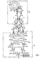
- the first optical Coupler 11 is optically connected to light source 10 and divides light L of light source 10 into two light signals L1 ' and L2 '.
- the second optical coupler 12 couples this from the sensor device 3 applied end of the second transmission path 7 of the series circuit 30 with the first optical Coupler 11 on the one hand and with a first photoelectric Converter 21 in the evaluation unit 20 on the other hand.
- the third optical coupler 13 couples this from the sensor device 3 opposite end of the first transmission link 4 the series circuit 30 with the first optical coupler 11 on the one hand and with a second photoelectric converter 22 on the other hand in the evaluation unit 20.
- the two light signals L1 'and L2' are thus from the first coupler 11 on opposite ends via the optical couplers 12 or 13 coupled into the optical series circuit 30.
- Both light signals L1 'and L2' pass through the optical series connection 30 now in opposite directions of passage. After transmission through the series connection 30 become the light signals designated L1 and L2 again decoupled from the series circuit 30 and via the respective optical coupler 13 or 12 of the evaluation unit 20 fed.
- the light intensities of the two light signals L1 ' and L2 'before being coupled into the series circuit 30 generally in a fixed relationship to each other set by the coupling ratios of the Coupler 11 to 13 can be predetermined.
- the light source 10 and the couplers 11, 12 and 13 form one Embodiment of means for sending the two opposing ones Light signals L1 'and L2' through the series circuit 30.
- Die Couplers 11, 12 and 13 can also at least partially through optical beam splitter to be replaced.
- the three couplers 11 to 13 and the two converters 21 and 22 can also alternate as transmitters and detectors operated light-emitting diodes can be provided with corresponding Electricity sources and evaluation electronics are connected. Pass through the two light signals L1 'and L2' the series circuit 30 then one after the other in time.
- the two optical transmission links 4 and 7 fiber optic formed and each include two optical fibers 41 and 43 or 71 and 73, which are connected via an optical connector 42 or 72 are separably connected.
- Such Plug connection 42 or 72 is advantageous to the one Current measurement in general at high voltage sensor device 3 to be able to separate from the evaluation unit 20.
- a commercially available fiber connector can be used as connector 42 or 72 according to the FC standard (OECA).
- the couplers 12 and 13 are now fiber couplers, each of which associated optical fiber 73 or 43 of the second or first Transmission path 7 or 4, each with two further optical fibers Pair 80 and 81 or 90 and 91.
- the coupler too 11 is now a fiber coupler, the two optical fibers 80 and 90 with a further optical fiber, not designated couples, which transmits the light L of the light source 10.
- the optical fiber 80 transmits the first light signal L1 ' coupling into the series circuit 30.
- the optical fiber 90 transmits the second light signal L2 'before coupling in the series circuit 30.
- the optical fiber 81 transmits this first light signal L1 after coupling out of the series connection 30.
- the optical fiber 91 finally transmits the second Light signal L2 after coupling out of the series circuit 30.
- the optical fibers 41, 42, 71, 72, 80, 81, 90 and 91 can their length can be adapted to site conditions.
- the Faraday sensor device 3 contains at least one material showing the magneto-optical Faraday effect. Under the influence of an alternating magnetic field H which at least partially penetrates the sensor device 3, the polarization of linearly polarized light passing through the sensor device 3 is rotated on account of the Faraday effect.
- the sensor device 3 can be designed in a manner known per se with one or more solid bodies, preferably made of glass, and in particular as shown as a solid glass ring with inner reflection surfaces deflecting the light signals L1 'and L2' or with at least one optical fiber.
- the sensor device 3 has two optical connections 3A and 3B in such a way that light coupled in at one connection 3A or 3B passes through the sensor device 3 and is coupled out again at the other connection 3B or 3A.
- the first connection 3A of the sensor device 3 is optically coupled to one end of the first optical transmission path 4 via the first polarizer 5 and preferably via a collimator lens 45.
- the second connection 3B of the sensor device 3 is optically coupled to one end of the second optical transmission path 7 via the second polarizer 6 and preferably via a further collimator lens 75.
- a positive angle value corresponds to the mathematically positive direction of rotation, that is to say the counterclockwise direction
- a negative angle value corresponds to the mathematically negative direction of rotation, that is to say clockwise, in relation to the direction of propagation of the light signal under consideration.
- the first light signal L1 'rotated in its plane of polarization by the Faraday measuring angle ⁇ is now fed to the second polarizer 6.
- the second polarizer 6 only lets through the portion of the incoming first light signal L1 'projected onto its polarization axis and thus has the function of a polarization analyzer for the first light signal L1'.
- the portion of the first light signal L1 'transmitted by the second polarizer 6 is fed to the first converter 21 as the first light signal L1 via the second transmission link 7 and the second coupler 12.
- the second light signal L2 ' is fed to the second polarizer 5 via the second transmission path 7 and is linearly polarized by the latter.
- the polarization plane of the linearly polarized second light signal L2 ' is rotated by a Faraday measuring angle - ⁇ which is dependent on the alternating magnetic field H and which, owing to the non-reciprocal property of the Faraday effect, has the same amount but the opposite sign as with the first light signal L1 '.
- the first polarizer 5 only lets through the portion of the incoming second light signal L2 'projected onto its polarization axis and thus acts as a polarization analyzer for the second light signal L2'.
- the portion of the second light signal L2 'transmitted by the first polarizer 5 is transmitted via the first transmission link 4 to the second converter 22 of the evaluation unit 20 as the second light signal designated L2.
- the polarization axes, transmission axis) of the two polarizers 5 and 6 are in all embodiments preferably at a polarizer angle ⁇ of an odd multiple of about 45 ° or about ⁇ / 4 set.
- the operating point lies with such a setting measurement at maximum sensitivity.
- the measuring arrangement shown is preferably provided for measuring an electrical alternating current I in at least one current conductor 2.
- the Faraday sensor device 3 detects the magnetic alternating field H generated inductively by this alternating current I and rotates the polarization planes of the two light signals L1 'and L2' by a measuring angle ⁇ or - ⁇ which is dependent on the alternating magnetic field H and thus on the alternating current I.
- the sensor device 3 in particular as a glass ring, surrounds the current conductor 2, so that both light signals L1 'and L2' circulate the alternating current I in a practically closed light path.
- the measuring angle ⁇ is directly proportional to the electrical alternating current I.
- the evaluation of the two light signals L1 and L2 in the evaluation unit 30 is preferably carried out as follows.
- the proportionality factors K1 and K2 of these conversions are determined by the photoelectric efficiencies and the subsequent amplifications of the signals in the converters 21 and 22 and can in particular also change over time.
- Each of the two intensity signals S1 and S2 is fed to an input of an associated first multiplier 23 or second multiplier 24 and an input of an associated first filter 28 or second filter 29 with a low-pass character.
- the DC signal component D1 of the first intensity signal S1 present at an output of the filter 28 is fed to a second input of the first multiplier 23.
- the DC signal component D2 of the second intensity signal S2 present at an output of the second filter 29 is fed to a second input of the second multiplier 24.
- Low-pass filters can be used as filters 28 and 29, for example, the cut-off frequencies of which are set below the lowest frequency in the spectrum of the alternating magnetic field H and the alternating electrical current I.
- the two DC signal components D1 and D2 and therefore also the two DC components I1 DC and I2 DC therefore do not contain any information about the alternating magnetic field H or the AC electrical current I, but do contain information about an undesirable DC drift (operating point drift) of the two light intensities I1 and I2 .
- This information about an intensity drift is now used for intensity normalization as follows.
- the first multiplier 23 forms the product D2 ⁇ S1 of the first intensity signal S1 and the DC signal component D2 of the second intensity signal S2.
- the second multiplier 24 forms the product D1 ⁇ S2 of the DC signal component D1 of the first intensity signal S1 and the second intensity signal S2.
- the sensitivities K1 and K2 of the two converters 21 and 22 fall when the measurement signal M is formed in accordance with equation (2) or the measurement signal M 'according to equation (3).
- the evaluation unit 20 contains a control circuit with a controller 33 and a controllable amplifier 31 as an actuator, which is controlled by the controller 33.
- the controllable amplifier 31 is either part of one of the two photoelectric converters or one of the two photoelectric converters connected downstream. In the exemplary embodiment shown, the controllable amplifier 31 is part of the first photoelectric converter 21 and is connected downstream of a photodiode as a photodetector for amplifying the signal of the photodiode.
- the amplitude of the first intensity signal S1 at the output of the converter 21 can thus be controlled by controlling the amplification factor of the controllable amplifier 31. This corresponds to a control of the proportionality factor (correction factor) K1, via which the intensity signal S1 is proportional to the light intensity I1.
- the second converter 22 also preferably contains a photodiode and a downstream amplifier with a fixed gain. The proportionality factor K2 of the second intensity signal S2 is therefore not changed.
- the evaluation unit again contains the two filters 28 and 29 for forming the direct signal components D1 and D2 of the two intensity signals S1 and S2, which are present at the outputs of the converters 21 and 22, and a subtractor connected to the outputs of the two filters 28 and 29 32 for forming the difference D1-D2 of the two DC signal components D1 and D2.
- This difference D1-D2 is fed to the controller 33 as a controlled variable.
- the controller 33 compares the controlled variable D1-D2 with a zero signal as the desired value and controls the gain of the controllable amplifier 31 until the control deviation between the controlled variable D1-D2 and the desired value 0 lies within a predetermined tolerance range.
- a subtractor 34 for forming the difference S1-S2 an adder 35 for forming the sum S1 + S2 and a divider 36 for forming the quotient signal from the differences S1-S2 and the sum S1 + S2 are for the formation of this measurement signal M ′′ provided as measurement signal M ′′ in the evaluation unit 20.
- the evaluation unit 20 can the measurement signal M according to Equation (2) or the measurement signal M 'according to equation (3) or the measurement signal M '' according to equation (6) with the help of a Value table and / or with the help of digital modules determine.
- the two electrical intensity signals S1 and S2 are then first of all using a.
- Analog / digital converter digitized and the digitized signals are from a microprocessor or a digital signal processor for processed the measurement signal M or M 'or M' '.
- the measurement signal M or M 'or M''determined according to one of equations (2) to (4) or equation (6) is practically completely normalized in terms of intensity. This means that undesired changes in the light intensities I1 and I2 of the two light signals L1 and L2 due to transmission losses due to attenuation, reflections or scattering in the series circuit 30 or due to vibrations or mechanical bends, in particular in the two transmission links 4 and 7, no longer occur affect the measurement signal M or M 'or M''. Scattering effects and reflections can occur in particular at the connections 3A and 3B of the sensor device 3 and at the plug connections 42 and 72.
- the complete intensity normalization of the measurement signal M or M 'or M'' can be seen if the intensity changes in the series circuit 30 are taken into account by additional transmission factors C1 and C2 in the light intensities I1 and I2.
- the generally time-dependent (real) transmission factor of an optical transmission link means the ratio of the light intensity of light arriving at one end of the transmission link to the input light intensity of the light when it is coupled into the other end of the transmission link.
- I1 B1 * C1 * I0 * cos 2nd ( ⁇ + ⁇ )
- I2 B2 ⁇ C2 ⁇ I0 ⁇ cos 2nd ( ⁇ - ⁇ )
- I0 is the light intensity of the light L of the light source 10.
- the cos 2 terms in equations (7) and (8) describe the dependence of the light intensity I1 and I2 on the Faraday measuring angle ⁇ for a given polarizer angle ⁇ .
- I1 DC B1C1I0 (cos 2nd ( ⁇ + ⁇ ))
- I2 DC B2 ⁇ C2 ⁇ I0 ⁇ (cos 2nd ( ⁇ - ⁇ )) DC
- optical fibers 41, 43, 71 and 73 because of their relatively high damping and vibration sensitivity are compensated in the measurement signal.
- transmission lines 4 and 7 can also use other optical fibers or free jet arrangements can be used.
- An additional problem when measuring an alternating magnetic field H or an alternating electrical current I in accordance with one of the measurement methods or one of the measurement arrangements described can be temperature influences in the sensor device 3. These temperature influences induce a linear birefringence ⁇ as a function ⁇ (T) of the temperature T in the sensor device 3, which can falsify the measurement of the magnetic alternating field H or the electrical alternating current I. Furthermore, temperature changes can also change the Verdet constant and thus the measuring sensitivity.
- the polarization axes of the two polarizers 5 and 6 are set at a polarizer angle ⁇ (not shown) to a natural axis (main axis, optical axis) of the linear birefringence ⁇ in the sensor device 3.
- a natural axis of the linear birefringence ⁇ is defined by the direction of polarization under which linearly polarized light coupled into the sensor device 3 leaves the sensor device 3 unchanged.
- linearly polarized light is coupled into the sensor device 3 with a polarization plane that is not parallel to one of the natural axes of the sensor device 3, the light is elliptically polarized as it passes through the sensor device 3 due to the linear birefringence ⁇ .
- the two natural axes of the linear birefringence ⁇ which are generally orthogonal to one another, can be determined in a manner known per se.
- the sensor device 3 can be arranged between a polarizer, for example the polarizer 5, and an analyzer, for example the polarizer 6.
- the polarization axes of the two polarizers are set perpendicular to each other.
- the two polarization axes of the polarizer and analyzer are now rotated in the same direction against a reference axis of the sensor device 3 until the intensity of the light transmitted by the analyzer is zero (maximum light extinction).
- the eigen axes are then parallel to the two polarization axes of the polarizer and analyzer.
- the two polarization axes can also be rotated in the same direction against the reference axis of the sensor device 3 until the intensity of the light transmitted by the analyzer is at a maximum (minimum light extinction). In this case, the light is circularly polarized when it exits the sensor device 3.
- the natural axes of the linear birefringence ⁇ are then offset by 45 ° or -45 ° to the polarization axis of the analyzer.
- Equation (11), (12) or (13) optimal polarizer angles ⁇ of the two polarizers 5 and 6 to the natural axis of the linear Birefringence ⁇ can be in a special embodiment just be set so that you are in a calibration measurement the measurement signal in its dependence on the temperature its expected setpoint without linear birefringence ⁇ for a given polarizer angle ⁇ as a parameter and changed the polarizer angle ⁇ until the current measurement signal M, M 'or M' 'with the practical temperature-independent setpoint.
- the bandwidth the measurement is carried out by the temperature compensation described above not reduced.
Landscapes
- Engineering & Computer Science (AREA)
- Power Engineering (AREA)
- Physics & Mathematics (AREA)
- General Physics & Mathematics (AREA)
- Condensed Matter Physics & Semiconductors (AREA)
- Measuring Magnetic Variables (AREA)
- Measuring Instrument Details And Bridges, And Automatic Balancing Devices (AREA)
Claims (12)
- Procédé pour mesurer un champ magnétique alternatif (H), dans lequela) deux signaux lumineux (L1, L2) passent en sens inverse dans un circuit série optique (30) composé d'une première voie de transmission optique (4), d'un premier polarisateur (5) d'un dispositif capteur (3) présentant l'effet Faraday, d'un deuxième polarisateur (6) et d'une deuxième voie de transmission optique (7),b) on convertit les intensités lumineuses (I1, I2) des deux signaux lumineux (L1, L2) après leur passage dans le circuit série optique (30) en signaux d'intensités électriques (SI, S2) proportionnels à ces intensités lumineuses (I1, I2),c) on forme à partir des deux signaux d'intensités électriques (S1, S2) à chaque fois une composante de signal continue (D1, D2) qui est proportionnelle à une composante de lumière continue (I1DC, I2DC) de l'intensité lumineuse (I1, I2) du signal lumineux respectif (L1, L2), les composantes de lumière continues (I1DC, I2DC) ne contenant aucune composante fréquentielle du champ magnétique alternatif (H), etd) on forme à partir des signaux d'intensités électriques (S1, S2) et de leurs composantes de signal continues (D1, D2) un signal de mesure (M, M'') pratiquement indépendant de variations d'intensité dans le circuit série optique (30) pour le champ magnétique alternatif (H).
- Procédé selon la revendication 1, dans lequel le signal de mesure (M) est proportionnel au quotient
- Procédé selon la revendication 1, dans lequela) on multiplie la composante continue (I1DC) de l'intensité lumineuse (I1) d'un premier signal lumineux (L1) par un facteur de correction et on adapte ce facteur de correction jusqu'à ce que la différence entre la composante continue (I1DC) multipliée par le facteur de correction et la composante continue (I2DC) de l'intensité lumineuse (I2) du deuxième signal lumineux (L2) se trouve à l'intérieur d'un domaine de tolérance prescrit autour de zéro,b) on forme un signal de mesure (M'') proportionnel au quotient formé à partir d'une différence de l'intensité lumineuse (I1), multipliée par ledit facteur de correction, du premier signal lumineux (L1) et de l'intensité lumineuse (12) du deuxième signal lumineux (L2) et à partir de la somme de l'intensité lumineuse (I1), multipliée par ledit facteur de correction, du premier signal lumineux (L1) et de l'intensité lumineuse (I2) du deuxième signal lumineux (L2).
- Procédé selon l'une des revendications 1 à 3, dans lequel les axes de polarisation des deux polarisateurs (5, 6) sont tournés l'un par rapport à l'autre d'un angle (a) égal au moins approximativement à ± 45°.
- Procédé selon l'une des revendications précédentes, dans lequel on mesure le champ magnétique alternatif (H) d'un courant électrique alternatif (I) et on exploite le signal de mesure (M, M'') comme mesure pour le courant électrique alternatif (I).
- Dispositif pour mesurer un champ magnétique alternatif (H), comportanta) un circuit série optique (30) composé d'une première voie de transmission optique (4), d'un premier polarisateur (5) d'un dispositif capteur (3) présentant l'effet Faraday, d'un deuxième polarisateur (6) et d'une deuxième voie de transmission optique (7),b) des moyens (10, 11, 12, 13) pour l'émission, en sens inverse, de deux signaux lumineux (L1, L2) à travers le circuit série optique (30),c) des moyens (21, 22) pour la conversion d'intensités lumineuses (I1, I2) des deux signaux lumineux (L1, L2) après leur passage dans le circuit série optique (30) en des signaux d'intensités électriques (S1, S2) proportionnels à ces intensités lumineuses (I1, I2),d) des moyens (28, 29) pour la formation à chaque fois d'une composante de signal continue (D1, D2) à partir des deux signaux d'intensités électriques (S1, S2), la composante de signal continue respective (D1, D2) étant proportionnelle à une composante de lumière continue (I1DC, I2DC) de l'intensité lumineuse (I1, I2) du signal lumineux (L1, L2) respectif et les composantes de lumière continues (I1DC, I2DC) ne contenant aucune composante fréquentielle du champ magnétique alternatif (H), ete) des moyens (23, 24, 25, 26, 27, 31, 32, 33, 34, 35, 36) pour la formation d'un signal de mesure (M, M'') pratiquement indépendant des variations d'intensité dans le circuit série optique (30) pour le champ magnétique alternatif (H) à partir des signaux d'intensités électriques (S1, S2) et de leurs composantes de signal continues (D1, D2).
- Dispositif selon la revendication 6, dans lequel le signal de mesure (M) est proportionnel au quotient (I2DC · I1 - I1DC · I2) / (I2DC · I1 + I1DC · I2) Il étant l'intensité lumineuse d'un premier signal (L1) parmi les deux signaux lumineux, I1DC étant sa composante continue, I2 étant l'intensité lumineuse d'un deuxième signal (L2) parmi les deux signaux lumineux et I2DC étant sa composante continue.
- Dispositif selon la revendication 6, dans lequel l'unité d'évaluation (20) comportea) un régulateur (33) pour réguler sur la valeur de consigne zéro, par réglage du facteur de correction, la différence entre la composante continue (I1DC), multipliée par un facteur de correction, de l'intensité lumineuse (Il) d'un premier signal lumineux (L1) et la composante continue (I2DC) de l'intensité lumineuse (I2) du deuxième signal lumineux (L2) et, de plus,b) des moyens (34, 35, 36) pour la formation d'un signal de mesure (M'') proportionnel au quotient formé à partir d'une différence de l'intensité lumineuse (I1), multipliée par ledit facteur de correction, du premier signal lumineux (L1) et de l'intensité lumineuse (I2) du deuxième signal lumineux (L2) et à partir de la somme de l'intensité lumineuse (I1), multipliée par ledit facteur de correction, du premier signal lumineux (L1) et de l'intensité lumineuse (I2) du deuxième signal lumineux (L2).
- Dispositif selon l'une des revendications 6 à 8, dans lequel les axes de polarisation des deux polarisateurs (5, 6) font l'un par rapport à l'autre un angle (α) égal au moins approximativement à ± 45°.
- Dispositif selon l'une des revendications 6 à 9, dans lequel le dispositif capteur (3) est agencé dans le champ magnétique alternatif (H) d'un courant électrique alternatif (I) et dans lequel les moyens d'évaluation (20) déduisent le signal de mesure (M) comme mesure pour le courant électrique alternatif (I).
- Dispositif selon l'une des revendications 6 à 10, dans lequel les deux voies de transmission optiques (4, 7) du circuit série (30) comprennent des fibres optiques.
- Dispositif selon la revendication 11, dans lequel les deux voies de transmission optiques (4, 7) du circuit série (30) comprennent chacune au moins deux fibres optiques (41, 43 et 71, 73) et une connexion à fiche optique (42 et 72) pour la connexion amovible des deux fibres optiques (41, 43 et 71, 73).
Applications Claiming Priority (3)
| Application Number | Priority Date | Filing Date | Title |
|---|---|---|---|
| DE19545759 | 1995-12-07 | ||
| DE19545759A DE19545759A1 (de) | 1995-12-07 | 1995-12-07 | Optisches Meßverfahren und optische Meßvorrichtung zum Messen eines magnetischen Wechselfeldes mit Intensitätsnormierung |
| PCT/DE1996/002248 WO1997021108A2 (fr) | 1995-12-07 | 1996-11-22 | Procede et dispositif de mesure optique pour mesurer un champ alternatif magnetique avec normalisation d'intensite |
Publications (2)
| Publication Number | Publication Date |
|---|---|
| EP0865610A2 EP0865610A2 (fr) | 1998-09-23 |
| EP0865610B1 true EP0865610B1 (fr) | 2000-03-08 |
Family
ID=7779511
Family Applications (1)
| Application Number | Title | Priority Date | Filing Date |
|---|---|---|---|
| EP96945748A Expired - Lifetime EP0865610B1 (fr) | 1995-12-07 | 1996-11-22 | Procede et dispositif de mesure optique pour mesurer un champ alternatif magnetique avec normalisation d'intensite |
Country Status (6)
| Country | Link |
|---|---|
| US (1) | US6154022A (fr) |
| EP (1) | EP0865610B1 (fr) |
| JP (1) | JP2000501187A (fr) |
| CA (1) | CA2239860A1 (fr) |
| DE (2) | DE19545759A1 (fr) |
| WO (1) | WO1997021108A2 (fr) |
Cited By (1)
| Publication number | Priority date | Publication date | Assignee | Title |
|---|---|---|---|---|
| US10317433B2 (en) | 2015-01-16 | 2019-06-11 | Siemens Aktiengesellschaft | Optoelectric measuring device and method for measuring an electrical current |
Families Citing this family (11)
| Publication number | Priority date | Publication date | Assignee | Title |
|---|---|---|---|---|
| WO1999008120A1 (fr) * | 1997-08-12 | 1999-02-18 | Siemens Aktiengesellschaft | Procede pour mesurer un champ magnetique et installation pour la mise en oeuvre dudit procede |
| WO2000037949A1 (fr) * | 1998-12-22 | 2000-06-29 | Siemens Aktiengesellschaft | Procede et dispositif de mesure optique d'un courant electrique a l'aide de signaux lumineux ayant differentes longueurs d'onde |
| US7786719B2 (en) * | 2005-03-08 | 2010-08-31 | The Tokyo Electric Power Company, Incorporated | Optical sensor, optical current sensor and optical voltage sensor |
| WO2006095619A1 (fr) * | 2005-03-08 | 2006-09-14 | The Tokyo Electric Power Company, Incorporated | Photocapteur de type à modulation d’intensité et capteur de tension/photocourant |
| WO2008073391A2 (fr) * | 2006-12-12 | 2008-06-19 | Abb Technology Ag | Détecteur multiplexé par répartition dans le temps pour un transducteur de courant magnéto-optique |
| CN103823106A (zh) * | 2012-08-29 | 2014-05-28 | 北京恒信创光电技术有限公司 | 光学电流互感器 |
| CN103443639B (zh) * | 2012-08-29 | 2015-08-05 | 北京恒信创光电技术有限公司 | 电流测量系统、光学电流互感器和固定装置、以及光信号采样器及其方法 |
| CN103809043B (zh) * | 2012-11-08 | 2016-06-08 | 南京南瑞继保电气有限公司 | 一种电弧光故障的检测判别方法 |
| US10197603B2 (en) * | 2015-04-01 | 2019-02-05 | General Electric Company | Optical current transducer with offset cancellation and current linearization |
| US10473697B2 (en) * | 2015-04-01 | 2019-11-12 | General Electric Company | Current transducer with offset cancellation |
| FR3110000B1 (fr) * | 2020-05-06 | 2022-05-27 | Commissariat Energie Atomique | Capteur de courant basé sur l’effet Faraday dans un gaz atomique |
Family Cites Families (7)
| Publication number | Priority date | Publication date | Assignee | Title |
|---|---|---|---|---|
| US4916387A (en) * | 1988-10-21 | 1990-04-10 | Asea Brown Boveri, Inc. | Optical system for a Faraday effect current sensor |
| GB9100924D0 (en) * | 1991-01-16 | 1991-02-27 | Rogers Alan J | Interference-free optical-fibre current measurement |
| AU643913B2 (en) * | 1992-02-21 | 1993-11-25 | Ngk Insulators, Ltd. | Optical magnetic field sensor |
| US5844409A (en) * | 1993-10-01 | 1998-12-01 | Siemens Aktiengesellschaft | Method and system for measuring an electric current with two light signals propagating in opposite directions, using the Faraday effect |
| DE4443948A1 (de) * | 1994-12-09 | 1996-06-13 | Siemens Ag | Verfahren und Anordnung zum Messen eines Magnetfeldes mit zwei gegenläufigen Lichtsignalen unter Ausnutzung des Faraday-Effekts mit Kompensation von Intensitätsänderungen |
| DE4446425A1 (de) * | 1994-12-23 | 1996-06-27 | Siemens Ag | Verfahren und Anordnung zum Messen eines Magnetfeldes unter Ausnutzung des Faraday-Effekts mit Kompensation von Intensitätsänderungen und Temperatureinflüssen |
| DE19506169A1 (de) * | 1995-02-22 | 1996-08-29 | Siemens Ag | Verfahren und Anordnung zum Messen eines Magnetfeldes unter Ausnutzung des Faraday-Effekts mit Kompensation von Intensitätsänderungen |
-
1995
- 1995-12-07 DE DE19545759A patent/DE19545759A1/de not_active Withdrawn
-
1996
- 1996-11-22 US US09/077,762 patent/US6154022A/en not_active Expired - Fee Related
- 1996-11-22 WO PCT/DE1996/002248 patent/WO1997021108A2/fr not_active Ceased
- 1996-11-22 DE DE59604623T patent/DE59604623D1/de not_active Expired - Fee Related
- 1996-11-22 CA CA002239860A patent/CA2239860A1/fr not_active Abandoned
- 1996-11-22 EP EP96945748A patent/EP0865610B1/fr not_active Expired - Lifetime
- 1996-11-22 JP JP9520858A patent/JP2000501187A/ja active Pending
Cited By (1)
| Publication number | Priority date | Publication date | Assignee | Title |
|---|---|---|---|---|
| US10317433B2 (en) | 2015-01-16 | 2019-06-11 | Siemens Aktiengesellschaft | Optoelectric measuring device and method for measuring an electrical current |
Also Published As
| Publication number | Publication date |
|---|---|
| DE59604623D1 (de) | 2000-04-13 |
| WO1997021108A2 (fr) | 1997-06-12 |
| CA2239860A1 (fr) | 1997-06-12 |
| US6154022A (en) | 2000-11-28 |
| DE19545759A1 (de) | 1997-06-12 |
| JP2000501187A (ja) | 2000-02-02 |
| WO1997021108A3 (fr) | 1997-08-14 |
| EP0865610A2 (fr) | 1998-09-23 |
Similar Documents
| Publication | Publication Date | Title |
|---|---|---|
| EP0799426B1 (fr) | Procede et dispositif pour mesurer un champ magnetique a l'aide de l'effet faraday avec compensation des variations d'intensite et des effets de la temperature | |
| EP0706662B1 (fr) | Procede optique permettant de mesurer un courant alternatif electrique compense en temperature et dispositif de mise en oeuvre du dit procede | |
| EP0721589B1 (fr) | Procede et dispositif permettant de mesurer une grandeur electrique alternative avec compensation de temperature | |
| EP0865610B1 (fr) | Procede et dispositif de mesure optique pour mesurer un champ alternatif magnetique avec normalisation d'intensite | |
| EP0779988B1 (fr) | Procede et dispositif permettant de mesurer un courant alternatif electrique avec compensation thermique | |
| EP0721590B1 (fr) | Procede et systeme permettant de mesurer un courant electrique au moyen de deux signaux lumineux opposes, a l'aide de l'effet faraday | |
| WO1994024572A1 (fr) | Procede optique permettant de mesurer un courant alternatif electrique compense en temperature et dispositif de mise en ×uvre dudit procede | |
| EP0866974B1 (fr) | Procede et dispositif de mesure optique pour mesurer une grandeur alternative avec mise a l'echelle de l'intensite | |
| DE19601727C1 (de) | Optisches Meßverfahren und optische Meßanordnung zum Messen eines magnetischen Wechselfeldes mit erweitertem Meßbereich und guter Linearität | |
| EP0786091B1 (fr) | Procede et dispositif permettant de mesurer une grandeur alternative electrique a compensation thermique | |
| EP0811170B1 (fr) | Procede et dispositif de mesure de champs magnetiques par effet de faraday avec compensation de variations d'intensite | |
| DE60118662T2 (de) | Anordnung zum Messen des elektrischen Stromes durch den Faraday-Effekt | |
| DE19517128A1 (de) | Verfahren und Anordnung zum Messen eines magnetischen Wechselfeldes mit Off-set-Faraday-Rotation zur Temperaturkompensation | |
| DE19544778A1 (de) | Verfahren und Anordnung zum Messen einer Meßgröße, insbesondere eines elektrischen Stromes, mit hoher Meßauflösung | |
| EP0904550B1 (fr) | Procede d'etalonnage thermique d'un dispositif optique de mesure des champs magnetiques et dispositif de mesure etalonne selon ce procede | |
| EP0786092B1 (fr) | Procede et dispositif de mesure optiques pour mesurer une tension alternative electrique ou un champ alternatif electrique avec compensation thermique | |
| DE69709385T2 (de) | Apparat mit rückführendem optischen kreis für die messung von physikalischen grössen mit hoher unterdrückung von umgebungsrauschen | |
| WO1999041617A1 (fr) | Procede et dispositif pour mesurer un champ magnetique par effet faraday | |
| WO1996018113A1 (fr) | Procede et dispositif de mesure d'un champ magnetique au moyen de deux signaux lumineux opposes, utilisant l'effet de faraday et compensant des changements d'intensite | |
| EP1277082A1 (fr) | Dispositif de conversion d'une lumiere de polarisation p e? en lumiere de polarisation predeterminee p a? | |
| DE19717496C1 (de) | Verfahren und Vorrichtung zur magnetooptischen Strommessung | |
| WO2024261224A1 (fr) | Système de mesure de courant à base optique et son utilisation |
Legal Events
| Date | Code | Title | Description |
|---|---|---|---|
| PUAI | Public reference made under article 153(3) epc to a published international application that has entered the european phase |
Free format text: ORIGINAL CODE: 0009012 |
|
| 17P | Request for examination filed |
Effective date: 19980519 |
|
| AK | Designated contracting states |
Kind code of ref document: A2 Designated state(s): CH DE FR GB IT LI |
|
| GRAG | Despatch of communication of intention to grant |
Free format text: ORIGINAL CODE: EPIDOS AGRA |
|
| GRAG | Despatch of communication of intention to grant |
Free format text: ORIGINAL CODE: EPIDOS AGRA |
|
| GRAH | Despatch of communication of intention to grant a patent |
Free format text: ORIGINAL CODE: EPIDOS IGRA |
|
| 17Q | First examination report despatched |
Effective date: 19990726 |
|
| GRAH | Despatch of communication of intention to grant a patent |
Free format text: ORIGINAL CODE: EPIDOS IGRA |
|
| GRAA | (expected) grant |
Free format text: ORIGINAL CODE: 0009210 |
|
| AK | Designated contracting states |
Kind code of ref document: B1 Designated state(s): CH DE FR GB IT LI |
|
| REG | Reference to a national code |
Ref country code: CH Ref legal event code: NV Representative=s name: SIEMENS SCHWEIZ AG Ref country code: CH Ref legal event code: EP |
|
| REF | Corresponds to: |
Ref document number: 59604623 Country of ref document: DE Date of ref document: 20000413 |
|
| ITF | It: translation for a ep patent filed | ||
| GBT | Gb: translation of ep patent filed (gb section 77(6)(a)/1977) |
Effective date: 20000511 |
|
| ET | Fr: translation filed | ||
| PG25 | Lapsed in a contracting state [announced via postgrant information from national office to epo] |
Ref country code: LI Free format text: LAPSE BECAUSE OF NON-PAYMENT OF DUE FEES Effective date: 20001130 Ref country code: CH Free format text: LAPSE BECAUSE OF NON-PAYMENT OF DUE FEES Effective date: 20001130 |
|
| PLBE | No opposition filed within time limit |
Free format text: ORIGINAL CODE: 0009261 |
|
| STAA | Information on the status of an ep patent application or granted ep patent |
Free format text: STATUS: NO OPPOSITION FILED WITHIN TIME LIMIT |
|
| 26N | No opposition filed | ||
| REG | Reference to a national code |
Ref country code: CH Ref legal event code: PL |
|
| PGFP | Annual fee paid to national office [announced via postgrant information from national office to epo] |
Ref country code: GB Payment date: 20011112 Year of fee payment: 6 |
|
| PGFP | Annual fee paid to national office [announced via postgrant information from national office to epo] |
Ref country code: FR Payment date: 20011123 Year of fee payment: 6 |
|
| REG | Reference to a national code |
Ref country code: GB Ref legal event code: IF02 |
|
| PGFP | Annual fee paid to national office [announced via postgrant information from national office to epo] |
Ref country code: DE Payment date: 20020121 Year of fee payment: 6 |
|
| PG25 | Lapsed in a contracting state [announced via postgrant information from national office to epo] |
Ref country code: GB Free format text: LAPSE BECAUSE OF NON-PAYMENT OF DUE FEES Effective date: 20021122 |
|
| PG25 | Lapsed in a contracting state [announced via postgrant information from national office to epo] |
Ref country code: DE Free format text: LAPSE BECAUSE OF NON-PAYMENT OF DUE FEES Effective date: 20030603 |
|
| GBPC | Gb: european patent ceased through non-payment of renewal fee | ||
| PG25 | Lapsed in a contracting state [announced via postgrant information from national office to epo] |
Ref country code: FR Free format text: LAPSE BECAUSE OF NON-PAYMENT OF DUE FEES Effective date: 20030731 |
|
| REG | Reference to a national code |
Ref country code: FR Ref legal event code: ST |
|
| PG25 | Lapsed in a contracting state [announced via postgrant information from national office to epo] |
Ref country code: IT Free format text: LAPSE BECAUSE OF NON-PAYMENT OF DUE FEES;WARNING: LAPSES OF ITALIAN PATENTS WITH EFFECTIVE DATE BEFORE 2007 MAY HAVE OCCURRED AT ANY TIME BEFORE 2007. THE CORRECT EFFECTIVE DATE MAY BE DIFFERENT FROM THE ONE RECORDED. Effective date: 20051122 |