EP0865721A2 - Rotobaler for agricultural crop - Google Patents
Rotobaler for agricultural crop Download PDFInfo
- Publication number
- EP0865721A2 EP0865721A2 EP97122006A EP97122006A EP0865721A2 EP 0865721 A2 EP0865721 A2 EP 0865721A2 EP 97122006 A EP97122006 A EP 97122006A EP 97122006 A EP97122006 A EP 97122006A EP 0865721 A2 EP0865721 A2 EP 0865721A2
- Authority
- EP
- European Patent Office
- Prior art keywords
- roll
- baler according
- roll baler
- loading device
- web
- Prior art date
- Legal status (The legal status is an assumption and is not a legal conclusion. Google has not performed a legal analysis and makes no representation as to the accuracy of the status listed.)
- Granted
Links
Images

Classifications
-
- A—HUMAN NECESSITIES
- A01—AGRICULTURE; FORESTRY; ANIMAL HUSBANDRY; HUNTING; TRAPPING; FISHING
- A01F—PROCESSING OF HARVESTED PRODUCE; HAY OR STRAW PRESSES; DEVICES FOR STORING AGRICULTURAL OR HORTICULTURAL PRODUCE
- A01F15/00—Baling presses for straw, hay or the like
- A01F15/07—Rotobalers, i.e. machines for forming cylindrical bales by winding and pressing
- A01F15/071—Wrapping devices
- A01F15/0715—Wrapping the bale in the press chamber before opening said chamber
Definitions
- the invention relates to a roller baler for agricultural crop with the actual Press space circumferentially delimiting winding elements that have an inlet for the feed release from a jacket sheet for fixing the shape of a finished bale, the jacket sheet is wound into a roll, which in a, outside of the actual press room the rolling station connected to the roll baler is mounted.
- Such unwinding stations are known as a shell-shaped, open housing, from which the jacket sheets of the wrapping material be deducted from a freely inserted roll or as facilities where the rolls of the wrapping material are rotatably held at their ends in a device.
- the invention proposes the unwind station in the area of a press wall a loading device for receiving a roll of material and to transfer the same to the unwind station.
- the loading device is configured from a lockable rest position into a transfer position swiveling.
- the actual one Press chamber 2 on the circumference of driven and optionally surface-structured Winding rollers 3 is limited.
- belts or a combination can also be used bound the press chamber 2 by belts and rollers.
- a guide 4 is provided, through which a jacket web 5 can be inserted through the inlet gap into the baling chamber 2 to a completely wound to enclose the roll bales in a form-fixing manner.
- the jacket web 5 is in a roll-off station AS withdrawn from a supply roll 6, which is mounted, for example, in a housing 7 in such a way that its axis of rotation runs parallel to the axis of rotation of the press chamber 2.
- a vertical axis 9 is fixedly connected to the side wall 8 of the press 1, around which an upper arm 10 and a lower arm 11 are rotatably mounted.
- the upper arm 10 is much shorter than the lower arm 11, so that with her firmly connected channel 12 occupies a position inclined to the horizontal.
- the gutter 12 is closed at its lower end by a wall 13 on which there is one in the channel 12 stored jacket roll 14 supports, which in the example shown ( Figure 1) as a further supply roll can be carried to role 6.
- FIGS. 3 and 4 An even more user-friendly embodiment is shown in FIGS. 3 and 4.
- the axis 9 ' is rotatable in supports 18 and 12 which are firmly connected to the side wall 8 19 mounted, the arm 11 'being firmly connected to the axis 9' in the lower region.
- a support 31 is arranged on the end of the arm 11 'remote from the axis 9' supports a gutter 12 '.
- This channel is in its position by means of a lock 32 with the support 31st connectable.
- the channel also has a support wall 13 'The other The end of the groove 12 'is gripped by a fork 20, the leg of which runs freely are connected to the channel 12 'via axle bolts 21 and 22.
- the fork 20 itself is fixed with the upper end portion of the axis 9 'connected.
- the gutter 12 'from the full lines to pivot into the position shown in dash-dotted lines is one Piston-cylinder unit 23 is provided, the cylinder with the axis 9 'and the piston rod is connected to the channel 12 '.
- this is provided with a guide surface 30.
- the channel 14 'as well as the channel 14 can also be pivoted through 90 °, so that it lies against the side of the baler 1.
- a protective flap 28 Fig. 2.
- the channel according to the invention is not only provided for the purpose of storing and storing a replacement roll, rather, it can also take up several rolls of winding yarn, if a finished one Bales should be fixed with twine instead of with a cover sheet. It’s even conceivable that a skein of thread is drawn off directly from a winding thread spool located in the trough is and then gets into the baling room via appropriate guides.
- the loading device LA is fastened in the region of a press side wall 8 shown.
- the person skilled in the art has no difficulty in determining the subject matter of the invention to modify so that the loading device LA also on an end or rear wall a roller baler according to the invention can be fastened in a functional manner.
Landscapes
- Life Sciences & Earth Sciences (AREA)
- Environmental Sciences (AREA)
- Storage Of Harvested Produce (AREA)
- Pretreatment Of Seeds And Plants (AREA)
Abstract
Die vorliegende Erfindung betrifft eine Rollballenpresse für landwirtschaftliches Erntegut mit
einem Gehäuse zur Aufnahme einer Materialrolle. Von dieser Materialrolle wird eine Mantelbahn
zur Formfixierung eines fertigen Ballens abgezogen. Um die Materialrolle betriebsgerecht
ohne großen Kraftaufwand an der Erntemaschine anzubringen ist im Bereich einer Seitenwand
der Ballenpresse eine schwenkbare Ladeeinrichtung zur Überführung einer Materialrolle
in eine Abrollstation vorgesehen. Diese Ladeeinrichtung kann aus einer Ruheposition in
eine Übergabeposition derart verschwenkt werden, daß die Materialrolle mit nur geringer
Kraft aus der Ladeeinrichtung in die Abrollstation geschoben werden kann.
Description
Die Erfindung betrifft eine Rollballenpresse für landwirtschaftliches Erntegut mit den eigentlichen Preßraum umfangsseitig begrenzenden Wickelelementen, die einen Einlaß für die Zufuhr von einer Mantelbahn zur Formfixierung eines fertigen Ballens freilassen, wobei die Mantelbahn zu einer Rolle aufgewickelt ist, die in einer, außerhalb des eigentlichen Preßraumes mit der Rollballenpresse verbundenen Abrollstation gelagert ist. Derartige Abrollstationen sind bekannt als schalenförmige, offene Gehäuse, aus denen die Mantelbahnen des Umhüllmaterials von einer frei eingelegten Rolle abgezogen werden oder als Einrichtungen, bei der die Rollen des Umhüllmaterials in einer Vorrichtung an ihren Enden drehbar gehalten werden.The invention relates to a roller baler for agricultural crop with the actual Press space circumferentially delimiting winding elements that have an inlet for the feed release from a jacket sheet for fixing the shape of a finished bale, the jacket sheet is wound into a roll, which in a, outside of the actual press room the rolling station connected to the roll baler is mounted. Such unwinding stations are known as a shell-shaped, open housing, from which the jacket sheets of the wrapping material be deducted from a freely inserted roll or as facilities where the rolls of the wrapping material are rotatably held at their ends in a device.
Das fachgerechte Einlegen der Bahnrollen erfolgt in allen Fällen von Hand, wobei die Maschine über Auftritte bestiegen werden muß. Je nach Lage der Abrollstation an der Presse ist der hierzu vom Fahrer aufzubringende Kraftaufwand erheblich, da Mantelbahnrollen ca. 40 kg schwer sind. Um derartige umständliche und kraftaufwendige Arbeiten zu vermeiden, die zudem mit einem erhöhten Unfallrisiko verbunden sind, wird erfindungsgemäß vorgeschlagen, der Abrollstation im Bereich einer Pressenwand eine Ladeeinrichtung zur Aufnahme einer Materialrolle und zur Übergabe derselben der Abrollstation zuzuordnen. In einer bevorzugten Ausgestaltung ist die Ladeeinrichtung von einer verriegelbaren Ruheposition in eine Übergabeposition schwenkbar.The correct insertion of the web rolls is done by hand in all cases, with the machine must be climbed over appearances. Depending on the position of the unwind station on the press, the This requires considerable effort from the driver, since the sheathing rolls are approx. 40 kg are heavy. In order to avoid such cumbersome and labor-intensive work, which also are associated with an increased risk of accidents, the invention proposes the unwind station in the area of a press wall a loading device for receiving a roll of material and to transfer the same to the unwind station. In a preferred one The loading device is configured from a lockable rest position into a transfer position swiveling.
Weitere vorteilhafte Ausführungsformen der Erfindung sind in den Unteransprüchen näher definiert. Further advantageous embodiments of the invention are detailed in the subclaims Are defined.
Im folgenden soll die Erfindung anhand eines Ausführungsbeispieles und mehrerer dieses schematisch darstellender Figuren näher erläutert werden. Dabei zeigt:
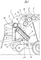
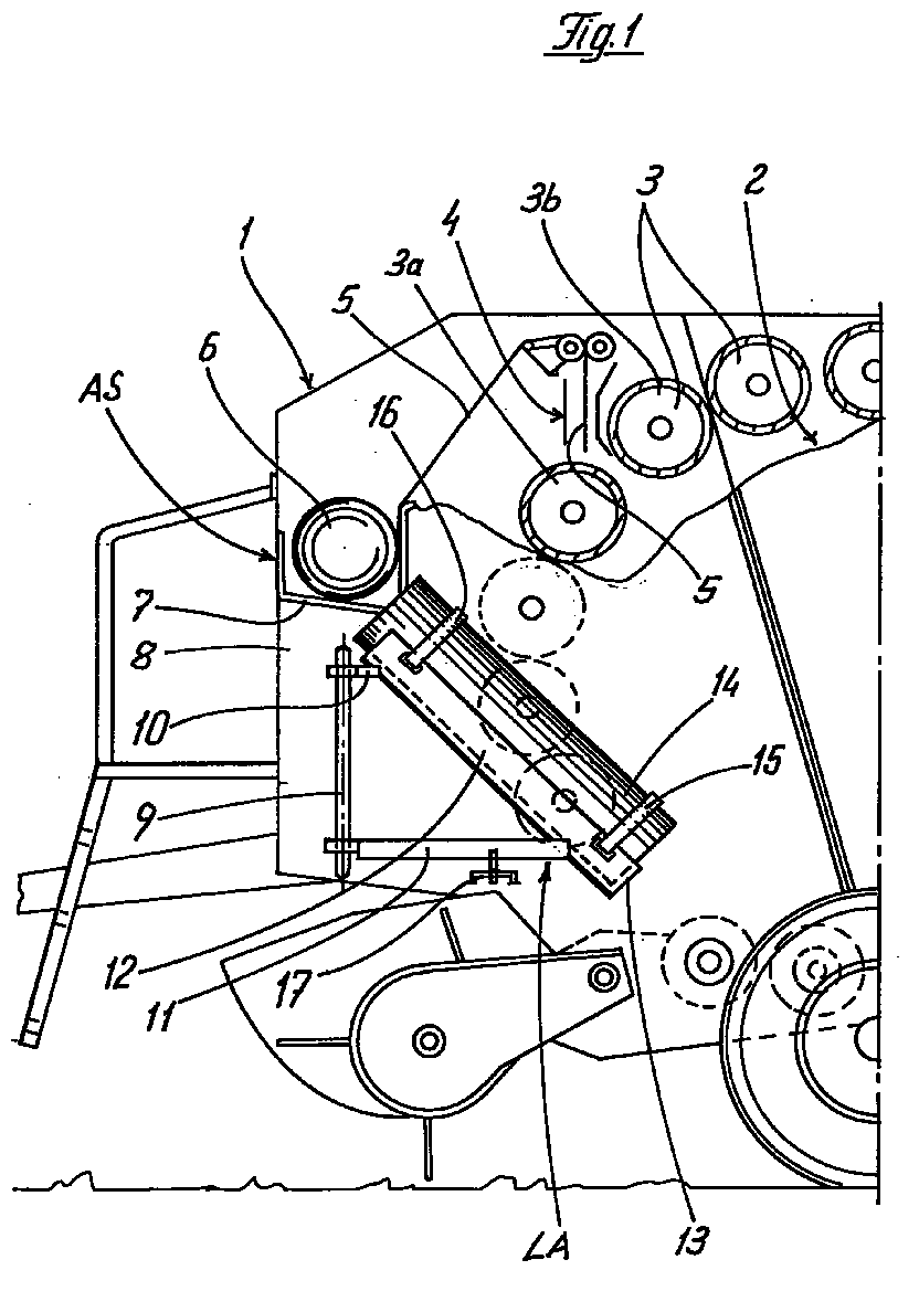
Figur 1- den vorderen Teil einer Ballenpresse in der Seitenansicht, teilweise im Schnitt,
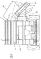
Figur 2- die in
Figur 1 dargestellte Presse in der Vorderansicht, Figur 3- einen Teil der in
Figur 2 dargestellten Ballenpresse in abgeänderter und vergrößerter Ausführungsform und Figur 4- den in
Figur 3 mit gestrichelten Linien dargestellten Teil vergrößert und um 90° verdreht.
- Figure 1
- the front part of a baler in side view, partly in section,
- Figure 2
- the press shown in Figure 1 in front view,
- Figure 3
- a part of the baler shown in Figure 2 in a modified and enlarged embodiment and
- Figure 4
- the part shown in Figure 3 with broken lines enlarged and rotated by 90 °.
Mit 1 ist der vordere Teil einer an sich bekannten Rollballenpresse bezeichnet, deren eigentlicher
Preßraum 2 umfangsseitig von angetriebenen und gegebenenfalls oberflächenstrukturierten
Wickelwalzen 3 begrenzt ist. Anstelle von Walzen können auch Riemen oder eine Kombination
von Riemen und Walzen den Preßraum 2 umgrenzen. Oberhalb der Wickelwalzen 3a
und 3b, die einen Einlaßspalt bilden, ist eine Führung 4 vorgesehen, durch welche eine Mantelbahn
5 durch den Einlaßspalt in den Preßraum 2 eingeführt werden kann, um einen fertig gewickelten
Rollballen formfixierend zu umschließen. Die Mantelbahn 5 wird in einer Abrollstation
AS von einer Vorratsrolle 6 abgezogen, die beispielsweise in einem Gehäuse 7 gelagert ist
und zwar derart, daß ihre Rotationsachse parallel zur Rotationsachse des Preßraumes 2 verläuft.
Mit der Seitenwand 8 der Presse 1 ist eine vertikal verlaufende Achse 9 fest verbunden,
um die ein oberer Arm 10 und ein unterer Arm 11 drehbar gelagert sind. Wie aus Figur 1 zu
erkennen, ist der obere Arm 10 wesentlich kürzer, als der untere Arm 11, so daß die mit ihr
fest verbundene Rinne 12 eine zur Horizontalen geneigt verlaufende Lage einnimmt. Die Rinne
12 ist an ihrem unteren Ende durch eine Wand 13 geschlossen, an der sich eine in der Rinne 12
abgelegte Mantelbahnrolle 14 abstützt, die im dargestellten Beispiel (Figur 1) als weitere Vorratsrolle
zur Rolle 6 mitgeführt werden kann. Letztere wird durch Bandagen 15 und 16 fixiert.
In der in Figur 1 dargestellten Lage ist der untere Arm 11 über einen Feststeller 17 in der Ruheposition
fixiert. Sobald die Rolle 6 aufgebraucht ist, wird der Feststeller 17 gelöst und die
Rinne 12 aus der in Figur 1 dargestellten Lage in die in Figur 2 dargestellte Lage verschwenkt.
In dieser Lage kann die Rinne ebenfalls auf nicht dargestellte Art und Weise verriegelt werden. With 1 the front part of a known roller baler is designated, the actual one
Nach Lösen der Bandagen 15 und 16 ist es dann dem Fahrer sehr leicht möglich, die Ersatzrolle
14 in das Gehäuse 7 einzuschieben.After releasing the
Eine noch bedienerfreundlichere Ausführungsform ist in den Figuren 3 und 4 dargestellt. In
diesem Fall ist die Achse 9' drehbar in mit der Seitenwand 8 fest verbundenen Stützen 18 und
19 gelagert, wobei mit der Achse 9' im unteren Bereich der Arm 11' fest verbunden ist. Mit
dem der Achse 9' entfernten Ende des Armes 11' ist eine Auflage 31 angeordnet, auf die sich
eine Rinne 12' abstützt. Diese Rinne ist in ihrer Lage mittels Feststeller 32 mit der Auflage 31
koppelbar. An ihrem unteren Ende weist die Rinne ebenfalls eine Stützwand 13' auf Das andere
Ende der Rinne 12' wird von einer Gabel 20 umgriffen, deren frei auslaufende Schenkel
über Achsbolzen 21 und 22 mit der Rinne 12' verbunden sind. Die Gabel 20 selbst ist fest mit
dem oberen Endbereich der Achse 9' verbunden. Um die Rinne 12' aus der mit vollen Linien
dargestellten Lage in die mit strichpunktierten Linien dargestellte zu verschwenken, ist eine
Kolbenzylindereinheit 23 vorgesehen, deren Zylinder mit der Achse 9' und deren Kolbenstange
mit der Rinne 12' verbunden ist. Wie im Falle der Ausführungsform nach Figur 1 wird auch
hier die Ersatzrolle 14' von Bandagen 15' und 16' während des Transportes und während des
Einsatzes auf dem Feld gehalten.An even more user-friendly embodiment is shown in FIGS. 3 and 4. In
In this case, the axis 9 'is rotatable in
Um die Übergabe der Ersatzrolle 14' aus der Rinne 12' in deren angehobener Position in das
Gehäuse 7' zu erleichtern, sind von außen her mit dem Rinnenboden und dem Gehäuseboden
Konsolen 24 und 25 verschweißt, in denen Rollen 26 und 27 drehbar gelagert sind. Diese Rollen
26 und 27 greifen durch im Boden des Gehäuses 7' und im Boden der Rinne 12' vorgesehene
Schlitze soweit hindurch, daß die Ersatzrolle 14' auf den Rollen aufruht. Während der
Übergabe von der Rinne 12' in das Gehäuse 7' rollt demzufolge die Ersatzrolle 14' auf den
Rollen 26 bzw. 27 ab, von denen der Einfachheit halber jeweils nur eine dargestellt ist.To transfer the replacement roll 14 'from the groove 12' in its raised position in the
To facilitate housing 7 'are from the outside with the channel bottom and the housing bottom
Welded
Um zu vermeiden, daß die Ersatzrolle 14' während der Übergabe vor die Gehäusewand 29
stößt, ist diese mit einer Leitfläche 30 versehen.In order to avoid that the replacement roller 14 'during the transfer in front of the
Selbstverständlich kann auch die Rinne 14' ebenso wie die Rinne 14 um 90° verschwenkt werden,
so daß sie seitlich an der Ballenpresse 1 anliegt. Im angeklappten Zustand - also in der
Ruheposition - werden die Rinnen von einer Schutzklappe 28 (Fig. 2) abgedeckt. Of course, the channel 14 'as well as the
Die erfindungsgemäße Rinne ist nicht nur zur Aufgabe und Speicherung einer Ersatzrolle vorgesehen, sie kann vielmehr auch mehrere Rollen von Wickelgarn aufnehmen, falls ein fertiger Ballen anstatt mit einer Mantelbahn mit Bindegarn formfixiert werden soll. Es ist sogar denkbar, daß ein Garnstrang direkt aus einer in der Rinne befindlichen Wickelgarnrolle abgezogen wird und dann über entsprechende Führungen in den Ballenpreßraum gelangt.The channel according to the invention is not only provided for the purpose of storing and storing a replacement roll, rather, it can also take up several rolls of winding yarn, if a finished one Bales should be fixed with twine instead of with a cover sheet. It’s even conceivable that a skein of thread is drawn off directly from a winding thread spool located in the trough is and then gets into the baling room via appropriate guides.
Im Ausführungsbeispiel ist eine Befestigung der Ladeeinrichtung LA im Bereich einer Pressenseitenwand
8 gezeigt. Dem Fachmann bereit es jedoch keine Schwierigkeiten, den Erfindungsgegenstand
so abzuwandeln, daß die Ladeeinrichtung LA auch an einer Stirn- oder Rückwand
einer Rollballenpresse erfindungsgemäß funktionstüchtig befestigbar ist. In the exemplary embodiment, the loading device LA is fastened in the region of a
- 11
- - Vorderer Teil- front part
- 22nd
- - Preßraum- press room
- 33rd
- - Wickelwalzen- winding rollers
- 3a3a
- - Wickelwalzen- winding rollers
- 3b3b
- - Wickelwalzen- winding rollers
- 44th
- - Führungen- Guides
- 55
- - Materialbahn- material web
- 66
- - Vorratsrolle- supply roll
- 77
- - Abrollstation, Gehäuse- Unwind station, housing
- 88th
- - Seitenwand- Side wall
- 99
- - Achse- axis
- 9'9 '
- - Achse- axis
- 1010th
- - oberer Arm- upper arm
- 1111
- - unterer Arm- lower arm
- 11'11 '
- - unterer Arm- lower arm
- 1212th
- - Rinne- gutter
- 12'12 '
- - Rinne- gutter
- 1313
- - Wand- wall
- 13'13 '
- - Wand- wall
- 1414
- - Mantelbahnrolle- roll of casing
- 14'14 '
- - Mantelbahnrolle- roll of casing
- 1515
- - Bandagen- bandages
- 15'15 '
- - Bandagen- bandages
- 1616
- - Bandagen- bandages
- 16'16 '
- - Bandage- bandage
- 1717th
- - Feststeller- lock
- 1818th
- - Stützen- Support
- 1919th
- - Stützen- Support
- 2020th
- - Gabel - Fork
- 2121
- - Achsbolzen- axle bolts
- 2222
- - Achsbolzen- axle bolts
- 2323
- - Kolbenzylindereinheit- piston-cylinder unit
- 2424th
- - Konsolen- consoles
- 2525th
- - Konsolen- consoles
- 2626
- - Rollen- Roll
- 2727
- - Rollen- Roll
- 2828
- - Schutzklappe- protective flap
- 2929
- - Gehausewand- Housing wall
- 3030th
- - Leitfläche- guide surface
- 3131
- - Auflage- edition
- 3232
- - Feststeller- lock
- ASAS
- - Abrollstation- unwind station
- LALA
- - Ladeeinrichtung- loading device
Claims (14)
dadurch gekennzeichnet,
daß der Abrollstation (AS, 7, 7') im Bereich einer Pressenwand (8) eine Ladeeinrichtung (LA) zur Aufnahme einer Bahnrolle (14, 14') und zur Übergabe der Bahnrolle an die Abrollstation (AS, 7, 7') zugeordnet ist.Roll baler for agricultural crops with the actual pressing space circumferentially delimiting winding elements that leave an inlet for the supply of a jacket web for fixing the shape of a finished bale, the jacket web being wound into a roll that is connected to a roll station connected to the roll baler outside the actual press room is stored.
characterized by
that the unwind station (AS, 7, 7 ') in the area of a press wall (8) is assigned a loading device (LA) for receiving a web roll (14, 14') and for transferring the web roll to the unwind station (AS, 7, 7 ') is.
dadurch gekennzeichnet,
daß die Ladeeinrichtung (LA) von einer verriegelbaren Ruheposition in eine Übergabeposition schwenkbar ist.Roll baler according to claim 1,
characterized by
that the loading device (LA) can be pivoted from a lockable rest position into a transfer position.
dadurch gekennzeichnet,
daß die Ladeeinrichtung (LA) um eine vertikale Achse (9, 9') schwenkbar ist.Roll baler according to claim 1 or 2,
characterized by
that the loading device (LA) can be pivoted about a vertical axis (9, 9 ').
dadurch gekennzeichnet,
daß die Ladeeinrichtung (LA) um eine horizontale Achse (21, 22) schwenkbar ist.Roll baler according to at least one of the preceding claims 1 to 3,
characterized by
that the loading device (LA) is pivotable about a horizontal axis (21, 22).
dadurch gekennzeichnet,
daß die Ladeeinrichtung (LA) in ihrer Ruheposition zur Horizontalen geneigt verläuft. Roll baler according to one or more of claims 1 to 4,
characterized by
that the loading device (LA) is inclined to the horizontal in its rest position.
dadurch gekennzeichnet,
daß die Ladeeinrichtung (LA) als Rinne (12, 12') ausgebildet ist, die an ihrem einen Ende eine Anlage (13, 13') für eine Stirnseite der Bahnrolle (14, 14') aufweist.Roll baler according to one or more of claims 1 to 5,
characterized by
that the loading device (LA) is designed as a trough (12, 12 ') which has at one end a system (13, 13') for an end face of the web roll (14, 14 ').
dadurch gekennzeichnet,
daß die Rinne (12) über einen oberen und einen unteren Arm (10, 11) drehbar an einer vertikalen mit der Pressenwand (8) verbundenen Achse (9) schwenkbar ist, wobei der untere Arm (11) der längere ist und mittels eines Feststellers (17) in Ruheposition arretierbar ist.Roll baler according to one or more of claims 1 to 6,
characterized by
that the trough (12) via an upper and a lower arm (10, 11) is rotatable on a vertical axis (9) connected to the press wall (8), the lower arm (11) being the longer one and by means of a lock (17) can be locked in the rest position.
dadurch gekennzeichnet,
daß der Rinne (12, 12') zumindest eine eine Bahnrolle (14, 14') fixierende Bandage(15, 16 bzw. 15', 16') zugeordnet ist.Roll baler according to one or more of claims 1 to 7,
characterized by
that the channel (12, 12 ') is assigned at least one bandage (15, 16 or 15', 16 ') which fixes a web roll (14, 14').
dadurch gekennzeichnet,
daß die Rinne (12, 12') in Ruheposition von einer klappbaren Seitenschutzverkleidung (30) abgedeckt ist.Roll baler according to one or more of claims 1 to 8,
characterized by
that the channel (12, 12 ') is covered in the rest position by a foldable side protection panel (30).
dadurch gekennzeichnet,
daß die Rinne (12') in ihrem oberen Bereich schwenkbar in einer Gabel (20) gehalten ist.Roll baler according to one or more of claims 1 to 9,
characterized by
that the groove (12 ') is pivotally held in a fork (20) in its upper region.
dadurch gekennzeichnet,
daß die Rinne (12') in ihrem unteren Bereich in einer Auflage (31) abgestützt ist. Roll baler according to claim 10,
characterized by
that the channel (12 ') is supported in its lower region in a support (31).
dadurch gekennzeichnet,
daß an der Rinne (12') eine Kolbenzylindereinheit (22) zum Schwenken derselben aus der zur Horizontalen geneigten Ruheposition in die etwa horizontale Übergabeposition für die Bahnrolle (14') angreift.Roll baler according to claims 10 or 11,
characterized by
that on the trough (12 ') a piston-cylinder unit (22) for pivoting the same from the rest position inclined to the horizontal engages in the approximately horizontal transfer position for the web roll (14').
dadurch gekennzeichnet,
daß die Auflage (31) gabelförmig ausgebildet und über einen Arm (11') an einer senkrecht verlaufenden Achse (9') befestigt ist.Roll baler according to one of claims 10 to 12,
characterized by
that the support (31) is fork-shaped and is attached via an arm (11 ') to a vertical axis (9').
dadurch gekennzeichnet,
daß sowohl der Boden des Gehäuses (7') als auch der Boden der Rinne (12') zumindest eine Durchbrechung aufweist, durch die zumindest je eine Stützrolle (26, 27) mit quer zur Längsachse der Rinne (12') verlaufender Drehachse bereichsweise hindurchgreift.Roll baler according to one or more of claims 1 to 13,
characterized by
that both the bottom of the housing (7 ') and the bottom of the trough (12') have at least one opening through which at least one support roller (26, 27) with areas of rotation extending transversely to the longitudinal axis of the trough (12 ') extends in regions .
Applications Claiming Priority (2)
| Application Number | Priority Date | Filing Date | Title |
|---|---|---|---|
| DE19711164A DE19711164A1 (en) | 1997-03-18 | 1997-03-18 | Roll baler for agricultural crops |
| DE19711164 | 1997-03-18 |
Publications (3)
| Publication Number | Publication Date |
|---|---|
| EP0865721A2 true EP0865721A2 (en) | 1998-09-23 |
| EP0865721A3 EP0865721A3 (en) | 2000-04-05 |
| EP0865721B1 EP0865721B1 (en) | 2005-01-26 |
Family
ID=7823725
Family Applications (1)
| Application Number | Title | Priority Date | Filing Date |
|---|---|---|---|
| EP97122006A Expired - Lifetime EP0865721B1 (en) | 1997-03-18 | 1997-12-13 | Rotobaler for agricultural crop |
Country Status (5)
| Country | Link |
|---|---|
| US (1) | US5996307A (en) |
| EP (1) | EP0865721B1 (en) |
| DE (2) | DE19711164A1 (en) |
| PL (1) | PL185534B1 (en) |
| UA (1) | UA71537C2 (en) |
Cited By (6)
| Publication number | Priority date | Publication date | Assignee | Title |
|---|---|---|---|---|
| DE102010027539B3 (en) * | 2010-07-16 | 2011-12-29 | Maschinenfabrik Bernard Krone Gmbh | baler |
| EP2517550A1 (en) * | 2011-04-28 | 2012-10-31 | CNH Belgium N.V. | Net roll support for storage and installation in baler |
| EP3384759A1 (en) * | 2017-04-07 | 2018-10-10 | Maschinenfabrik Bernard Krone GmbH & Co. KG | Agricultural large packing press |
| DE102017122130A1 (en) | 2017-09-25 | 2019-03-28 | Usines Claas France S.A.S. | Agricultural round baler and method for loading a feeder of a round baler |
| EP3590327A1 (en) * | 2018-07-05 | 2020-01-08 | CNH Industrial Belgium N.V. | A baler |
| EP3785521A1 (en) * | 2019-08-28 | 2021-03-03 | Maschinenfabrik Bernard Krone GmbH & Co. KG | Agricultural baler with a binding and method for maintaining the baler |
Families Citing this family (34)
| Publication number | Priority date | Publication date | Assignee | Title |
|---|---|---|---|---|
| DE10004564A1 (en) * | 2000-02-02 | 2001-08-09 | Lely Welger Maschinenfabrik Gm | Cylindrical baling machine has trolley for carrying roll of wrapping material which can be attached to mounting on the press fitted with guides and auxiliary drive which allows trolley to be loaded to position where roll can be fitted |
| DE10004563A1 (en) | 2000-02-02 | 2001-08-09 | Lely Welger Maschinenfabrik Gm | Roll baler for agricultural stalks |
| US6606843B1 (en) | 2000-03-21 | 2003-08-19 | Deere & Company | Structure for reliably feeding and spreading net wrap material, of a width greater than the width of a round baler chamber, so as to cover opposite end segments of a bale located in the chamber |
| DE10045843A1 (en) * | 2000-09-14 | 2002-03-28 | Thomas Schuster | Device for unwinding of net or film webs for wrapping bales has net or film roll installed in roll case with inclined bottom ramp which inclines progressively more as it nears its lowest point |
| DE10114577A1 (en) * | 2001-03-24 | 2002-09-26 | Deere & Co | Agricultural machine e.g. baler has reel holder with at least one horizontally extending support on which reel of wrapping material can be pushed |
| US6857251B2 (en) * | 2002-06-08 | 2005-02-22 | Cnh America Llc | Pivoting side twine box for round balers |
| US7162950B2 (en) | 2002-09-25 | 2007-01-16 | Cnh America Llc | Twine box for round balers |
| DE102004027308A1 (en) * | 2004-06-04 | 2005-12-29 | Welger Maschinenfabrik Gmbh | Round baler for agricultural stalks |
| DE102004027307A1 (en) * | 2004-06-04 | 2005-12-22 | Welger Maschinenfabrik Gmbh | Device for wrapping harvested bales |
| DE102005015225A1 (en) | 2005-04-02 | 2006-10-26 | Deere & Company, Moline | loader |
| US7430959B2 (en) * | 2006-11-23 | 2008-10-07 | Elgin Routledge | Device for lifting bale wrapping rolls |
| US8925287B2 (en) * | 2009-03-19 | 2015-01-06 | Deere & Company | Arrangement on baler for ergonomic loading of bale wrapping material rolls |
| NL1037002C2 (en) * | 2009-05-29 | 2010-11-30 | Lely Patent Nv | CENTER OF FOIL. |
| EP2335906A1 (en) * | 2009-12-21 | 2011-06-22 | Trioplast AB | Prestretched film |
| US9320199B2 (en) | 2011-11-22 | 2016-04-26 | Cnh Industrial America Llc | Multiple rolls net wrap assembly |
| DE102012002796A1 (en) * | 2012-02-15 | 2013-08-22 | Usines Claas France S.A.S. | baler |
| KR101419726B1 (en) * | 2013-01-21 | 2014-09-22 | 주식회사 아세아텍 | Wrapping device |
| US9603308B2 (en) | 2014-06-26 | 2017-03-28 | Cnh Industrial Canada, Ltd. | Continuous round baler with variable conveyor |
| US10827684B2 (en) | 2014-06-26 | 2020-11-10 | Cnh Industrial Canada, Ltd. | Mobile agricultural wrapping system and method |
| US9854744B2 (en) | 2014-12-11 | 2018-01-02 | Cnh Industrial America Llc | Adjusting bale density setting based on bale weight and/or moisture |
| US9622417B2 (en) | 2015-05-01 | 2017-04-18 | Cnh Industrial America Llc | Tailgate motion adjustment system |
| NL2014872B1 (en) * | 2015-05-28 | 2016-12-30 | Forage Innovations Bv | Wrapping device for wrapping a bale in a bale forming chamber. |
| US10161431B2 (en) | 2015-09-04 | 2018-12-25 | Cnh Industrial America Llc | Net pole latch mechanism |
| CA3026362A1 (en) * | 2017-12-04 | 2019-06-04 | Vermeer Manufacturing Company | Wrap material transfer device |
| US10934143B2 (en) * | 2018-07-13 | 2021-03-02 | Deere & Company | Net wrap lifting device |
| US10820527B2 (en) | 2018-07-13 | 2020-11-03 | Deere & Company | Baler with netwrap roll loading device |
| DE102019003769B4 (en) * | 2019-05-29 | 2021-09-09 | Maschinenfabrik Bernard Krone GmbH & Co. KG | Baler |
| GB201909536D0 (en) | 2019-07-02 | 2019-08-14 | Kuhn Geldrop Bv | Net/film roll support |
| EP3939413B1 (en) * | 2020-07-16 | 2024-09-11 | AGCO Corporation | Baling apparatus |
| GB202106326D0 (en) | 2021-05-04 | 2021-06-16 | Agco Int Gmbh | Baling apparatus |
| GB202113177D0 (en) | 2021-09-15 | 2021-10-27 | Agco Int Gmbh | Baling apparatus |
| US12232453B2 (en) * | 2022-05-18 | 2025-02-25 | Agco Corporation | Agricultural baler |
| US12477997B2 (en) * | 2023-10-31 | 2025-11-25 | Cnh Industrial Canada, Ltd. | Bale wrap assembly loading system for an agricultural harvester |
| CN120858755A (en) * | 2024-04-30 | 2025-10-31 | 凯斯纽荷兰工业美国有限责任公司 | Bale wrapper assembly management system for agricultural harvester |
Family Cites Families (11)
| Publication number | Priority date | Publication date | Assignee | Title |
|---|---|---|---|---|
| DE3227160C3 (en) * | 1982-07-21 | 1995-03-23 | Claas Ohg | Rolled bales from agricultural stalks |
| DE3429203A1 (en) * | 1984-08-08 | 1986-02-20 | Claas Ohg, 4834 Harsewinkel | ROLLING BALLS FROM AGRICULTURAL HARVEST |
| US4677807A (en) * | 1986-07-08 | 1987-07-07 | Deere & Company | System for automatically enveloping a large round bale with a wrapping |
| US4691503A (en) * | 1986-07-08 | 1987-09-08 | Deere & Company | Housing for holding a supply roll of large round bale wrap material |
| US4956959A (en) * | 1989-06-23 | 1990-09-18 | Deere & Company | Housing for holding a supply roll of large round bale wrap material |
| DE4037040C2 (en) * | 1989-12-02 | 1994-05-19 | Claas Ohg | Round baler for agricultural crops |
| DE3941727C3 (en) * | 1989-12-18 | 2003-02-20 | Rpp International Ltd | Device for packing garbage |
| US5181368A (en) * | 1991-12-17 | 1993-01-26 | Deere & Company | Housing for holding a supply roll of large round bale wrap material |
| DE9211541U1 (en) * | 1992-08-27 | 1992-11-05 | Maschinenfabriken Bernard Krone Gmbh, 4441 Spelle | Round baler for agricultural crops |
| DE4308646C2 (en) * | 1993-03-18 | 2000-01-27 | Claas Ohg | Crop round bale forming machine |
| US5433059A (en) * | 1993-04-27 | 1995-07-18 | Agco Corporation | Round bale wrapping |
-
1997
- 1997-03-18 DE DE19711164A patent/DE19711164A1/en not_active Withdrawn
- 1997-12-13 EP EP97122006A patent/EP0865721B1/en not_active Expired - Lifetime
- 1997-12-13 DE DE59712185T patent/DE59712185D1/en not_active Expired - Lifetime
-
1998
- 1998-01-16 PL PL98324326A patent/PL185534B1/en unknown
- 1998-03-12 US US09/041,559 patent/US5996307A/en not_active Expired - Lifetime
- 1998-03-17 UA UA98031356A patent/UA71537C2/en unknown
Cited By (10)
| Publication number | Priority date | Publication date | Assignee | Title |
|---|---|---|---|---|
| DE102010027539B3 (en) * | 2010-07-16 | 2011-12-29 | Maschinenfabrik Bernard Krone Gmbh | baler |
| EP2407024A3 (en) * | 2010-07-16 | 2013-10-16 | Maschinenfabrik Bernard Krone GmbH | Baling press |
| EP2517550A1 (en) * | 2011-04-28 | 2012-10-31 | CNH Belgium N.V. | Net roll support for storage and installation in baler |
| EP3384759A1 (en) * | 2017-04-07 | 2018-10-10 | Maschinenfabrik Bernard Krone GmbH & Co. KG | Agricultural large packing press |
| DE102017003447A1 (en) * | 2017-04-07 | 2018-10-11 | Maschinenfabrik Bernard Krone GmbH & Co. KG | Large agricultural pack press |
| DE102017122130A1 (en) | 2017-09-25 | 2019-03-28 | Usines Claas France S.A.S. | Agricultural round baler and method for loading a feeder of a round baler |
| EP3590327A1 (en) * | 2018-07-05 | 2020-01-08 | CNH Industrial Belgium N.V. | A baler |
| BE1026444B1 (en) * | 2018-07-05 | 2020-02-04 | Cnh Ind Belgium Nv | BALEN PRESS |
| US11116141B2 (en) | 2018-07-05 | 2021-09-14 | Cnh Industrial America Llc | Baler |
| EP3785521A1 (en) * | 2019-08-28 | 2021-03-03 | Maschinenfabrik Bernard Krone GmbH & Co. KG | Agricultural baler with a binding and method for maintaining the baler |
Also Published As
| Publication number | Publication date |
|---|---|
| EP0865721B1 (en) | 2005-01-26 |
| DE59712185D1 (en) | 2005-03-03 |
| PL185534B1 (en) | 2003-05-30 |
| US5996307A (en) | 1999-12-07 |
| UA71537C2 (en) | 2004-12-15 |
| DE19711164A1 (en) | 1998-09-24 |
| EP0865721A3 (en) | 2000-04-05 |
| PL324326A1 (en) | 1998-09-28 |
Similar Documents
| Publication | Publication Date | Title |
|---|---|---|
| EP0865721B1 (en) | Rotobaler for agricultural crop | |
| DE3336554C3 (en) | ||
| EP3785521B1 (en) | Agricultural baler with a binding and method for maintaining the baler | |
| EP0893053B1 (en) | Apparatus for pressing and wrapping round bales | |
| DE10006384A1 (en) | Round baler | |
| WO2000064237A1 (en) | Method of wrapping a round bale compacted by a round baler, film-wrapping device and round baler that is provided with such a film-wrapping device | |
| DE3314314A1 (en) | ROLLER BALE PRESS FOR AGRICULTURAL HALM GOODS WITH TWO-PIECE PRESS ROOM HOUSING | |
| EP0983720A1 (en) | Device for wrapping a round bale | |
| EP1438889A1 (en) | Press, in particular rotobaler | |
| EP3459342A1 (en) | Agricultural round baler and method for feeding a charge into a round baler | |
| DE102004027307A1 (en) | Device for wrapping harvested bales | |
| DE10240091A1 (en) | wrapping machine | |
| EP1106056A1 (en) | Rotobaler | |
| DE202018101650U1 (en) | Yarn knotter arrangement for knotting yarn and baling device | |
| DE19941604C1 (en) | Function element setting device for press for agricultural produce has hydraulic cylinder coupled via pivot arms to press band tensioning arms and to cover for press space at its opposite ends | |
| DE4032763C2 (en) | ||
| EP1344448B1 (en) | Rotobaler | |
| DE69902673T2 (en) | HOLDER FOR FILM MATERIAL IN ROLL SHAPE | |
| EP1602270B1 (en) | Rotobaler for agricultural products | |
| EP1726204B1 (en) | Apparatus for pressing and wrapping round bales | |
| DE102005001406B4 (en) | Wrapping means display device | |
| EP1121850B1 (en) | Rotobaler for agricultural product | |
| EP1129611B1 (en) | Rotobaler for agricultural products | |
| DE3327042A1 (en) | LARGE BALE PRESS FOR AGRICULTURAL HARVEST | |
| EP3275305B1 (en) | Baler with wrapping device |
Legal Events
| Date | Code | Title | Description |
|---|---|---|---|
| PUAI | Public reference made under article 153(3) epc to a published international application that has entered the european phase |
Free format text: ORIGINAL CODE: 0009012 |
|
| AK | Designated contracting states |
Kind code of ref document: A2 Designated state(s): BE DE FR GB IT |
|
| PUAL | Search report despatched |
Free format text: ORIGINAL CODE: 0009013 |
|
| AK | Designated contracting states |
Kind code of ref document: A3 Designated state(s): AT BE CH DE DK ES FI FR GB GR IE IT LI LU MC NL PT SE |
|
| RIC1 | Information provided on ipc code assigned before grant |
Free format text: 7A 01F 15/07 A, 7A 01F 15/12 B |
|
| 17P | Request for examination filed |
Effective date: 20001005 |
|
| AKX | Designation fees paid |
Free format text: BE DE FR GB IT |
|
| 17Q | First examination report despatched |
Effective date: 20020620 |
|
| GRAP | Despatch of communication of intention to grant a patent |
Free format text: ORIGINAL CODE: EPIDOSNIGR1 |
|
| GRAS | Grant fee paid |
Free format text: ORIGINAL CODE: EPIDOSNIGR3 |
|
| GRAA | (expected) grant |
Free format text: ORIGINAL CODE: 0009210 |
|
| AK | Designated contracting states |
Kind code of ref document: B1 Designated state(s): BE DE FR GB IT |
|
| REG | Reference to a national code |
Ref country code: GB Ref legal event code: FG4D Free format text: NOT ENGLISH |
|
| REF | Corresponds to: |
Ref document number: 59712185 Country of ref document: DE Date of ref document: 20050303 Kind code of ref document: P |
|
| GBT | Gb: translation of ep patent filed (gb section 77(6)(a)/1977) |
Effective date: 20050310 |
|
| ET | Fr: translation filed | ||
| PLBE | No opposition filed within time limit |
Free format text: ORIGINAL CODE: 0009261 |
|
| STAA | Information on the status of an ep patent application or granted ep patent |
Free format text: STATUS: NO OPPOSITION FILED WITHIN TIME LIMIT |
|
| 26N | No opposition filed |
Effective date: 20051027 |
|
| REG | Reference to a national code |
Ref country code: DE Ref legal event code: R084 Ref document number: 59712185 Country of ref document: DE |
|
| REG | Reference to a national code |
Ref country code: DE Ref legal event code: R084 Ref document number: 59712185 Country of ref document: DE Effective date: 20141021 |
|
| PGFP | Annual fee paid to national office [announced via postgrant information from national office to epo] |
Ref country code: DE Payment date: 20141023 Year of fee payment: 18 Ref country code: GB Payment date: 20141219 Year of fee payment: 18 |
|
| PGFP | Annual fee paid to national office [announced via postgrant information from national office to epo] |
Ref country code: FR Payment date: 20141219 Year of fee payment: 18 |
|
| PGFP | Annual fee paid to national office [announced via postgrant information from national office to epo] |
Ref country code: IT Payment date: 20141223 Year of fee payment: 18 |
|
| PGFP | Annual fee paid to national office [announced via postgrant information from national office to epo] |
Ref country code: BE Payment date: 20141219 Year of fee payment: 18 |
|
| PG25 | Lapsed in a contracting state [announced via postgrant information from national office to epo] |
Ref country code: BE Free format text: LAPSE BECAUSE OF NON-PAYMENT OF DUE FEES Effective date: 20151231 |
|
| REG | Reference to a national code |
Ref country code: DE Ref legal event code: R119 Ref document number: 59712185 Country of ref document: DE |
|
| GBPC | Gb: european patent ceased through non-payment of renewal fee |
Effective date: 20151213 |
|
| REG | Reference to a national code |
Ref country code: FR Ref legal event code: ST Effective date: 20160831 |
|
| PG25 | Lapsed in a contracting state [announced via postgrant information from national office to epo] |
Ref country code: GB Free format text: LAPSE BECAUSE OF NON-PAYMENT OF DUE FEES Effective date: 20151213 Ref country code: DE Free format text: LAPSE BECAUSE OF NON-PAYMENT OF DUE FEES Effective date: 20160701 |
|
| PG25 | Lapsed in a contracting state [announced via postgrant information from national office to epo] |
Ref country code: FR Free format text: LAPSE BECAUSE OF NON-PAYMENT OF DUE FEES Effective date: 20151231 |
|
| PG25 | Lapsed in a contracting state [announced via postgrant information from national office to epo] |
Ref country code: IT Free format text: LAPSE BECAUSE OF NON-PAYMENT OF DUE FEES Effective date: 20151213 |