EP0865722B1 - Wickelmaschine zum Umwickeln quaderförmiger Gutballen mit Hüllfolien - Google Patents
Wickelmaschine zum Umwickeln quaderförmiger Gutballen mit Hüllfolien Download PDFInfo
- Publication number
- EP0865722B1 EP0865722B1 EP98890072A EP98890072A EP0865722B1 EP 0865722 B1 EP0865722 B1 EP 0865722B1 EP 98890072 A EP98890072 A EP 98890072A EP 98890072 A EP98890072 A EP 98890072A EP 0865722 B1 EP0865722 B1 EP 0865722B1
- Authority
- EP
- European Patent Office
- Prior art keywords
- bales
- rolling
- wrapping
- pendulum
- bale
- Prior art date
- Legal status (The legal status is an assumption and is not a legal conclusion. Google has not performed a legal analysis and makes no representation as to the accuracy of the status listed.)
- Expired - Lifetime
Links
- 238000004806 packaging method and process Methods 0.000 title 1
- 238000005096 rolling process Methods 0.000 claims description 22
- 230000008878 coupling Effects 0.000 claims description 9
- 238000010168 coupling process Methods 0.000 claims description 9
- 238000005859 coupling reaction Methods 0.000 claims description 9
- 239000000463 material Substances 0.000 claims description 3
- 238000004804 winding Methods 0.000 abstract description 12
- 239000011888 foil Substances 0.000 abstract description 8
- 238000000034 method Methods 0.000 description 3
- 230000003247 decreasing effect Effects 0.000 description 1
- 230000001419 dependent effect Effects 0.000 description 1
- 230000001788 irregular Effects 0.000 description 1
- 238000003825 pressing Methods 0.000 description 1
Images

Classifications
-
- A—HUMAN NECESSITIES
- A01—AGRICULTURE; FORESTRY; ANIMAL HUSBANDRY; HUNTING; TRAPPING; FISHING
- A01F—PROCESSING OF HARVESTED PRODUCE; HAY OR STRAW PRESSES; DEVICES FOR STORING AGRICULTURAL OR HORTICULTURAL PRODUCE
- A01F15/00—Baling presses for straw, hay or the like
- A01F15/07—Rotobalers, i.e. machines for forming cylindrical bales by winding and pressing
- A01F15/071—Wrapping devices
-
- A—HUMAN NECESSITIES
- A01—AGRICULTURE; FORESTRY; ANIMAL HUSBANDRY; HUNTING; TRAPPING; FISHING
- A01F—PROCESSING OF HARVESTED PRODUCE; HAY OR STRAW PRESSES; DEVICES FOR STORING AGRICULTURAL OR HORTICULTURAL PRODUCE
- A01F15/00—Baling presses for straw, hay or the like
- A01F15/07—Rotobalers, i.e. machines for forming cylindrical bales by winding and pressing
- A01F15/071—Wrapping devices
- A01F2015/073—Features related to the horizontal rotating arm of a wrapping device of the satellite type
-
- A—HUMAN NECESSITIES
- A01—AGRICULTURE; FORESTRY; ANIMAL HUSBANDRY; HUNTING; TRAPPING; FISHING
- A01F—PROCESSING OF HARVESTED PRODUCE; HAY OR STRAW PRESSES; DEVICES FOR STORING AGRICULTURAL OR HORTICULTURAL PRODUCE
- A01F15/00—Baling presses for straw, hay or the like
- A01F15/07—Rotobalers, i.e. machines for forming cylindrical bales by winding and pressing
- A01F15/071—Wrapping devices
- A01F2015/0755—Configuration of support surfaces which can move in order to rotate a bale around at least one axis while wrapping
Definitions
- the invention relates to a winding machine for wrapping cuboid Good bales with wrapping foils or the like, consisting of a rolling device for circulating the bale around a substantially horizontal roller axis and a wrapping device for applying the enveloping films with a relative to the rolling device about a vertical axis circumferential film take-off, the roller device being two parallel to one another horizontal pendulum axles pivoting pendulum supports with the same height arranged, between them receiving the crop bale funding.
- bales for ensiling become airtight wrapped in foils, but in order not to endanger the selection process, it really is closed wrapping with overlapping foil webs arrives.
- paper bales or other good bales with such wobbling machines be wrapped in suitable wrapping material.
- the bales can be prefabricate in an approximately cuboid shape by a suitable pressing process, which cuboidal good bales compared to the cylindrical bales because of their better Stackability and storability are mostly preferred, but make them regarding of wrapping greater demands on the winding machines.
- the bales are circulated around a horizontal axis with a roller device and at the same time the film webs horizontally with a film take-off of a winding device the bales wrapped around, the film deduction, but also the rolling device Can perform winding rotation.
- the rolling device has a circulating shape that changes due to the cuboid shape according to EP 0 543 792 A, two pendulum supports arranged side by side with two support arms for receiving a pair of conveyor rollers each, which through the pendulum movements on the cuboid sides and so for a corresponding Rolling movement provide, at least a pair of the conveyor rollers can be driven are.
- a rolling device which consists of a conveyor belt rotating between two conveyor rollers, the conveyor run of the conveyor belt adapting to the cuboid shape Slack forms and the conveyor rollers compensate for the changing Cuboid contours are stored on pendulum supports.
- These rolling devices have become fundamentally well-proven, but there is the oscillating support of the funding the risk of unexpected emigration of the bales of material the rolling center or similar irregularities in the rolling process one of the pendulum supports pushed too far outward and swung outward beyond their dead center position becomes, which leads to an interruption of the rolling process and to a good bale dropping during wrapping and a cumbersome and time consuming fix this disorder requires.
- the invention is therefore based on the object to eliminate these shortcomings and a To improve winding machine of the type described above so that it has a proper and trouble-free winding process even with irregular and deformed Good bale guaranteed.
- the invention solves this problem in that the pendulum supports via a coupling device are coupled with each other in the sense of counter-rotating movements.
- the pendulum supports are pivoted in their movements dependent on each other, so that none of the supports in their pivoting movement can break out, but always a pendulum support movement symmetrical to the rolling center results.
- This ensures that the recirculated crop bale when it occurs an eccentric movement or a side shift due to the opposite pendulum support movements always aligned in its rolling motion and always is centered again and there is no rolling disturbance. It doesn't matter It does not matter which funding is applied to the pendulum supports, the counter-oscillation the funding always leads to the desired centering of the circulated Gutballens.
- the coupling of the pendulum supports themselves can be done in any suitable way Coupling device can be achieved, preferably by a mechanical coupling rod, a hydraulic linkage or a coupling gear.
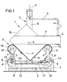
- a wrapping machine 1 for wrapping cuboid bale B with an only indicated Wrapping film F is composed of a rolling device 2 for circulating the bales of good B around a substantially horizontal rolling axis A and a winding device 3 to apply the wrapping film F together.
- This winding device 3 has a film deduction 4, which on a cantilever arm 5 about a to the circulating device 2 approximately central vertical axis V rotatably and driven on a gallows-shaped post 6 and wraps wrapping film F around the bale as it rotates. Because during this circulation of the bales circulates at the same time, there is a complete wrapping of the good bale B with wrapping foil F.
- the rolling device 2 consists of a on both sides about a horizontal pivot axis S on a machine frame 7 for tipping the fully wound bale B of the base frame 8 supported in a swiveling manner, on which two pivoting axes P which are parallel to one another and which are parallel to one another are pivotally mounted Pendulum supports 9, 10 are mounted and effective at the same height, the Gutballen B have between receiving funds 11.
- the two pendulum supports 9, 10 are with each other via a coupling rod 12 in the sense of counter-rotating movements coupled, one articulation point 13 above and the other articulation point 14 lie below the associated pendulum axis P.
- the conveyor belt 17 below the conveyor rollers 15, 16 via a return roller 18 in the area the pendulum support 9 and a tensioning device 19 rotates in the area of the pendulum support 10 and the conveyor run of the conveyor belt 17 between the conveyor rollers 15, 16 forms a sag H conforming to the shape of the bale.
- the conveyor belt 17 driven via one of the conveyor rollers, there is a circulation of the bale, the sag taking up the bale corresponding to the Rolling position of the bale increased or decreased.
- the movement coupling of the pendulum supports 9, 10 but ensures that the shape of the sag or the pendulum movement the pendulum supports are symmetrical to the center of the roller and thus centered the bale movement takes place during the circulation.
- FIG. 2 there are two horizontal swivel axes S hinged to pincer-like supports 81 of the machine frame 7
- Pendulum supports 9, 10 and as funding 11 are on each pendulum support 9, 10
- a pair of conveyor rollers 20, 21, 22, 23 are provided, the pendulum supports for their storage 9, 10 have two support arms 24, 25 which are angled relative to one another.
- the coupling rod 12 connects the pendulum supports 9, 10 also in the sense of an opposite pivoting movement and here too the one articulation point 13 is above and the other articulation point 14 below the associated pendulum axis P.
Landscapes
- Life Sciences & Earth Sciences (AREA)
- Environmental Sciences (AREA)
- Storage Of Harvested Produce (AREA)
- Basic Packing Technique (AREA)
- Packaging Of Special Articles (AREA)
- Wrappers (AREA)
Description
- Fig. 1
- eine erfindungsgemäße Wickelmaschine in Seitenansicht und
- Fig. 2
- ein anderes Ausführungsbeispiel einer Wälzeinrichtung dieser Wickelmaschine ebenfalls in Seitenansicht.
Claims (1)
- Wickelmaschine (1) zum Umwickeln quaderförmiger Gutballen (B) mit Hüllfolien (F) od. dgl., bestehend aus einer Wälzeinrichtung (2) zum Umwälzen der Ballen (B) um eine im wesentlichen horizontale Wälzachse (A) und einer Wckeleinrichtung (3) zum Aufbringen der Hüllfolien (F) mit einem relativ zur Wälzeinrichtung um eine Vertikalachse (V) umlaufenden Folienabzug (4), wobei die Wälzeinrichtung (2) zwei um zueinander parallele horizontale Pendelachsen (P) schwenkbar gelagerte Pendelstützen (9, 10) mit in gleicher Höhe angeordneten, zwischen sich die Gutballen (B) aufnehmenden Fördermitteln (11) aufweist, dadurch gekennzeichnet, daß die Pendelstützen (9, 10) über eine Koppeleinrichtung (12) im Sinne gegengerichteter Schwenkbewegungen miteinander gekoppelt sind.
Applications Claiming Priority (3)
| Application Number | Priority Date | Filing Date | Title |
|---|---|---|---|
| AT0046397A AT404533B (de) | 1997-03-17 | 1997-03-17 | Wickelmaschine zum umwickeln quaderförmiger gutballen mit hüllfolien |
| AT46397 | 1997-03-17 | ||
| AT463/97 | 1997-03-17 |
Publications (2)
| Publication Number | Publication Date |
|---|---|
| EP0865722A1 EP0865722A1 (de) | 1998-09-23 |
| EP0865722B1 true EP0865722B1 (de) | 2002-06-05 |
Family
ID=3491301
Family Applications (1)
| Application Number | Title | Priority Date | Filing Date |
|---|---|---|---|
| EP98890072A Expired - Lifetime EP0865722B1 (de) | 1997-03-17 | 1998-03-16 | Wickelmaschine zum Umwickeln quaderförmiger Gutballen mit Hüllfolien |
Country Status (3)
| Country | Link |
|---|---|
| EP (1) | EP0865722B1 (de) |
| AT (2) | AT404533B (de) |
| DE (1) | DE59804278D1 (de) |
Cited By (1)
| Publication number | Priority date | Publication date | Assignee | Title |
|---|---|---|---|---|
| CN106535616A (zh) * | 2014-06-26 | 2017-03-22 | 库恩-海尔德罗普有限责任公司 | 具有拾取装置的农用设备 |
Families Citing this family (7)
| Publication number | Priority date | Publication date | Assignee | Title |
|---|---|---|---|---|
| IES970777A2 (en) * | 1997-07-25 | 1999-01-13 | Arboc Ltd | A bale wrapping machine |
| FI110423B (fi) * | 2000-04-07 | 2003-01-31 | Wrapmatic Oy | Menetelmä ja laitteisto rehupaalin muovittamiseksi |
| NL2004611C2 (nl) * | 2010-04-26 | 2011-10-27 | Knoll Geb | Inrichting voor het met een folie omwikkelen van een baal maaigoed en combinatie daarvan met een balenpers. |
| NO2870856T3 (de) * | 2013-11-12 | 2018-03-31 | ||
| DE102015004274A1 (de) * | 2015-04-08 | 2016-11-10 | Usines Claas France S.A.S. | Vorrichtung zum Umwickeln von Erntegutballen |
| DE102015214708A1 (de) * | 2015-07-31 | 2017-02-02 | Deere & Company | Ballenwickeleinrichtung, Erntebergungsgerät und Verfahren |
| CN116267249A (zh) * | 2023-04-14 | 2023-06-23 | 沈阳农业大学 | 一种摆动式草捆包膜机 |
Family Cites Families (4)
| Publication number | Priority date | Publication date | Assignee | Title |
|---|---|---|---|---|
| NO176133C (no) | 1991-11-22 | 1997-10-15 | Tellefsdal As | Innretning ved en pakkemaskin for emballering av en stråfôrballe |
| FR2687040B1 (fr) * | 1992-02-10 | 1994-05-06 | Doucet Freres Sa | Machine a enrubanner des objets parallelepipediques ou rectangulaires ou cylindriques, notamment des balles de paille, fourrage, ensilage. |
| AT407143B (de) | 1993-07-20 | 2000-12-27 | Goeweil Herbert | Wickelmaschine zum umwickeln quaderförmiger gutballen mit hüllfolien od. dgl. |
| SE503043C2 (sv) * | 1995-01-18 | 1996-03-18 | Staffan Soederberg | Förfarande och anordning vid emballering medelst banformigt material |
-
1997
- 1997-03-17 AT AT0046397A patent/AT404533B/de not_active IP Right Cessation
-
1998
- 1998-03-16 AT AT98890072T patent/ATE218270T1/de not_active IP Right Cessation
- 1998-03-16 EP EP98890072A patent/EP0865722B1/de not_active Expired - Lifetime
- 1998-03-16 DE DE59804278T patent/DE59804278D1/de not_active Expired - Lifetime
Cited By (2)
| Publication number | Priority date | Publication date | Assignee | Title |
|---|---|---|---|---|
| CN106535616A (zh) * | 2014-06-26 | 2017-03-22 | 库恩-海尔德罗普有限责任公司 | 具有拾取装置的农用设备 |
| CN106535616B (zh) * | 2014-06-26 | 2021-07-06 | 库恩-海尔德罗普有限责任公司 | 具有拾取装置的农用设备 |
Also Published As
| Publication number | Publication date |
|---|---|
| AT404533B (de) | 1998-12-28 |
| ATA46397A (de) | 1998-05-15 |
| ATE218270T1 (de) | 2002-06-15 |
| DE59804278D1 (de) | 2002-07-11 |
| EP0865722A1 (de) | 1998-09-23 |
Similar Documents
| Publication | Publication Date | Title |
|---|---|---|
| DE3420134C2 (de) | Vorrichtung zum Ein- und Ausladen von Werkstücken in einer Presse | |
| DE60133334T2 (de) | Verfahren und Vorrichtung zum Umhüllen von Gegenständen | |
| DE4308646C2 (de) | Erntegut-Rundballenformmaschine | |
| DE69208828T2 (de) | Vorrichtung zum Umwickeln von ringförmigen Gegenständen | |
| DE69214097T2 (de) | Verpackungsmaschine zum Verpacken von Strohballen | |
| EP0865722B1 (de) | Wickelmaschine zum Umwickeln quaderförmiger Gutballen mit Hüllfolien | |
| DE1158420B (de) | Vorrichtung zum zickzackfoermigen Einlegen von Faserbaendern oder Fadenstraengen in Ablegebehaelter | |
| DE69231361T2 (de) | Verfahren und vorrichtung zum herstellen einer reihe von gepressten pflanzenballen in einer umhüllungsfolie | |
| DE2061719C2 (de) | Einrichtung zum volumetrischen Dosieren von Schüttgut | |
| EP0681980B1 (de) | Vorrichtung zum Schwenken einer changierenden Flachkanne an einer Faserband abliefernden Textilmaschine | |
| DE4425428B4 (de) | Wickelmaschine zum Umwickeln quaderförmiger Gutballen mit Hüllfolien o. dgl. | |
| DE1247910B (de) | Vorrichtung zum Ablegen eines Faserstranges oder eines Faserbandes in einem Behaelter | |
| DE3407135A1 (de) | Vorrichtung zum ablegen von lunte in eine rotierende kanne | |
| DE4243406A1 (de) | Verfahren und Vorrichtung zur Herstellung von mit Folien umwickelten Rundpreßballen | |
| DE10334681B3 (de) | Vorrichtung zum Umhüllen oder Verpacken von insbesondere landwirtschaftlichen Erntegutballen | |
| EP2853145B1 (de) | Rundballenpresse | |
| DE1574320B2 (de) | Haltevorrichtung fuer einen wickel, insbes. stoffwickel in stofflegemaschinen | |
| DE4313240C2 (de) | Verfahren zum Umwickeln von zylindrischem Gut | |
| EP0829197A2 (de) | Wickelmaschine zum Umwickeln zylindrischer Gutballen mit einer Hüllfolie | |
| DE2414860A1 (de) | Geraet zur einlagerung eines bandes aus synthetischen textilfasern in eine spinnkanne | |
| DE69122779T2 (de) | Einwickelvorrichtung fürzigarren | |
| DE3037812A1 (de) | Fahrbare grossballenpresse | |
| DE19740191A1 (de) | Verschweißvorrichtung zur Verschweißung von endlosen, übereinandergelegten Verpackungsmaterialstreifen zur Bildung von Mehrfachblasenpackungen zur Aufnahme von Produkten | |
| DE1958756C3 (de) | Aufladeeinrichtung für auf dem Boden liegendes Halmgut | |
| DE3021506A1 (de) | Landwirtschaftliche ballenpresse mit durch laufrollen gefuehrtem presskolben |
Legal Events
| Date | Code | Title | Description |
|---|---|---|---|
| PUAI | Public reference made under article 153(3) epc to a published international application that has entered the european phase |
Free format text: ORIGINAL CODE: 0009012 |
|
| AK | Designated contracting states |
Kind code of ref document: A1 Designated state(s): AT BE CH DE DK FI FR GB IE IT LI NL SE |
|
| AX | Request for extension of the european patent |
Free format text: AL;LT;LV;MK;RO;SI |
|
| 17P | Request for examination filed |
Effective date: 19990203 |
|
| AKX | Designation fees paid |
Free format text: AT BE CH DE DK FI FR GB IE IT LI NL SE |
|
| RBV | Designated contracting states (corrected) |
Designated state(s): AT BE CH DE DK FI FR GB IE IT LI NL SE |
|
| GRAG | Despatch of communication of intention to grant |
Free format text: ORIGINAL CODE: EPIDOS AGRA |
|
| GRAG | Despatch of communication of intention to grant |
Free format text: ORIGINAL CODE: EPIDOS AGRA |
|
| GRAH | Despatch of communication of intention to grant a patent |
Free format text: ORIGINAL CODE: EPIDOS IGRA |
|
| 17Q | First examination report despatched |
Effective date: 20010726 |
|
| GRAH | Despatch of communication of intention to grant a patent |
Free format text: ORIGINAL CODE: EPIDOS IGRA |
|
| GRAA | (expected) grant |
Free format text: ORIGINAL CODE: 0009210 |
|
| AK | Designated contracting states |
Kind code of ref document: B1 Designated state(s): AT BE CH DE DK FI FR GB IE IT LI NL SE |
|
| PG25 | Lapsed in a contracting state [announced via postgrant information from national office to epo] |
Ref country code: NL Free format text: LAPSE BECAUSE OF FAILURE TO SUBMIT A TRANSLATION OF THE DESCRIPTION OR TO PAY THE FEE WITHIN THE PRESCRIBED TIME-LIMIT Effective date: 20020605 Ref country code: GB Free format text: LAPSE BECAUSE OF FAILURE TO SUBMIT A TRANSLATION OF THE DESCRIPTION OR TO PAY THE FEE WITHIN THE PRESCRIBED TIME-LIMIT Effective date: 20020605 Ref country code: FR Free format text: LAPSE BECAUSE OF FAILURE TO SUBMIT A TRANSLATION OF THE DESCRIPTION OR TO PAY THE FEE WITHIN THE PRESCRIBED TIME-LIMIT Effective date: 20020605 |
|
| REF | Corresponds to: |
Ref document number: 218270 Country of ref document: AT Date of ref document: 20020615 Kind code of ref document: T |
|
| REG | Reference to a national code |
Ref country code: GB Ref legal event code: FG4D Free format text: NOT ENGLISH |
|
| REG | Reference to a national code |
Ref country code: CH Ref legal event code: EP |
|
| REG | Reference to a national code |
Ref country code: IE Ref legal event code: FG4D Free format text: GERMAN |
|
| REF | Corresponds to: |
Ref document number: 59804278 Country of ref document: DE Date of ref document: 20020711 |
|
| PG25 | Lapsed in a contracting state [announced via postgrant information from national office to epo] |
Ref country code: SE Free format text: LAPSE BECAUSE OF FAILURE TO SUBMIT A TRANSLATION OF THE DESCRIPTION OR TO PAY THE FEE WITHIN THE PRESCRIBED TIME-LIMIT Effective date: 20020905 Ref country code: DK Free format text: LAPSE BECAUSE OF FAILURE TO SUBMIT A TRANSLATION OF THE DESCRIPTION OR TO PAY THE FEE WITHIN THE PRESCRIBED TIME-LIMIT Effective date: 20020905 |
|
| REG | Reference to a national code |
Ref country code: CH Ref legal event code: NV Representative=s name: CABINET ROLAND NITHARDT CONSEILS EN PROPRIETE INDU |
|
| NLV1 | Nl: lapsed or annulled due to failure to fulfill the requirements of art. 29p and 29m of the patents act | ||
| GBV | Gb: ep patent (uk) treated as always having been void in accordance with gb section 77(7)/1977 [no translation filed] |
Effective date: 20020605 |
|
| EN | Fr: translation not filed | ||
| PG25 | Lapsed in a contracting state [announced via postgrant information from national office to epo] |
Ref country code: AT Free format text: LAPSE BECAUSE OF NON-PAYMENT OF DUE FEES Effective date: 20030316 |
|
| PG25 | Lapsed in a contracting state [announced via postgrant information from national office to epo] |
Ref country code: BE Free format text: LAPSE BECAUSE OF NON-PAYMENT OF DUE FEES Effective date: 20030331 |
|
| PLBE | No opposition filed within time limit |
Free format text: ORIGINAL CODE: 0009261 |
|
| STAA | Information on the status of an ep patent application or granted ep patent |
Free format text: STATUS: NO OPPOSITION FILED WITHIN TIME LIMIT |
|
| 26N | No opposition filed |
Effective date: 20030306 |
|
| BERE | Be: lapsed |
Owner name: *GOWEIL HERBERT Effective date: 20030331 |
|
| PGFP | Annual fee paid to national office [announced via postgrant information from national office to epo] |
Ref country code: CH Payment date: 20040611 Year of fee payment: 7 |
|
| PG25 | Lapsed in a contracting state [announced via postgrant information from national office to epo] |
Ref country code: LI Free format text: LAPSE BECAUSE OF NON-PAYMENT OF DUE FEES Effective date: 20050331 Ref country code: CH Free format text: LAPSE BECAUSE OF NON-PAYMENT OF DUE FEES Effective date: 20050331 |
|
| REG | Reference to a national code |
Ref country code: CH Ref legal event code: PL |
|
| PGFP | Annual fee paid to national office [announced via postgrant information from national office to epo] |
Ref country code: IE Payment date: 20160225 Year of fee payment: 19 Ref country code: DE Payment date: 20160317 Year of fee payment: 19 |
|
| PGFP | Annual fee paid to national office [announced via postgrant information from national office to epo] |
Ref country code: FI Payment date: 20160330 Year of fee payment: 19 |
|
| PGFP | Annual fee paid to national office [announced via postgrant information from national office to epo] |
Ref country code: IT Payment date: 20160330 Year of fee payment: 19 |
|
| REG | Reference to a national code |
Ref country code: DE Ref legal event code: R119 Ref document number: 59804278 Country of ref document: DE |
|
| PG25 | Lapsed in a contracting state [announced via postgrant information from national office to epo] |
Ref country code: FI Free format text: LAPSE BECAUSE OF NON-PAYMENT OF DUE FEES Effective date: 20170316 |
|
| REG | Reference to a national code |
Ref country code: IE Ref legal event code: MM4A |
|
| PG25 | Lapsed in a contracting state [announced via postgrant information from national office to epo] |
Ref country code: DE Free format text: LAPSE BECAUSE OF NON-PAYMENT OF DUE FEES Effective date: 20171003 |
|
| PG25 | Lapsed in a contracting state [announced via postgrant information from national office to epo] |
Ref country code: IT Free format text: LAPSE BECAUSE OF NON-PAYMENT OF DUE FEES Effective date: 20170316 Ref country code: IE Free format text: LAPSE BECAUSE OF NON-PAYMENT OF DUE FEES Effective date: 20170316 |