EP0865732B2 - Machine for automatically tying meat packed in casings - Google Patents
Machine for automatically tying meat packed in casings Download PDFInfo
- Publication number
- EP0865732B2 EP0865732B2 EP98810106A EP98810106A EP0865732B2 EP 0865732 B2 EP0865732 B2 EP 0865732B2 EP 98810106 A EP98810106 A EP 98810106A EP 98810106 A EP98810106 A EP 98810106A EP 0865732 B2 EP0865732 B2 EP 0865732B2
- Authority
- EP
- European Patent Office
- Prior art keywords
- cord
- bobbin
- tying
- sausage skin
- filled sausage
- Prior art date
- Legal status (The legal status is an assumption and is not a legal conclusion. Google has not performed a legal analysis and makes no representation as to the accuracy of the status listed.)
- Expired - Lifetime
Links
- 235000013372 meat Nutrition 0.000 title claims description 5
- 235000013580 sausages Nutrition 0.000 claims abstract description 92
- 238000006073 displacement reaction Methods 0.000 claims description 5
- 230000000903 blocking effect Effects 0.000 claims description 2
- 239000003562 lightweight material Substances 0.000 claims description 2
- 230000027455 binding Effects 0.000 description 10
- 238000009739 binding Methods 0.000 description 10
- 238000000034 method Methods 0.000 description 9
- 238000004804 winding Methods 0.000 description 7
- 238000004519 manufacturing process Methods 0.000 description 4
- 238000010276 construction Methods 0.000 description 3
- 241001237745 Salamis Species 0.000 description 2
- 230000001133 acceleration Effects 0.000 description 2
- 238000012423 maintenance Methods 0.000 description 2
- 235000015175 salami Nutrition 0.000 description 2
- 240000005561 Musa balbisiana Species 0.000 description 1
- 235000018290 Musa x paradisiaca Nutrition 0.000 description 1
- 230000004323 axial length Effects 0.000 description 1
- 230000015572 biosynthetic process Effects 0.000 description 1
- 239000003795 chemical substances by application Substances 0.000 description 1
- 150000001875 compounds Chemical class 0.000 description 1
- 230000006835 compression Effects 0.000 description 1
- 238000007906 compression Methods 0.000 description 1
- 230000000694 effects Effects 0.000 description 1
- 239000000945 filler Substances 0.000 description 1
- 238000005429 filling process Methods 0.000 description 1
- 239000000463 material Substances 0.000 description 1
- 238000003825 pressing Methods 0.000 description 1
- 238000005096 rolling process Methods 0.000 description 1
Images


Classifications
-
- A—HUMAN NECESSITIES
- A22—BUTCHERING; MEAT TREATMENT; PROCESSING POULTRY OR FISH
- A22C—PROCESSING MEAT, POULTRY, OR FISH
- A22C11/00—Sausage making ; Apparatus for handling or conveying sausage products during manufacture
- A22C11/12—Apparatus for tying sausage skins ; Clipping sausage skins
- A22C11/122—Apparatus for tying sausage skins ; Clipping sausage skins by forming knots
Definitions
- the present invention relates to a machine for the automatic setting of meat filled in a sausage skin by means of a string according to the preamble of patent claim 1.
- the first of these methods consists in real knots being made at the constriction points of the sausages: this method is used in sausages in manual mode, while the mechanical execution is the subject of various Swiss patents under the numbers 579351 . 587610 the same applicant.
- the other method which is generally used today, renounces the formation of real knots and reaches the subdivision of the sausage skin into individual sections to form the salami sausages and the other known sausages by means of simple setting, ie by the setting point a certain number Schnurwindungen - Usually 1 to 3 turns - are applied, which are sufficient for a permanent subdivision of the filled sausage skin, especially when the application of the line windings, the skin and / or the cord are moist.
- the known machines for the automatic setting of meat filled in a skin which work according to this latter method, are provided with a cord package which circles the sausage skin one or more times, thereby creating one or more twine twines on the tying site, where the sausage skin was previously concentrated by means of constricting agents.
- the disadvantage of these known machines is that the cord coils used must revolve around the sausage skin, with the result that string coils of small dimensions must be used, so that the forces exerted due to the acceleration and deceleration of the coil forces within limits can be kept. Therefore, the cord coils must be replaced frequently, which reduces the productivity of the machine.
- This device lacks all the prerequisites, such as an efficient control of the cord tension during and after the Abbindeoperation, the safe control of the mass of the cord reel during its rotation - so when turning off the coil no unnecessary pieces of string are unwound from the bobbin - the continuity of the work (the cord is cut off after each binding), for an automation of the work: it is merely a hand-operated auxiliary device, which is to help the butcher at very low speed - virtually no faster than if he would place conventional knots by hand around the sausages - To realize individual bindings.
- this construction and above all the DE-GM, has shown the application of a cord coil orbiting the sausage coaxially.
- the coil, which receives the Abbindeschnur is arranged coaxially with the axis of symmetry of the filled sausage skin, which latter passes through the coil in the middle, and the inner diameter is substantially limited only by the full sausage skin pass through with a corresponding diameter but is not limited in its axial length, the only limitation being the problems associated with acceleration and deceleration of the masses, but not unbalance problems.
- the cord spool concentrically rotates about its axis of symmetry and therefore does not allow imbalance forces to arise, as was the case with the previous spools of the known automatic setting machines according to the prior art, which revolved around the longitudinal axis of the sausage skin.
- the cord length wound on the bobbin can be extended many times (on the order of ten times longer), which means that the machine has to be parked much less frequently for bobbin replacement.
- the absence of imbalance forces acting on the tying machine allows for an increase in working speed of at least 20 to 50% without overloading both the tying cord and the sausage skin arises.
- the machine according to the present invention thanks to the complete control of the tension conditions in the line, produces setting points in the filled sausage of consistent and controlled quality, irrespective of the weight of the line spool used, which changes over time.
- FIGS. 1 and 2 show the basic structure of the machine in two different views.
- the reference numeral 1 a coil holder or boat is indicated, which is mounted in a rolling bearing 4, which is installed in a carrier 20.
- the coil holder 1 carries a flange 1a.
- a cord coil 2 is attached, which preferably consists of a lightweight material, such as plastic, on which the cord 28 is wound in turns, which serves for setting the filled sausages or the like.
- the bobbin holder 1 is rotated together with the string bobbin 2 by means of a servo motor 12 and a toothed belt 11 engaged with a pulley integral with the bobbin holder 1.
- the brushless servo motor with the drive pulley 10 is using controlled by means (not shown) in such a way as to give the bobbin holder a precisely fixed number (usually 2 or 3) revolutions which produce a corresponding number of turns of string around the sausage skin, as explained in more detail below.
- a flange 3 with an opening 29 in its center is via two drilled out posts 18, in the two pins 27 ( Fig. 8 ) are connected to the flange 1a of the bobbin holder 1 so that the flange 3 in the mounted state together with the bobbin holder 1 and the flange 1a forms a unit.
- the flange 3 can be released from the flange 1 a, when the pins 27 are pulled out of the supports 18 after loosening fastening elements, not shown, so that a cord-coil 2 can be attached to the hub of the bobbin holder 1.
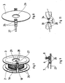
- the pins 27 In at least one of the pins 27 (of which normally at least 2 are provided diametrically opposed to each other on the flange to ensure proper attachment of the flange 3 to the flange 1a) are two passage openings 26 (see also Figs FIGS. 7, 8 and 9 ), by the first of which the cord 28 is made from the surface of the spool on which it is wound, and from where it is deflected axially over a short distance and then at a point above (with respect to the spool 2) of the flange 3 is deflected radially through the second opening 26.
- the string 28 (see the Fig. 7 ) is thus guided against the center of the sputeholder 1 through the opening 29 in the middle of the flange 3.
- the cord is braked by means of an adjustable braking device according to the voltage required to set the product.
- the brake device consists of a brake plate 6 (see also the Fig. 9 , which also shows its details), which is fixed to a pivotable lever 7 and is pressed by a compression spring 8 against the pin 27. It is a friction brake that clamps the cord 28 between the plate 6 and the pin 27.
- the said braking device aims at braking the cord during the setting process, during which the bobbin holder 1 and the bobbin 2 rotate and deposit the cord windings on the sausage skin.
- the brake must be released: for this purpose, a stationary piston 9, which presses on the end of the lever 7, which is opposite the end of the lever end, is used the brake disc 6 is located, wherein the spring force of the spring 8 overcome and the cord 28 is released from the clamping of the brake.
- FIGS. 1 and 2 designated by the arrow f, carries a roller 23 whose axis of rotation is parallel to the axis of rotation of the bobbin holder.
- an actuating piston 22 for example, a pneumatic piston
- the device for concentrating the filled sausage skin at the setting point and thus for compressing the filled sausage skin from two pairs of pliers levers 13, 14 (the details of which in the FIGS. 5 and 6 are shown).
- the front forceps 13 ( Fig. 6 ) is referred to as the front, as it is, in the direction indicated by the arrow f feeding direction of the sausage, before the Abbindestelle. It is fixed with respect to the feed direction in space and the sausage is compressed when closing the pliers head, which takes place by means of two actuating piston 17, between the two V-shaped elements perpendicular to the feed direction. The pressing of the forceps 13 narrows the filled sausage skin at a position immediately before the setting point.
- the rear tongs 14 (FIG. Fig. 5 ) is designated as such, as it is, seen in the feed direction, after the Abbindetician:
- This forceps consists of two long arms which extend axially through the coil holder 1, and which are attached to a vertical pin.
- the actuating pistons 19 provide the closing of the forceps 14 in a horizontal plane, wherein the sausage skin between the two V-shaped surfaces, which are similar to those of the forceps 13, is narrowed.
- the mechanism of the forceps 14 is then preferably mounted on a carriage 15 on which the forceps 14 can be axially displaced over a short distance.
- Fig. 4 is a further detail of the inventive device shown in the assembled state in the Fig. 2 is shown. It is a pivotable lever 24, the front end is disposed between the front pliers 13 and the rear pliers 14 and performs a lateral pivoting movement.
- This lever thus has the task to keep the string in the area of the front tongs 13 (and to prevent them from being too far behind the tying windings that have just been applied), so that a second tying 34 is at a distance S of the first binding 33 (see also the Fig. 11 ) is created safely and clearly separated from the first one.
- the two separately arranged bindings are important so that the sausages can be subsequently separated at the narrowed section between the two bindings without the risk that the filled material escapes.
- the assembly consisting of the cord-spool 2, the rotating spool holder 1 with the flange 1a and the flange 3 attached thereto by means of the supports 18 (only one of which is visible) and the pins 27 in which the through-holes 26 are provided, and on soft the cord brakes 6, 7, 8 are mounted, is in the Fig. 7 shown separately while the Fig. 8 shows the dissolved flange 1 from the flange 3, which can better explain the way in which the latter is attached to the flange 1a.
- the inner diameter of the bore of the coil 2, which receives the cord depends on the largest diameter of the filled sausage skin, while the outer diameter D of the coil 2 is at least twice as large as the sausage diameter.
- the diameter of the spool 2, and thus also that of the spool holder 1, is preferably adapted to the diameter of the sausages to be manufactured so that the available useful volume for winding the cord on the spool can be maximally utilized. For the production of thinner sausages, therefore, coils 2 of smaller bore diameter can be used.
- the present invention offers as one of its main advantages in particular the ability to work with coils 2 of large filling capacity, so that the frequency of machine downtime for bobbin change is substantially reduced.
- the outer diameter of the spool 2 is more than 15 cm, which means that (in comparison with the cord spools used today on machines according to the prior art which have an outer diameter of at most about 10 cm), the uninterrupted service life, before the next bobbin change is necessary, can be significantly extended.
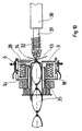
- Fig. 10 the mode of operation of the machine according to the invention is then shown schematically during operation.
- the filling device 30, on the filler pipe 31 a sausage skin 32 "accordion-like" is attached.
- the controlled rotational movement of the bobbin holder 1 which carries the cord bobbin 2, with closed nippers 13 and 14 and by means of the braking system 6, 7 and 8 allows the application of a desired number of cord windings (the programming of the brushless servo motor 12th is determined) on the constricted sausage skin, wherein a constriction is formed.
- the binding turns are precise on the Wurst skin "applied” without that a relative movement between string and sausage skin can be done so that there is no danger that the sausage skin 32 would be damaged.
- the cord 28 is thus relaxed (or is only under a reduced tension), and the filling device 30 may continue the filling of the sausage skin 32, which moves freely while pulling the relaxed cord, which does not have any tensile force on the nascent Sausage exercises.
- the filling device is stopped, the pliers 13 and 14 close and narrow the filled sausage skin and thus create the conditions for the first setting.
- the lever 21 returns to hold the spool 2 on the spool holder 1, the motor 12 rotates the aggregate, and a new binding is applied to the sausage skin. This process always repeats in this way.
- the production capacity of the machine according to the invention is much higher than that of the hitherto known setting machines, which have the disadvantage of large rotating imbalance masses, and allows the use of substantially (up to 10 times) heavier line spools than are used on the machines known today can. Overall, this results in significant economic savings associated with simplified maintenance just because of the lack of excessive dynamic forces.
- the inventive machine can work with natural casings or with artificial sausage skins, while the string, or the twine, dry or preferably before moist can be used. Using moistened cord results in stronger bonds.
- the machine can also be equipped with an independent feeding system for filling.
Landscapes
- Life Sciences & Earth Sciences (AREA)
- Engineering & Computer Science (AREA)
- Wood Science & Technology (AREA)
- Zoology (AREA)
- Food Science & Technology (AREA)
- Processing Of Meat And Fish (AREA)
- Meat, Egg Or Seafood Products (AREA)
- Package Closures (AREA)
- Basic Packing Technique (AREA)
Abstract
Description
Die vorliegende Erfindung betrifft eine Maschine zum automatischen Abbinden von in eine Wursthaut eingefülltem Fleisch mittels einer Schnur bzw. Bindfaden gemäss dem Oberbegriff des Patentanspruchs 1.The present invention relates to a machine for the automatic setting of meat filled in a sausage skin by means of a string according to the preamble of patent claim 1.
Aus der Praxisanwendung sowie aus der Patentliteratur sind zwei grundsätzliche Verfahren bekannt zum automatischen Abbinden der eingefüllten Wurstwaren, z. B. Salami, Salsiz, Würsten, usw.From the practice application as well as from the patent literature, two basic methods are known for automatically setting the filled sausages, z. Salami, salsiz, sausages, etc.
Das erste dieser Verfahren besteht darin, dass an den Einschnürstellen der Würste echte Knoten ausgeführt werden: Dieses Verfahren wird in Wurstereien beim Handbetrieb angewendet, während die mechanische Ausführung Gegenstand verschiedener Schweizer Patente unter den Nummern
Dieses Verfahren, zweifelsohne ideal unter dem Gesichtspunkt der Qualität der ausgeführten Knoten, weist den Nachteil auf, dass keine hohe Produktionsleistung zu erreichen ist, da die Knüpf-Vorrichtungen kompliziert sowie im Unterhalt heikel und aufwendig sind.This method, undoubtedly ideal from the point of view of the quality of the knots executed, has the disadvantage that high production efficiency can not be achieved because the knotting devices are complicated and expensive to maintain.
Das andere Verfahren, das heute allgemein angewendet wird, verzichtet auf die Bildung echter Knoten und erreicht die Unterteilung der Wursthaut in einzelne Abschnitte zur Bildung der Salami-Würste und der anderen bekannten Würste mittels einfachem Abbinden, d.h. indem am Abbinde-Punkt eine bestimmte Anzahl Schnurwindungen - normalerweise 1 bis 3 Windungen - angelegt werden, die für eine dauerhafte Unterteilung der eingefüllten Wursthaut-genügen, insbesondere wenn beim Anlegen der Schnurwindungen die Haut und/oder die Schnur feucht sind. Die Praxiserfahrung hat gezeigt, dass dieses Abbinden mittels "Umwindungen" die Herstellung richtig und dauernd ausgebildeten Würsten gewährleistet, insbesondere wenn, wie es üblicherweise ausgeführt wird, zwei Abbindepunkte in kurzem Abstand - einige Millimeter - angelegt werden, zwischen denen die Wursthaut abgeschnitten wer den kann, um die einzelnen Würste abzutrennen.The other method, which is generally used today, renounces the formation of real knots and reaches the subdivision of the sausage skin into individual sections to form the salami sausages and the other known sausages by means of simple setting, ie by the setting point a certain number Schnurwindungen - Usually 1 to 3 turns - are applied, which are sufficient for a permanent subdivision of the filled sausage skin, especially when the application of the line windings, the skin and / or the cord are moist. The practical experience has shown that this setting by means of "convolutions" ensures the production of properly and continuously trained sausages, especially when, as it is usually carried out two Abbindepunkte a short distance - a few millimeters - are created, between which cut the sausage skin who can to separate the individual sausages ,
Die bekannten Maschinen zum automatischen Abbinden von in eine Haut eingefülltem Fleisch, die nach diesem letzteren Verfahren arbeiten, sind mit einer Schnur-Spulenpackung versehen, welche die Wursthaut ein- oder mehrmals umkreist, um dabei eine oder mehr Schnur-Windungen auf der Abbindestelle anzulegen, an der die Wursthaut vorgängig mittels Einengungsmitteln eingeengt wurde. Der Nachteil dieser bekannten Maschinen besteht darin, dass die verwendeten Schnur-Spulen um die Wursthaut kreisen müssen, was zur Folge hat, dass Schnur-Spulen von kleiner Abmessung verwendet werden müssen, damit die infolge der Beschleunigung und der Abbremsung der Spule ausgeübten Kräfte in Grenzen gehalten werden können. Daher müssen die Schnur-Spulen häufig ausgewechselt werden, was die Produktivität der Maschine verringert.The known machines for the automatic setting of meat filled in a skin, which work according to this latter method, are provided with a cord package which circles the sausage skin one or more times, thereby creating one or more twine twines on the tying site, where the sausage skin was previously concentrated by means of constricting agents. The disadvantage of these known machines is that the cord coils used must revolve around the sausage skin, with the result that string coils of small dimensions must be used, so that the forces exerted due to the acceleration and deceleration of the coil forces within limits can be kept. Therefore, the cord coils must be replaced frequently, which reduces the productivity of the machine.
Es ist weiter aus der Praxis und durch die deutsche Gebrauchsmusteranmeldung Nr.
Ziel der vorliegenden Erfindung ist es daher, die Nachteile gemäss dem Stand der Technik der Abbindemaschinen für eingefülltes Fleisch oder ähnliche Produkte zu überwinden und eine Maschine zu schaffen, mittels der die Beschränkungen der Geschwindigkeit und damit der Produktivität überwunden werden können und ein automatisierter Betrieb realisierbar wird. Insbesondere geht es darum, die Häufigkeit der Stillstände für das Auswechseln der Schnurspulen zu verringern und zusätzlich die Unwuchtprobleme auszuschalten, die infolge der beträchtlichen um den Abbindepunkt rotierenden Massen entstehen und die entsprechend wechselnden Kräfte auf die Elemente der Maschine einwirken lassen und die die Arbeitsbedingungen generell beeinträchtigen. Die vorliegende Erfindung bezweckt daher, eine Maschine zu schaffen, die ein grosse Zahl von Abbindungen pro Zeiteinheit bei gleichbleibender Qualität und bei verringertem Wartungsaufwand, insbesondere bezüglich des Schnurspulenwechsels, ausführen kann.
Diese Ziele werden erreicht mittels einer Maschine zum Abbinden einer gefüllten Wursthaut mit den kennzeichnenen Eigenschaften gemäss dem Anspruch 1.It is therefore an object of the present invention to overcome the prior art drawbacks of stuffed meat or similar products and to provide a machine which can overcome the limitations of speed and hence productivity and make automated operation feasible , In particular, it is about reducing the frequency of stoppages for changing the string bobbins and also eliminating the imbalance problems that arise as a result of the considerable masses rotating about the setting point and the correspondingly varying forces acting on the elements of the machine and generally affecting the working conditions , The present invention therefore aims to provide a machine that can perform a large number of bindings per unit of time with the same quality and with reduced maintenance, especially with respect to the cord coil change.
These objects are achieved by means of a machine for setting a filled sausage skin with the characterizing properties according to claim 1.
Dank der Auslegung, dass die Spule, welche die Abbindeschnur aufnimmt, koaxial mit der Symmetrieachse der gefüllten Wursthaut angeordnet ist, welch letztere die Spule in deren Mitte durchquert, und deren Innendurchmesser im Wesentlichen nur dadurch begrenzt ist, dass die volle Wursthaut mit entsprechendem Durchmesser durchtreten können muss, aber nicht in ihrer achsialen Länge begrenzt ist, wobei die einzige Begrenzung durch die Probleme im Zusammenhang mit der Beschleunigung und der Abbremsung der Massen gegeben ist, jedoch nicht durch Unwuchtprobleme. Die Schnurspule rotiert konzentrisch um ihre Symmetrieachse un lässt daher keine Unwuchtkräfte entstehen, wie dies bei den bisherigen Spulen der bekannten automatischen Abbindemaschinen gemäss dem Stand der Technik der Fall war, welche um die Längsachse der Wursthaut kreisten. Daher kann die auf der Spule aufgewikkelte Schnurlänge um ein Vielfaches (in der Grössenordnung einer 10-fachen Verlängerung) verlängert werden, was bedeutet, dass die Maschine viel weniger häufig für den Spulenwechsel abgestellt werden muss. Darüber hinaus erlaubt das Fehlen von auf die Abbindemaschine einwirkenden Unwuchtkräften eine Steigerung der Arbeitsgeschwindigkeit um mindestens 20 bis 50 %, ohne dass eine Ueberbelastung sowohl der Bindeschnur als auch der Wursthaut entsteht. Die Maschine gemäss der vorliegenden Erfindung erzeugt, dank der vollständigen Beherrschung der Spannungsverhältnisse in der Schnur, Abbindepunkte in der eingefüllten Wurst von gleichbleibender und kontrollierter Qualität, und zwar unabhängig vom Gewicht der verwendeten Schnurspule, das sich im Lauf der Zeit verändert.Thanks to the design that the coil, which receives the Abbindeschnur, is arranged coaxially with the axis of symmetry of the filled sausage skin, which latter passes through the coil in the middle, and the inner diameter is substantially limited only by the full sausage skin pass through with a corresponding diameter but is not limited in its axial length, the only limitation being the problems associated with acceleration and deceleration of the masses, but not unbalance problems. The cord spool concentrically rotates about its axis of symmetry and therefore does not allow imbalance forces to arise, as was the case with the previous spools of the known automatic setting machines according to the prior art, which revolved around the longitudinal axis of the sausage skin. Therefore, the cord length wound on the bobbin can be extended many times (on the order of ten times longer), which means that the machine has to be parked much less frequently for bobbin replacement. In addition, the absence of imbalance forces acting on the tying machine allows for an increase in working speed of at least 20 to 50% without overloading both the tying cord and the sausage skin arises. The machine according to the present invention, thanks to the complete control of the tension conditions in the line, produces setting points in the filled sausage of consistent and controlled quality, irrespective of the weight of the line spool used, which changes over time.
In den Unteransprüchen sind weitere kennzeichnende Eigenschaften der erfindungsgemässen Maschine beschrieben, die im Folgenden unter Bezugnahme auf ein Ausführungsbeispiel näher erklärt sind, und die alle zur weiteren Verbesserung der Arbeitsbedingungen dienen, insbesondere durch Verbesserung der gleichbleibenden Wirkungsweise der Elemente der Maschine.In the subclaims further characteristic features of the inventive machine are described, which are explained in more detail below with reference to an embodiment, and all serve to further improve the working conditions, in particular by improving the consistent operation of the elements of the machine.
Die vorliegende Erfindung wird im Folgenden anhand: eines praktischen Ausführungsbeispiels unter Bezugnahme auf die entsprechenden Abbildungen näher beschrieben. Es zeigen die:
- Fig. 1
- eine schematische Ansicht der erfindungsgemässen Maschine von oben,
- Fig. 2
- die Anordnung gemäss
Fig. 1 in einer Seitenansicht, - Fig. 3
- ein Konstruktionsdetail, im Speziellen des Hebels, der die Spule auf dem Spulenhalter festhält, während beide zusammen rotieren,
- Fig. 4
- ein Konstruktionsdetail, im Speziellen des schwenkbaren Hebels, der die Schnur in zu den Einlass-Backen gemäss der
Fig. 6 führt, - Fig. 5
- das Konstruktionsdetail, das die Klemmzange am Ausgang mit V-förmigen Klemmbacken zeigt,
- Fig. 6
- das Konstruktionsdetail, das die Klemmzange am Eingang mit V-förmigen Klemmbacken zeigt,
- Fig. 7
- ein weiteres Konstruktionsdetail des Sputenhalters, auf dem die Schnur-Spule aufgesteckt ist;
- Fig. 8
- ein Detail der
Fig. 7 , das aufzeigt, wie die Schnur-Spule auf den Spulen halter aufgesteckt werden kann, - Fig. 9
- ein Detail in vergrösserter Darstellung der auf dem
Flansch 3 angebrachten Spulenbremse, - Fig. 10
- eine schematische Darstellung der erfindungsgemässen Maschine im Betriebszustand, und
- Fig. 11
- ein Detail, das die Art der Abbindung zeigt, die auf der erfindungsgemässen Maschine ausgeführt wird.
- Fig. 1
- a schematic view of the inventive machine from above,
- Fig. 2
- the arrangement according to
Fig. 1 in a side view, - Fig. 3
- a design detail, specifically the lever that holds the spool on the spool holder while both rotate together,
- Fig. 4
- a design detail, in particular the pivoting lever, which pulls the cord in to the inlet jaws according to the
Fig. 6 leads, - Fig. 5
- the design detail showing the gripper at the exit with V-shaped jaws,
- Fig. 6
- the construction detail, the V-shaped clamp at the entrance Jaws shows,
- Fig. 7
- another design detail of the sputeholder on which the cord spool is attached;
- Fig. 8
- a detail of
Fig. 7 showing how the cord reel can be attached to the reel holder, - Fig. 9
- a detail in an enlarged view of the mounted on the
flange 3 spool brake, - Fig. 10
- a schematic representation of the inventive machine in the operating condition, and
- Fig. 11
- a detail showing the type of setting, which is carried out on the inventive machine.
Die
Mit dem Bezugszeichen 1 ist ein Spulenhalter bzw. Schiffchen angedeutet, der in einem Wälzlager 4 gelagert ist, das in einem Träger 20 eingebaut ist. Der Spulenhalter 1 trägt einen Flansch 1a. Auf dem freien Nabenende des Spulenhalters 1 wird eine Schnur-Spule 2 aufgesteckt, die vorzugsweise aus einem leichten Material besteht, beispielsweise aus Kunststoff, auf der die Schnur 28 in Windungen aufgewunden ist, die zum Abbinden der gefüllten Würste oder ähnlichem dient.The reference numeral 1, a coil holder or boat is indicated, which is mounted in a rolling
Der Spulenhalter 1 wird zusammen mit der Schnur-Spule 2 mittels eines Servomotors 12 und eines Zahnriemens 11 in Drehung versetzt, der mit einer Riemenscheibe im Eingriff steht, die mit dem Spulenhalter 1 eine Einheit bildet. Der bürstenlose Servomotor mit der Antriebsscheibe 10 wird mit Hilfe von (nicht dargestellten) Mitteln in solcher Weise gesteuert, dass er dem Spulenhalter eine genau festgelegte Anzahl (normalerweise 2 oder 3) Umdrehungen erteilt, die eine entsprechenden Anzahl Windungen der Schnur um die Wursthaut erzeugen, wie dies im Folgenden näher erklärt wird.The bobbin holder 1 is rotated together with the
Ein Flansch 3 mit einer Oeffnung 29 in seiner Mitte (vgl. auch die
In mindestens einem der Stifte 27 (von denen normalerweise mindestens 2 vorgesehen sind, die einander auf dem Flansch diametral gegenüberstehend angebracht sind, um eine richtige Befestigung des Flansches 3 gegenüber dem Flansch 1a zu gewährleisten) sind zwei Durchlass-Oeffnungen 26 (vgl. auch die
Längs des Weges zwischen den beiden Durchgangsöffnungen 26 wird die Schnur mittels einer einstellbaren Bremsvorrichtung je nach der für das Abbinden des Produktes erforderlichen Spannung abgebremst. Die Bremsvorrichtung besteht aus einem Bremsteller 6 (vgl. auch die
Dabei ist klar ersichtlich, dass ein einziges, mit dem Schnurführungs-Stift 27 zusammenwirkendes Bremssystem ausreicht, um das gewünschte Resultat zu erreichen. Aus der
Zum Einstellen verschiedener Abbinde-Bedingungen genügt es dann, von einem Bremssystem auf das andere zu wechseln. Dabei ist allerdings klar, dass dieses Merkmal der Anordnung von zwei (oder mehr) Bremssystemen am Umfang der Flansche 1a und 3 kein erfindungsgemässes Kennzeichen der vorliegenden Erfindung darstellt, die an sich mit einem einzigen SchnurFührer und mit einem einzigen Bremssystem auskommt.To set different setting conditions, it then suffices to switch from one brake system to the other. However, it should be understood that this feature of the arrangement of two (or more) brake systems at the periphery of
Zur Gewährleistung einer sicheren Mitnahme der Spule 2 durch den Spulenhalter 1 während des Umwindens der Wursthaut mit der Schnur 28, und um zu vermeiden, dass die Schnur während der erwähnten Vorschubphase der Wursthaut während des Einfüllvorganges von einer abgebundenen Wurst zur damit verbundenen nächsten Wurst einer zu starken Anspannung unterworfen wird, werden weitere Mittel zur Bremsung bzw. zur teilweisen Blockierung der Schnur-Spule 2 auf dem Spulenhalter 1 vorgesehen.To ensure a safe entrainment of the
Ein Beispiel solcher Mittel, wie sie in der
Gemäss einer weiteren bevorzugten Ausführungsform der vorliegenden Erfindung besteht die Vorrichtung zum Einengen der gefüllten Wursthaut am Abbindepunkt und damit zum Zusammendrücken der gefüllten Wursthaut aus zwei Paaren von Zangen-Hebeln 13, 14 (deren Einzelheiten auch in den
Die vordere Zange 13 (
Die hintere Zange 14 (
In der
Das Aggregat, bestehend aus der Schnur-Spule 2, dem rotierenden Spulenhalter 1 mit dem Flansch 1a und dem daran mittels der Stützen 18 (von denen nur eine sichtbar ist) befestigten Flansch 3 und den Stiften 27, in denen die Durchgangsbohrungen 26 vorgesehen sind, und auf weichen die Schnurbremsen 6, 7, 8 montiert sind, ist in der
Gemäss einer weiteren bevorzugten Ausführungsform der vorliegenden Erfindung richtet sich der Innendurchmesser der Bohrung der Spule 2, welche die Schnur aufnimmt, nach dem grössten Durchmessers der gefüllten Wursthaut, während der Ausendurchmesser D der Spule 2 mindestens doppelt so gross ist wie der Wurst-Durchmesser. Dies bedeutet, dass der Durchmesser der Spule 2, und damit auch jener des Spulenhalters 1, vorzugsweise dem Durchmesser der zu fabrizierenden Würste angepasst wird, damit das verfügbare Nutzvolumen zum Aufwickeln der Schnur auf der Spule maximal ausgenützt werden kann. Für die Produktion dünnerer Würste können daher Spulen 2 von geringerem Bohrungs-Durchmesser verwendet werden.According to a further preferred embodiment of the present invention, the inner diameter of the bore of the
Die vorliegende Erfindung bietet als einen ihrer hauptsächlichen Vorteile insbesondere die Möglichkeit, mit Spulen 2 von grosser Füllungskapazität zu arbeiten, so dass die Häufigkeit der Maschinenstillstände für Spulenwechsel wesentlich vermindert wird. Gemäss einer bevorzugten Ausführungsform der erfindungsgemässen Maschine beträgt der Aussendurchmesser der Spule 2 mehr als 15 cm, das heisst dass (im Vergleich zu den heute auf Maschinen gemäss dem Stand der Technik verwendeten Schnur-Spulen, die einen Aussendurchmesser von höchstens etwa 10 cm aufweisen), die unterbruchsfreie Betriebsdauer, bevor der nächste Spulenwechsel notwendig wird, ganz wesentlich verlängert werden kann.The present invention offers as one of its main advantages in particular the ability to work with
In der
Die Produktionsleistung der erfindungsgemässen Maschine ist viel höher als jene der bisher bekannten Abbinde-Maschinen, die den Nachteil grosser rotierender Unwucht-Massen aufweisen, und erlaubt die Verwendung wesentlich (bis 10 mal) schwererer Schnur-Spulen als sie auf den heute bekannten Maschinen verwendet werden können. Dies ergibt insgesamt bedeutende wirtschaftliche Einsparungen, verbunden mit vereinfachter Wartung nur schon wegen des Fehlens übermässiger dynamischer Kräfte. Die erfindungsgemässe Maschine kann mit Naturdärmen oder mit künstlichen Wursthäuten arbeiten, während die Schnur, bzw. der Bindfaden, trocken oder vor zugsweise feucht verwendet werden kann. Bei Verwendung angefeuchteter Schnur entstehen solidere Abbindungen. Die Maschine kann überdies auch mit einem unabhängigen Vorschub-System für das Einfüllen ausgerüstet werden.The production capacity of the machine according to the invention is much higher than that of the hitherto known setting machines, which have the disadvantage of large rotating imbalance masses, and allows the use of substantially (up to 10 times) heavier line spools than are used on the machines known today can. Overall, this results in significant economic savings associated with simplified maintenance just because of the lack of excessive dynamic forces. The inventive machine can work with natural casings or with artificial sausage skins, while the string, or the twine, dry or preferably before moist can be used. Using moistened cord results in stronger bonds. The machine can also be equipped with an independent feeding system for filling.
Claims (9)
- Machine for the automatic tying-off of a meat composition, or of a similar product, filled into a sausage skin, by means of a cord (28), comprising a bobbin(2) on which the tying-off cord (28) is stored, a mechanism for the narrowing of the filled sausage skin at the point of tying-off in order to form the constriction, and a mechanism for the application of at least one cord turn at the tying-off point while the filled sausage skin is at a standstill, in which arrangement the bobbin (2) carrying the tying-off cord (28) is arranged coaxially with the axis of symmetry of the filled sausage skin, and at its centre is provided with an axially extending throughput opening, the diameter of which is chosen large enough to permit passage of the filled sausage skin, and where the bobbin (2) is supported on a bobbin holder (1), which can rotate about its axis,
characterised in that
the bobbin (2) is placed onto the bobbin holder (1) braked in suitable manner, and is provided with means for guiding (18, 26, 27) and for braking (6, 7, 8) the cord (28), with the help of which the turns (33, 34) of the cord (28) applied around the sausage skin while the cord bobbin (2) rotates are subject to a constant and controlled tension , where the means for guiding the cord (28), with which the rotatable bobbin holder (1) is equipped, consist of two flanges (1a, 3) and a cord guide (18, 26, 27), the later being secured to an outermost point of the outside diameter of the bobbin (2) at the flanges (1a, 3), and of a cord guide (18, 26, 27), the later being secured to an outermost point of the outside diameter of the bobbin (2) at the flanges (1 a, 3), and that the means for braking consist of a spring clamping brake element arranged on the cord guide, braking the cord (28) during the entire phase of rotation of the bobbin (2) and of the application of the turns of the cord (28) on the sausage skin, and in that an member (9) is provided for an at least partial release of the brake (6, 7, 8) during the phase during which the bobbin (2) is at a standstill, in such a manner that the cord (2) is able to follow the axial displacements of the filled sausage under reduced tension. - Machine for the tying-off of a filled sausage skin in accordance with claim 1,
characterised in that
means are additionally provided for the braking or for the at least partial blocking of the cord bobbin (2) on the rotatable bobbin holder (1) during the phase in which the bobbin holder (1) rotates comprising a lever (21) which is pressed radially from the interior of the passage opening against the bobbin (2) at one point so that the latter is better held on the rotating bobbin holder (1) at the side opposite to the passage opening and so that the full driving of the bobbin (2) by the bobbin holder (1) is ensured. - Machine for the tying-off of a filled sausage skin in accordance with claim 1,
characterised in that
the mechanism for the narrowing of the filled sausage skin at the point of tying-off and for the forming of the constricted shape of the filled sausage skin consists of two lever pairs (13. 14) of which each forms a calliper (13, 14) with V-shaped jaws which constrict the filled sausage skin when they close, and in that the cord (28) is wound at the tying-off point around the sausage skin between the two closed callipers (13. 14). - Machine for the tying-off of a filled sausage skin in accordance with claim 3,
characterised in that
the calliper (14) is mounted after the tying-off point on a carriage (15) which can execute a displacement movement in the direction of the axis of symmetry of the filled sausage skin with this movement being executed when the turns of cord (28) are applied and while the callipers (13,14) are still closed so that a corresponding longitudinal displacement of the filled sausage skin takes place and thus the preconditions are established for the second tying-off turns of the cord (28) to be able to be applied to the sausage skin in a subsequent tying-off operation. - Machine for the tying-off of a filled sausage skin in accordance with claim 1,
characterised in that
two of the cord guides (18. 26, 27) of which each is provided with a cord brake are arranged at mutually diametrically opposite positions on the flanges (1a. 3), with in each case only one of the cord guides (18, 26,27) and only the corresponding brake (6, 7, 8) being in operation while the others serve as a reserve cord guide and as a corresponding reserve brake and also as imbalance compensation. - Machine for the tying-off of a filled sausage skin in accordance with claim 1,
characterised in that
the drive motor (12) for the rotatable bobbin holder (1) is a brushless servo-motor and can accurately position the bobbin holder (1) and can be so controlled that it imparts a predetermined number of turns to the bobbin holder (1) for each working cycle, with the predetermined number of turns corresponding to the number of tying-off turns of the cord (28) at each tying-off point on the filled sausage skin. - Machine for the tying-off of a filled sausage skin in accordance with claim 1,
characterised in that
the diameter of the passage opening in the bobbin (2) onto which the cord (28) is wound is selected in dependence on the largest diameter of the filled sausage skin and in that the outer diameter of the bobbin (2) is at least twice as large as the diameter of the filled sausage skin. - Machine for the tying-off of a filled sausage skin in accordance with claim 7
characterised in that
the outer diameter (D) of the bobbin (2) is greater than 15 cm. - Machine for the tying-off of a filled sausage skin in accordance with claim 1,
characterised in that
the bobbin (2) on which the cord (28) is wound is manufactured of a light-weight material preferably of a plastic.
Applications Claiming Priority (3)
| Application Number | Priority Date | Filing Date | Title |
|---|---|---|---|
| CH38497 | 1997-02-19 | ||
| CH384/97 | 1997-02-19 | ||
| CH00384/97A CH692009A5 (en) | 1997-02-19 | 1997-02-19 | Machine for automatically tying stuffed meat in a gut. |
Publications (3)
| Publication Number | Publication Date |
|---|---|
| EP0865732A1 EP0865732A1 (en) | 1998-09-23 |
| EP0865732B1 EP0865732B1 (en) | 2002-01-09 |
| EP0865732B2 true EP0865732B2 (en) | 2008-05-28 |
Family
ID=4185785
Family Applications (1)
| Application Number | Title | Priority Date | Filing Date |
|---|---|---|---|
| EP98810106A Expired - Lifetime EP0865732B2 (en) | 1997-02-19 | 1998-02-11 | Machine for automatically tying meat packed in casings |
Country Status (5)
| Country | Link |
|---|---|
| EP (1) | EP0865732B2 (en) |
| AT (1) | ATE211618T1 (en) |
| CH (1) | CH692009A5 (en) |
| DE (1) | DE59802596D1 (en) |
| ES (1) | ES2172106T3 (en) |
Families Citing this family (17)
| Publication number | Priority date | Publication date | Assignee | Title |
|---|---|---|---|---|
| IT1307439B1 (en) | 1999-05-19 | 2001-11-06 | Antonio Borgo | SPECIALIZED BINDING MACHINE FOR CURED MEATS AND INPARTICULAR SAUSAGES. |
| EP1477068A1 (en) * | 2003-05-16 | 2004-11-17 | Antonio Borgo & C. S.A.S. | Tying machine for food products |
| EP1477067A1 (en) * | 2003-05-16 | 2004-11-17 | Antonio Borgo & C. S.A.S. | Tying machine for food products |
| EP1671545B1 (en) * | 2003-09-24 | 2007-10-03 | Industrias Gaser, S.L. | Machine for tying charcuterie products or sausages with continuous cord or yarn |
| ES2299360B2 (en) * | 2006-07-07 | 2008-12-16 | Comercial Eliseo Andujar, S.L. | MACHINE TO TIE SAUSAGES. |
| IT1391537B1 (en) * | 2008-11-05 | 2012-01-11 | Graft System Di Rabitti Enrico & C S N C | PNEUMATIC REWINDING MACHINE FOR HAMS |
| CH703503B1 (en) | 2010-07-20 | 2014-05-15 | Luigi Pedroia | Automatic binding process of curved sausages in the shape of a horse and bagged curved in the shape of horseshoe iron product iron with the process. |
| DE102014110153A1 (en) * | 2014-07-18 | 2016-01-21 | Inotec Gmbh Maschinenentwicklung Und Vertrieb | Method for setting sausages on a sausage strand |
| DE102017115090B4 (en) | 2017-06-23 | 2020-12-31 | Inotec Gmbh Maschinenentwicklung Und Vertrieb | Device for severing sausage |
| DE102017130320A1 (en) | 2017-12-18 | 2019-06-19 | Inotec Gmbh Maschinenentwicklung Und Vertrieb | Device for separating sausage |
| ES2926862T3 (en) | 2017-06-23 | 2022-10-31 | Inotec Gmbh Maschinenentwicklung Und Vertrieb | Device and method for separating sausages |
| PL3545768T3 (en) | 2018-03-29 | 2020-11-16 | Inotec Gmbh Maschinenentwicklung Und Vertrieb | Device and method for tying a mass packed in a casing |
| EP4373283A1 (en) | 2021-07-22 | 2024-05-29 | Peme Sa | Method for producing a product containing a food item encased in a casing |
| DE102021118996B3 (en) | 2021-07-22 | 2022-07-28 | Peme Sa | Process for the production of meat in sausages containing a casing |
| DE102022110969A1 (en) | 2022-05-04 | 2023-11-09 | Peme Sa | Process for producing food in products containing skin |
| CN113812447A (en) * | 2021-09-15 | 2021-12-21 | 浙江工业大学之江学院 | A sausage filling machine |
| EP4285731B1 (en) * | 2022-06-03 | 2025-04-23 | INOX Meccanica S.P.A. | Machine for tying food products |
Family Cites Families (5)
| Publication number | Priority date | Publication date | Assignee | Title |
|---|---|---|---|---|
| CH579351A5 (en) | 1975-01-10 | 1976-09-15 | Pedroia Luigi | Machine for automatically tying sausages - eg. salami, in skins with string |
| IT1055852B (en) * | 1975-01-10 | 1982-01-11 | Pedrcia L | MACHINE TO TIE AUTOMATICALLY BY SPOON OR SIMILAR WITH MEAT KNOT SAUSED IN BUDELLA |
| CH587610A5 (en) | 1975-10-29 | 1977-05-13 | Pedroia Luigi | Sausage skin tying machine - with V-shaped jaws string reel roll over and tightening mechanisms |
| CH639535A5 (en) * | 1980-05-08 | 1983-11-30 | Luigi Pedroia | MACHINE FOR AUTOMATICALLY BINDING THROUGH SPOON WITH KNOT, MEAT SAUSED IN BUDELLA. |
| IT210017Z2 (en) * | 1987-03-03 | 1988-11-14 | Righele Giovanni | PERFECTED BINDING MACHINE FOR SAUSAGES. |
-
1997
- 1997-02-19 CH CH00384/97A patent/CH692009A5/en not_active IP Right Cessation
-
1998
- 1998-02-11 DE DE59802596T patent/DE59802596D1/en not_active Expired - Lifetime
- 1998-02-11 ES ES98810106T patent/ES2172106T3/en not_active Expired - Lifetime
- 1998-02-11 AT AT98810106T patent/ATE211618T1/en not_active IP Right Cessation
- 1998-02-11 EP EP98810106A patent/EP0865732B2/en not_active Expired - Lifetime
Also Published As
| Publication number | Publication date |
|---|---|
| EP0865732A1 (en) | 1998-09-23 |
| EP0865732B1 (en) | 2002-01-09 |
| ATE211618T1 (en) | 2002-01-15 |
| CH692009A5 (en) | 2002-01-15 |
| ES2172106T3 (en) | 2002-09-16 |
| DE59802596D1 (en) | 2002-02-14 |
Similar Documents
| Publication | Publication Date | Title |
|---|---|---|
| EP0865732B1 (en) | Machine for automatically tying meat packed in casings | |
| DE3734478C2 (en) | ||
| DE3046940C2 (en) | ||
| DE2505556A1 (en) | WINDING MACHINE FOR CONTINUOUS WINDING ON REELS, ESPECIALLY OF WIRE | |
| DE2744287A1 (en) | METHOD AND DEVICE FOR TRANSFERRING A COPSE | |
| DE3151270A1 (en) | METHOD AND DEVICE FOR KNOT-FREE CONNECTION OF TWO THREADS | |
| DE3833958A1 (en) | Apparatus for winding wire-shaped material onto double-flanged reels | |
| WO1990010591A1 (en) | System for joining webs of material | |
| CH686669A5 (en) | Method and device in winding of a thread reserve. | |
| DE2645525C2 (en) | Automatic device for tying sausages or similar objects | |
| DE2844519C2 (en) | ||
| DE2559171C2 (en) | Device for tying meat-filled intestines using yarn or the like in the production of sausages | |
| DE102005005170B4 (en) | Sample warper with direct winding | |
| DE1257374B (en) | Method and device for the continuous winding of fiber ribbons from glass staple fibers | |
| DE2935710A1 (en) | Outlet feed for printing press - has sheet holder picking up printed sheets falling from overhead conveyor | |
| DE1785553C3 (en) | Automatic winding device for automatic weaving machines, in particular colored weaving machines | |
| DE3641892C2 (en) | ||
| WO2008020070A1 (en) | Method for switching between both winding points of a double spindle winder | |
| DE3131986A1 (en) | Compressed-gas splicing device for textile threads | |
| DE2322640A1 (en) | METHOD AND DEVICE FOR TWISTING AND WINDING THREAD OR TAPE | |
| DE2729303A1 (en) | Continuous wire winding system - makes turns round empty spool and pulls onto full one before parting off | |
| DE69122917T2 (en) | Method and device for removing bobbins from a spinning machine and for tearing off the thread | |
| DE1760958A1 (en) | Method and device for processing yarn | |
| CH460602A (en) | Device on draw frames and roving machines for changing the take-up bobbins | |
| DE2255211C3 (en) | Device on a winding machine for clamping and cutting the wire on the armatures of collector motors |
Legal Events
| Date | Code | Title | Description |
|---|---|---|---|
| PUAI | Public reference made under article 153(3) epc to a published international application that has entered the european phase |
Free format text: ORIGINAL CODE: 0009012 |
|
| AK | Designated contracting states |
Kind code of ref document: A1 Designated state(s): AT BE CH DE DK ES FI FR GB IT LI NL PT SE |
|
| AX | Request for extension of the european patent |
Free format text: AL;LT;LV;MK;RO;SI |
|
| 17P | Request for examination filed |
Effective date: 19990304 |
|
| AKX | Designation fees paid |
Free format text: AT BE CH DE DK ES FI FR GB IT LI NL PT SE |
|
| RBV | Designated contracting states (corrected) |
Designated state(s): AT BE CH DE DK ES FI FR GB IT LI NL PT SE |
|
| GRAG | Despatch of communication of intention to grant |
Free format text: ORIGINAL CODE: EPIDOS AGRA |
|
| GRAG | Despatch of communication of intention to grant |
Free format text: ORIGINAL CODE: EPIDOS AGRA |
|
| GRAH | Despatch of communication of intention to grant a patent |
Free format text: ORIGINAL CODE: EPIDOS IGRA |
|
| 17Q | First examination report despatched |
Effective date: 20010613 |
|
| GRAH | Despatch of communication of intention to grant a patent |
Free format text: ORIGINAL CODE: EPIDOS IGRA |
|
| GRAA | (expected) grant |
Free format text: ORIGINAL CODE: 0009210 |
|
| REG | Reference to a national code |
Ref country code: GB Ref legal event code: IF02 |
|
| AK | Designated contracting states |
Kind code of ref document: B1 Designated state(s): AT BE CH DE DK ES FI FR GB IT LI NL PT SE |
|
| PG25 | Lapsed in a contracting state [announced via postgrant information from national office to epo] |
Ref country code: NL Free format text: LAPSE BECAUSE OF FAILURE TO SUBMIT A TRANSLATION OF THE DESCRIPTION OR TO PAY THE FEE WITHIN THE PRESCRIBED TIME-LIMIT Effective date: 20020109 Ref country code: GB Free format text: LAPSE BECAUSE OF FAILURE TO SUBMIT A TRANSLATION OF THE DESCRIPTION OR TO PAY THE FEE WITHIN THE PRESCRIBED TIME-LIMIT Effective date: 20020109 Ref country code: FI Free format text: LAPSE BECAUSE OF FAILURE TO SUBMIT A TRANSLATION OF THE DESCRIPTION OR TO PAY THE FEE WITHIN THE PRESCRIBED TIME-LIMIT Effective date: 20020109 |
|
| REF | Corresponds to: |
Ref document number: 211618 Country of ref document: AT Date of ref document: 20020115 Kind code of ref document: T |
|
| REG | Reference to a national code |
Ref country code: CH Ref legal event code: EP |
|
| PG25 | Lapsed in a contracting state [announced via postgrant information from national office to epo] |
Ref country code: AT Free format text: LAPSE BECAUSE OF NON-PAYMENT OF DUE FEES Effective date: 20020211 |
|
| REF | Corresponds to: |
Ref document number: 59802596 Country of ref document: DE Date of ref document: 20020214 |
|
| PG25 | Lapsed in a contracting state [announced via postgrant information from national office to epo] |
Ref country code: BE Free format text: LAPSE BECAUSE OF NON-PAYMENT OF DUE FEES Effective date: 20020228 |
|
| PGFP | Annual fee paid to national office [announced via postgrant information from national office to epo] |
Ref country code: ES Payment date: 20020307 Year of fee payment: 5 |
|
| REG | Reference to a national code |
Ref country code: CH Ref legal event code: NV Representative=s name: ING. CARLO GAGGINI |
|
| PG25 | Lapsed in a contracting state [announced via postgrant information from national office to epo] |
Ref country code: SE Free format text: LAPSE BECAUSE OF FAILURE TO SUBMIT A TRANSLATION OF THE DESCRIPTION OR TO PAY THE FEE WITHIN THE PRESCRIBED TIME-LIMIT Effective date: 20020409 Ref country code: PT Free format text: LAPSE BECAUSE OF FAILURE TO SUBMIT A TRANSLATION OF THE DESCRIPTION OR TO PAY THE FEE WITHIN THE PRESCRIBED TIME-LIMIT Effective date: 20020409 Ref country code: DK Free format text: LAPSE BECAUSE OF FAILURE TO SUBMIT A TRANSLATION OF THE DESCRIPTION OR TO PAY THE FEE WITHIN THE PRESCRIBED TIME-LIMIT Effective date: 20020409 |
|
| PGFP | Annual fee paid to national office [announced via postgrant information from national office to epo] |
Ref country code: FR Payment date: 20020419 Year of fee payment: 5 |
|
| NLV1 | Nl: lapsed or annulled due to failure to fulfill the requirements of art. 29p and 29m of the patents act | ||
| ET | Fr: translation filed | ||
| GBV | Gb: ep patent (uk) treated as always having been void in accordance with gb section 77(7)/1977 [no translation filed] |
Effective date: 20020109 |
|
| BERE | Be: lapsed |
Owner name: PEDROIA STEFANO Effective date: 20020228 Owner name: PEDROIA LUIGI Effective date: 20020228 |
|
| REG | Reference to a national code |
Ref country code: ES Ref legal event code: FG2A Ref document number: 2172106 Country of ref document: ES Kind code of ref document: T3 |
|
| PLBQ | Unpublished change to opponent data |
Free format text: ORIGINAL CODE: EPIDOS OPPO |
|
| PLBI | Opposition filed |
Free format text: ORIGINAL CODE: 0009260 |
|
| PLBF | Reply of patent proprietor to notice(s) of opposition |
Free format text: ORIGINAL CODE: EPIDOS OBSO |
|
| 26 | Opposition filed |
Opponent name: ANTONIO BORGO Effective date: 20021009 |
|
| PG25 | Lapsed in a contracting state [announced via postgrant information from national office to epo] |
Ref country code: ES Free format text: LAPSE BECAUSE OF NON-PAYMENT OF DUE FEES Effective date: 20030212 |
|
| PLBF | Reply of patent proprietor to notice(s) of opposition |
Free format text: ORIGINAL CODE: EPIDOS OBSO |
|
| NLV1 | Nl: lapsed or annulled due to failure to fulfill the requirements of art. 29p and 29m of the patents act | ||
| PLBF | Reply of patent proprietor to notice(s) of opposition |
Free format text: ORIGINAL CODE: EPIDOS OBSO |
|
| PG25 | Lapsed in a contracting state [announced via postgrant information from national office to epo] |
Ref country code: FR Free format text: LAPSE BECAUSE OF NON-PAYMENT OF DUE FEES Effective date: 20031031 |
|
| REG | Reference to a national code |
Ref country code: FR Ref legal event code: ST |
|
| REG | Reference to a national code |
Ref country code: ES Ref legal event code: FD2A Effective date: 20030212 |
|
| REG | Reference to a national code |
Ref country code: CH Ref legal event code: PL |
|
| REG | Reference to a national code |
Ref country code: CH Ref legal event code: AEN Free format text: DAS PATENT IST AUFGRUND DES WEITERBEHANDLUNGSANTRAGS VOM 16.11.2004 REAKTIVIERT WORDEN. |
|
| PLAY | Examination report in opposition despatched + time limit |
Free format text: ORIGINAL CODE: EPIDOSNORE2 |
|
| PLBC | Reply to examination report in opposition received |
Free format text: ORIGINAL CODE: EPIDOSNORE3 |
|
| PUAH | Patent maintained in amended form |
Free format text: ORIGINAL CODE: 0009272 |
|
| STAA | Information on the status of an ep patent application or granted ep patent |
Free format text: STATUS: PATENT MAINTAINED AS AMENDED |
|
| 27A | Patent maintained in amended form |
Effective date: 20080528 |
|
| AK | Designated contracting states |
Kind code of ref document: B2 Designated state(s): AT BE CH DE DK ES FI FR GB IT LI NL PT SE |
|
| REG | Reference to a national code |
Ref country code: CH Ref legal event code: AEN Free format text: AUFRECHTERHALTUNG DES PATENTES IN GEAENDERTER FORM |
|
| REG | Reference to a national code |
Ref country code: ES Ref legal event code: FD2A Effective date: 20030212 |
|
| PG25 | Lapsed in a contracting state [announced via postgrant information from national office to epo] |
Ref country code: IT Free format text: LAPSE BECAUSE OF NON-PAYMENT OF DUE FEES Effective date: 20100211 |
|
| PGRI | Patent reinstated in contracting state [announced from national office to epo] |
Ref country code: IT Effective date: 20110616 |
|
| REG | Reference to a national code |
Ref country code: CH Ref legal event code: NV Representative=s name: ING. MARCO ZARDI C/O M. ZARDI AND CO. S.A., CH |
|
| PGFP | Annual fee paid to national office [announced via postgrant information from national office to epo] |
Ref country code: DE Payment date: 20170315 Year of fee payment: 20 Ref country code: CH Payment date: 20170327 Year of fee payment: 20 |
|
| PGFP | Annual fee paid to national office [announced via postgrant information from national office to epo] |
Ref country code: IT Payment date: 20170322 Year of fee payment: 20 |
|
| REG | Reference to a national code |
Ref country code: DE Ref legal event code: R071 Ref document number: 59802596 Country of ref document: DE |
|
| REG | Reference to a national code |
Ref country code: CH Ref legal event code: PL |