EP0865743A2 - Mechanischer Behälter für stiftförmige Produkte - Google Patents
Mechanischer Behälter für stiftförmige Produkte Download PDFInfo
- Publication number
- EP0865743A2 EP0865743A2 EP98500016A EP98500016A EP0865743A2 EP 0865743 A2 EP0865743 A2 EP 0865743A2 EP 98500016 A EP98500016 A EP 98500016A EP 98500016 A EP98500016 A EP 98500016A EP 0865743 A2 EP0865743 A2 EP 0865743A2
- Authority
- EP
- European Patent Office
- Prior art keywords
- container
- cap
- nerve
- bar
- improved mechanical
- Prior art date
- Legal status (The legal status is an assumption and is not a legal conclusion. Google has not performed a legal analysis and makes no representation as to the accuracy of the status listed.)
- Withdrawn
Links
- 210000005036 nerve Anatomy 0.000 claims abstract description 41
- 230000033001 locomotion Effects 0.000 claims description 9
- 230000009471 action Effects 0.000 claims description 4
- 230000003014 reinforcing effect Effects 0.000 claims description 4
- 230000000717 retained effect Effects 0.000 claims description 4
- 235000014676 Phragmites communis Nutrition 0.000 claims description 2
- 230000002787 reinforcement Effects 0.000 claims description 2
- 230000000295 complement effect Effects 0.000 description 4
- 230000006872 improvement Effects 0.000 description 4
- 230000000903 blocking effect Effects 0.000 description 3
- 230000015572 biosynthetic process Effects 0.000 description 2
- 238000000926 separation method Methods 0.000 description 2
- 230000000712 assembly Effects 0.000 description 1
- 238000000429 assembly Methods 0.000 description 1
- 230000001143 conditioned effect Effects 0.000 description 1
- 230000001771 impaired effect Effects 0.000 description 1
- 239000000314 lubricant Substances 0.000 description 1
- 238000004519 manufacturing process Methods 0.000 description 1
- 239000000463 material Substances 0.000 description 1
- 230000007246 mechanism Effects 0.000 description 1
- 230000004048 modification Effects 0.000 description 1
- 238000012986 modification Methods 0.000 description 1
- 230000001681 protective effect Effects 0.000 description 1
- 230000035943 smell Effects 0.000 description 1
- 230000000087 stabilizing effect Effects 0.000 description 1
Images
Classifications
-
- A—HUMAN NECESSITIES
- A45—HAND OR TRAVELLING ARTICLES
- A45D—HAIRDRESSING OR SHAVING EQUIPMENT; EQUIPMENT FOR COSMETICS OR COSMETIC TREATMENTS, e.g. FOR MANICURING OR PEDICURING
- A45D40/00—Casings or accessories specially adapted for storing or handling solid or pasty toiletry or cosmetic substances, e.g. shaving soaps or lipsticks
- A45D40/06—Casings wherein movement of the lipstick or like solid is a screwing movement
Definitions
- This invention is generally related to containers for products shaped in the form of a bar. More specifically, and as a result of a new industrial feature, this invention is related to mechanical containers used for lipstick, wherein the bar or lipstick moves axially outward from the container when in use or back inward for protection.
- the improvements provided by the invention involve the sliding means in the closing cap along the body of the container and its effective and reliable hold between the container body and the closing element.
- Known lipstick or bar-shaped product cases are formed by two cylindrical tubular bodies adapted to each other in a concentric arrangement which allows for independent rotational and straight-line alternative axial movement of an internal holder lodging the bar of product to be applied.
- the external tubular body is fitted along its internal wall with a pair of diametrically opposite helicoidal grooves which extend longitudinally in diametrically opposite zones of said tubular body.
- This inner body is generally fitted with an externally grooved extension at its lower end that is either fixed or added to it, normally of a larger diameter, which constitutes the driving portion for the exit or retraction of the product bar.
- Lodged inside the body formed by said two concentric cylindrical tubes lies a small part in the form of a holder with a cylindrical tubular section which adequately retains the bar or lipstick.
- a pair of diametrically opposite stubs project radially, extending through the grooves in the tubular inner body and thereafter securing their free end inside the helicoidal channels in the external cylindrical body in a manner that, upon rotating the external tubular body in respect to the inner grooved body, the holder and the product bar move in one direction or the other, extending out of or retracting into the container.
- the two concentric tubular elements forming the body of the container are reciprocally in contact through a large cylindrical surface, so that the possibility exists of their becoming seized, the movement thus becoming impaired. To prevent this blocking, an adequate lubricant is generally applied between the two tubular bodies.
- the invention provides an effective solution in that it minimizes as far as possible the contact surface between both tubular bodies, allowing for a smooth sliding action between both parts.
- a further object of the invention consists in reducing to a minimum the friction of the sliding closing cap moving along the tubular body which forms the container.
- a further object of the invention consists in providing an effective attachment or retaining system between the container body and the closing cap.
- a further object of the proposed container invention consists in providing a means of attachment between the container and the closing cap which allows for easy and smooth separation of the closing cap from the container body, when so desired.
- a further object of the invention refers to the reinforcing means provided in the closing cap designed to avoid its breaking or tearing, thus ensuring its proper closure and preventing it from opening as a result of accidental release or separation of the protective cap.
- One characteristic of the invention consists in improving the means of attachment between the container and the closing cap by fitting both parts with respective nerves, one on the external periphery of the container body and the other inside the closing cap, adjacent its open end.
- Another characteristic of the invention consists in providing a peripheric channel or groove in the container body which acts as a routing means to receive an annular nerve with an appropriate dimension and section which projects from the inner wall of the container's closing cap.
- a further characteristic of the invention relates to the nerve protruding from inside the closing cap, advantageously having a curvilinear section and a fine peripheric contact line along the container's cylindrical body to provide a smooth, oscillation-free sliding motion between the container and the closing cap, in addition to easy entry of the nerve in the attachment channel at the lower end of the container.
- a further characteristic of the invention involves the formation of a contact-free gap between the container body and the closing cap.
- a further characteristic of the invention provides the closing cap with a means of reinforcement which increases the cap's mechanical strength and prevents tearing or mismatch.
- the closing cap is optionally fitted with a channel or groove which coincides with a pripheric projection on the container body that lodges inside said closing cap groove, thereby establishing an attachment between these two elements.
- the improved container advocated by the invention satisfactorily solves the problems discussed, which specifically affect the means of sliding and attachment between the container body and the closing cap.
- the invention provides an improvement in that the container for bar-shaped products, preferably lipstick, has an external tubular body with inner helicoidal channels and advantageously possesses a peripheric projection along its lower area onto which the closing cap is coupled and duly retained in the closed position of the container.
- the tubular closing cap has a inner increased thickness or nerve adjacent the open end which directly leans on the exterior of the container body, over which it slides, providing a minimum annular friction surface and thus ensuring a very smooth sliding action.
- this annular projection on contacting the peripheric nerve or projection on the body of the container, meets a light resistance along its trajectory and suffers a slight peripheric expansion allowed by the resiliency of the material used in its fabrication, overpassing said peripheric nerve which projects from the container body and becoming retained by it.
- the external tubular body of the container internally fitted with helicoidal channels near its lower end, has a peripheric groove or channel into which smoothly fits a coinciding nerve or projection inside the closure cap, said container channelling and the cap's inner nerve forming the smooth container/closing cap attachment system.
- the invention also foresees the formation of a circular channel or groove along the inner cap wall, adjacent its open end, which coincides with a corresponding projection that lodges inside said cap channel and provides a means of attachment between both bodies, namely the container and the closing cap.
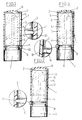
- Figure 1 shows an elevation view of a container of the type proposed by the invention, fitted with a closing cap adapted and secured in the manner shown in a vertical plane section.
- the complementary figure inside a circle, shows an enlarged detail of the container body and closing cap attachment system, revealing that both the container and the cap present respective annular projections which couple onto one another and hold both elements together when closed.
- Figure 2 is similar to the preceding figure, the complementary figure showing an enlarged detail of the attachment device in which the channel lodging the attaching projection is formed in the closing cap.
- Figure 3 shows an elevation view of a lipstick container fitted with a closing cap shown in a vertical plane section.
- This figure depicts an arrangement of the closing cap attachment over the container body, the lower zone of which has a peripheric channel into which fits the closing cap nerve or projection, which is thus retained over the container body.
- This attachment detail of the two bodies can be seen in the complementary enlarged figure showing the attachment device.
- number 1 generally identifies the container body; number 2, the external tubular body fitted with helicoidal channels; number 3, the grooved tubular body, concentric to the external body.
- Number 4 identifies the cap for holding the product bar 5; number 6, the container closing cap.
- Inner tubular body 3 has an extended lower end with a grooved zone 7, advantageously of a larger diameter, designed to facilitate the handling of said inner tubular body 3 when rotated for axial movement of cap 4 holding the product bar 5.
- Number 6 identifies the closing cap, with its open end 8 and closed opposite end 9.
- Number 10 identifies the annular projection or nerve projecting from the inner wall of the cap; number 11 is the peripheric nerve projecting along the container's inner part.
- Number 12 identifies the gap between the container body and the walls of cap 6.
- Number 13 identifies the attachment channel in cap 6; number 14 is the coinciding nerve or projection which, in this case, is formed in the container body.
- the improved mechanical container 1 proposed by the invention comprises, as these containers normally do, two concentric and mutually adapted cylindrical/ tubular elements 2, 3 inside of which is slidingly lodged a cap 4 that secures the product bar 5, said cap 4 being capable of alternate rectilinear motions drawing the lipstick 5 partially out of the container and back inside.
- the assembly thus forms a container body 1 fitted with appropriate mechanical means for alternatively operating the cap 4 holding the product bar 5.
- attachment means are provided between the container body 1 and the surrounding closing cap 6, the lipstick bar 5 remaining totally hidden and protected inside the container.
- the upper part of body 1 has a zone 7 formed by an extension, advantageously of a larger diameter, of the inner tubular element or reed 2 which, when rotated manually in either direction, draws the lipstick bar 5 outward or inward.
- tubular body 2 shows an increased thickness or nerve 11 which extends, uninterruptedly or otherwise, along the periphery of body 2, said nerve 11 acting as a retainer for the cap 6 when the latter is fitted and surrounds the upper part of container 1.
- Cap 6 which provides an upper cover for the container 1, is formed by a cylindrical tubular body with a closed upper end 9 and open opposite end 8 and reveals, along its inner plane and near the edge of its open end 8, an increased thickness or nerve with a curvilinear section 10 extending, either uninterruptedly or otherwise, along the inner wall of cap 6 and forming a ring 10, thereby providing three main functions: the first function of the cap's increased thickness or annular nerve 10 consists in cooperating with the peripheric nerve 11 projecting from the body of the container 1 in order to establish and secure, between the nerves 10 and 11, a perfect retainer for the cap 6 over the container body 1; the second function consists in forming an annular line having minimum contact with the external wall of the container, thus achieving a smooth sliding movement of the cap 6 over the container body 1; the third function consists in reinforcing the lower open edge 8 of cap 6 to prevent its tearing.
- the enlarged complementary detail in figure 2 reveals that the annular nerve 10 in cap 6, when applied over the container 1, forms a small gap 12 between the two bodies in such a manner that the sliding of the cap 6 over the container 1 is implemented by contacting only the fine annular line offered by the continuous or discontinuous nerve 10 in the cap 6.
- An extremely smooth sliding action of cap 6 is achieved via this major improvement along the whole length of the container 1 section forming the lipstick driving mechanism.
- annular nerve 10 Upon inserting the cap by simple manual pressure, annular nerve 10 contacts annular nerve 11 on the container body 1, undergoes a slight resilient radial deformation and surpasses said container nerve 11, thereby retaining and stabilizing the cap in the container's closed position.
- the container body cap is removed manually by sliding the cap nerve 10 over nerve 11 on the container 1, whereby it resiliently deforms and ceases the blocking to allow movement of the cap 6 to open the container.
- the invention also foresees the possibility that cap 6, on reaching the end of its run, opposes its nerve 10 to a coinciding channel 14 in the periphery of the container, becomes inserted in it and remains lodged in the closed position of container 1.
- This blocking is established because the cap's projection or annular nerve 10, upon pressing on the container body, develops a central perimetric pressure; when said annular projection 10 coincides with the channel 11, said pressure pushes it into the channel and stabilizes the cap in the closed position.
- the preceding description indicates that the annular nerve 10 is formed along the inner wall of cap 6 and the fitting channel or groove 11 is formed in the container body, as shown in Figure 3 of the drawings.
- This type of attachment is not the only one allowed, since the attachment can equally be implemented by forming the projection or nerve 14 on the body of the container and forming the attachment channel 13 receiving said nerve 14 along the inner wall of cap 6, as shown in Figure 2 in its enlarged detail.
Landscapes
- Closures For Containers (AREA)
- Packaging Of Annular Or Rod-Shaped Articles, Wearing Apparel, Cassettes, Or The Like (AREA)
Applications Claiming Priority (4)
| Application Number | Priority Date | Filing Date | Title |
|---|---|---|---|
| ES9700258U | 1997-02-03 | ||
| ES9700258U ES1036295Y (es) | 1997-02-03 | 1997-02-03 | Envase perfeccionado para productos en forma de barra. |
| ES9702752 | 1997-10-27 | ||
| ES9702752U ES1038509Y (es) | 1997-10-27 | 1997-10-27 | Envase perfeccionado para productos en forma de barra. |
Publications (2)
| Publication Number | Publication Date |
|---|---|
| EP0865743A2 true EP0865743A2 (de) | 1998-09-23 |
| EP0865743A3 EP0865743A3 (de) | 1999-10-27 |
Family
ID=26155036
Family Applications (1)
| Application Number | Title | Priority Date | Filing Date |
|---|---|---|---|
| EP98500016A Withdrawn EP0865743A3 (de) | 1997-02-03 | 1998-01-26 | Mechanischer Behälter für stiftförmige Produkte |
Country Status (1)
| Country | Link |
|---|---|
| EP (1) | EP0865743A3 (de) |
Cited By (4)
| Publication number | Priority date | Publication date | Assignee | Title |
|---|---|---|---|---|
| EP1078583A1 (de) * | 1999-08-23 | 2001-02-28 | Demellier Joulia SARL | Verbesserte Drehhülle |
| FR2869815A1 (fr) | 2004-05-07 | 2005-11-11 | Techpack Int Sa | Distributeur d'un produit pateux, typiquement d'un produit cosmetique pour le maquillage des levres |
| EP1647200A2 (de) | 2004-10-18 | 2006-04-19 | Techpack International | Kosmetikspender mit magnetischem Halter |
| DE202009003423U1 (de) | 2008-06-24 | 2009-05-20 | Alcan Packaging Beauty Services | Spender für Stiftprodukte |
Family Cites Families (7)
| Publication number | Priority date | Publication date | Assignee | Title |
|---|---|---|---|---|
| US2309000A (en) * | 1940-11-26 | 1943-01-19 | Morrison Simon | Rotary lipstick holder |
| US2360350A (en) * | 1942-10-10 | 1944-10-17 | Kirk-Schneider Hugo Montague | Cosmetic or like holder |
| US3416868A (en) * | 1966-04-20 | 1968-12-17 | Int Silver Co | Lipstick or the like container |
| US4098421A (en) * | 1977-06-24 | 1978-07-04 | J. L. Clark Manufacturing Co. | Container for snuff or the like |
| FR2662921B1 (fr) * | 1990-06-07 | 1992-09-04 | Oreal | Procede d'obtention d'un dispositif pour appliquer un produit pateux, et dispositif ainsi obtenu. |
| CN1066033C (zh) * | 1994-07-08 | 2001-05-23 | 株式会社希丹 | 一种化妆品容器 |
| JP2678571B2 (ja) * | 1994-07-08 | 1997-11-17 | 株式会社資生堂 | 棒状化粧料容器 |
-
1998
- 1998-01-26 EP EP98500016A patent/EP0865743A3/de not_active Withdrawn
Non-Patent Citations (1)
| Title |
|---|
| None |
Cited By (7)
| Publication number | Priority date | Publication date | Assignee | Title |
|---|---|---|---|---|
| EP1078583A1 (de) * | 1999-08-23 | 2001-02-28 | Demellier Joulia SARL | Verbesserte Drehhülle |
| FR2797754A1 (fr) * | 1999-08-23 | 2001-03-02 | Demellier Joulia | Perfectionnement pour etui tournant |
| US6513536B1 (en) | 1999-08-23 | 2003-02-04 | Demellier Joulia Sarl | Rotary holder |
| FR2869815A1 (fr) | 2004-05-07 | 2005-11-11 | Techpack Int Sa | Distributeur d'un produit pateux, typiquement d'un produit cosmetique pour le maquillage des levres |
| EP1647200A2 (de) | 2004-10-18 | 2006-04-19 | Techpack International | Kosmetikspender mit magnetischem Halter |
| FR2876555A1 (fr) | 2004-10-18 | 2006-04-21 | Techpack Int Sa | Distributeur d'un produit cosmetique a support magnetique |
| DE202009003423U1 (de) | 2008-06-24 | 2009-05-20 | Alcan Packaging Beauty Services | Spender für Stiftprodukte |
Also Published As
| Publication number | Publication date |
|---|---|
| EP0865743A3 (de) | 1999-10-27 |
Similar Documents
| Publication | Publication Date | Title |
|---|---|---|
| JP3772348B2 (ja) | 液体を順次分配するためのピペット | |
| EP1077086A3 (de) | Verschluss bestehend aus einem Stopfen und einer Schutzkappe | |
| EP0620988B1 (de) | Spender für Kosmetika mit langlebigem Drehwiderstand | |
| US4884912A (en) | Make-up applicator having a replaceable product cartridge | |
| US6484376B1 (en) | Jewelry safety clasp | |
| KR100287747B1 (ko) | 등산용및동굴탐사용카라비너 | |
| US20020159860A1 (en) | Spring-loaded and locking pin press | |
| US5152626A (en) | Writing pen with retractable clip | |
| KR100496245B1 (ko) | 봉형상 화장료 슬라이딩 용기 | |
| HU220546B1 (hu) | Állítószerkezet porszívó teleszkópos szívócsövéhez | |
| US5749664A (en) | Cosmetic container having an insert sleeve to improve air tightness and rotational characteristics | |
| EP0848915A3 (de) | Vorrichtung zur Befestigung einer schwenkbaren Visierscheibe an einem Helm | |
| EP1013195A3 (de) | Teleskoporgan, zylindrischer Körper und Formkörper | |
| KR960003637A (ko) | 화장품 용기 | |
| CZ43298A3 (cs) | Vodící součást pro sprchovou nástěnnou tyč | |
| EP0865743A2 (de) | Mechanischer Behälter für stiftförmige Produkte | |
| US6902333B2 (en) | Container capable of moving a contained article in longitudinal direction | |
| TW201936082A (zh) | 棒狀化妝料收納容器 | |
| US20040076461A1 (en) | Offset pen structure | |
| US20070102125A1 (en) | Sliding wheel unit for a blind | |
| US5899621A (en) | Lipstick swivel mechanism with brake function | |
| EP0799589A3 (de) | Lippenstifthülse mit Rückstossverhinderungseinrichtung | |
| JPH11513923A (ja) | 軟芯ペンシル | |
| USD434851S (en) | Indirect ophthalmoscopy lens straight retaining ring | |
| JPH0331232Y2 (de) |
Legal Events
| Date | Code | Title | Description |
|---|---|---|---|
| PUAI | Public reference made under article 153(3) epc to a published international application that has entered the european phase |
Free format text: ORIGINAL CODE: 0009012 |
|
| AK | Designated contracting states |
Kind code of ref document: A2 Designated state(s): AT BE CH DE FR GB GR IE IT LI LU NL |
|
| AX | Request for extension of the european patent |
Free format text: AL;LT;LV;MK;RO;SI |
|
| PUAL | Search report despatched |
Free format text: ORIGINAL CODE: 0009013 |
|
| AK | Designated contracting states |
Kind code of ref document: A3 Designated state(s): AT BE CH DE DK ES FI FR GB GR IE IT LI LU MC NL PT SE |
|
| AX | Request for extension of the european patent |
Free format text: AL;LT;LV;MK;RO;SI |
|
| 17P | Request for examination filed |
Effective date: 20000129 |
|
| AKX | Designation fees paid |
Free format text: AT BE CH DE FR GB GR IE IT LI LU NL |
|
| GRAH | Despatch of communication of intention to grant a patent |
Free format text: ORIGINAL CODE: EPIDOS IGRA |
|
| STAA | Information on the status of an ep patent application or granted ep patent |
Free format text: STATUS: THE APPLICATION IS DEEMED TO BE WITHDRAWN |
|
| 18D | Application deemed to be withdrawn |
Effective date: 20030114 |