EP0865799B1 - Ailettes de fixation réglables - Google Patents
Ailettes de fixation réglables Download PDFInfo
- Publication number
- EP0865799B1 EP0865799B1 EP97310619A EP97310619A EP0865799B1 EP 0865799 B1 EP0865799 B1 EP 0865799B1 EP 97310619 A EP97310619 A EP 97310619A EP 97310619 A EP97310619 A EP 97310619A EP 0865799 B1 EP0865799 B1 EP 0865799B1
- Authority
- EP
- European Patent Office
- Prior art keywords
- securing member
- catheter
- anchoring device
- body portion
- dilator
- Prior art date
- Legal status (The legal status is an assumption and is not a legal conclusion. Google has not performed a legal analysis and makes no representation as to the accuracy of the status listed.)
- Expired - Lifetime
Links
- 238000004873 anchoring Methods 0.000 claims description 72
- 239000000463 material Substances 0.000 claims description 9
- 230000013011 mating Effects 0.000 claims description 3
- 230000000916 dilatatory effect Effects 0.000 claims 1
- 239000013536 elastomeric material Substances 0.000 claims 1
- 238000001990 intravenous administration Methods 0.000 description 10
- 239000012530 fluid Substances 0.000 description 4
- 238000003780 insertion Methods 0.000 description 4
- 230000037431 insertion Effects 0.000 description 4
- 238000000034 method Methods 0.000 description 4
- 210000003462 vein Anatomy 0.000 description 4
- KJLPSBMDOIVXSN-UHFFFAOYSA-N 4-[4-[2-[4-(3,4-dicarboxyphenoxy)phenyl]propan-2-yl]phenoxy]phthalic acid Chemical compound C=1C=C(OC=2C=C(C(C(O)=O)=CC=2)C(O)=O)C=CC=1C(C)(C)C(C=C1)=CC=C1OC1=CC=C(C(O)=O)C(C(O)=O)=C1 KJLPSBMDOIVXSN-UHFFFAOYSA-N 0.000 description 3
- 210000003734 kidney Anatomy 0.000 description 3
- 230000002485 urinary effect Effects 0.000 description 3
- 241001631457 Cannula Species 0.000 description 2
- RRHGJUQNOFWUDK-UHFFFAOYSA-N Isoprene Chemical compound CC(=C)C=C RRHGJUQNOFWUDK-UHFFFAOYSA-N 0.000 description 2
- 230000000926 neurological effect Effects 0.000 description 2
- -1 polyethylene Polymers 0.000 description 2
- 229920002635 polyurethane Polymers 0.000 description 2
- 239000004814 polyurethane Substances 0.000 description 2
- 229920000915 polyvinyl chloride Polymers 0.000 description 2
- 239000004800 polyvinyl chloride Substances 0.000 description 2
- 210000002700 urine Anatomy 0.000 description 2
- 206010059484 Haemodilution Diseases 0.000 description 1
- 229920002633 Kraton (polymer) Polymers 0.000 description 1
- 239000004698 Polyethylene Substances 0.000 description 1
- 239000004743 Polypropylene Substances 0.000 description 1
- 229920006362 Teflon® Polymers 0.000 description 1
- 230000017531 blood circulation Effects 0.000 description 1
- 238000013461 design Methods 0.000 description 1
- 238000002347 injection Methods 0.000 description 1
- 239000007924 injection Substances 0.000 description 1
- 238000009434 installation Methods 0.000 description 1
- 239000004816 latex Substances 0.000 description 1
- 229920000126 latex Polymers 0.000 description 1
- 238000013508 migration Methods 0.000 description 1
- 230000005012 migration Effects 0.000 description 1
- 238000012986 modification Methods 0.000 description 1
- 230000004048 modification Effects 0.000 description 1
- 210000000056 organ Anatomy 0.000 description 1
- 239000004033 plastic Substances 0.000 description 1
- 229920003023 plastic Polymers 0.000 description 1
- 229920000573 polyethylene Polymers 0.000 description 1
- 229920001155 polypropylene Polymers 0.000 description 1
- 229920001296 polysiloxane Polymers 0.000 description 1
- 230000002787 reinforcement Effects 0.000 description 1
- 229920003031 santoprene Polymers 0.000 description 1
- 230000001988 toxicity Effects 0.000 description 1
- 231100000419 toxicity Toxicity 0.000 description 1
- 230000007704 transition Effects 0.000 description 1
- 230000000472 traumatic effect Effects 0.000 description 1
- 230000002792 vascular Effects 0.000 description 1
- 210000002620 vena cava superior Anatomy 0.000 description 1
Images


Classifications
-
- A—HUMAN NECESSITIES
- A61—MEDICAL OR VETERINARY SCIENCE; HYGIENE
- A61M—DEVICES FOR INTRODUCING MEDIA INTO, OR ONTO, THE BODY; DEVICES FOR TRANSDUCING BODY MEDIA OR FOR TAKING MEDIA FROM THE BODY; DEVICES FOR PRODUCING OR ENDING SLEEP OR STUPOR
- A61M25/00—Catheters; Hollow probes
- A61M25/01—Introducing, guiding, advancing, emplacing or holding catheters
- A61M25/02—Holding devices, e.g. on the body
-
- A—HUMAN NECESSITIES
- A61—MEDICAL OR VETERINARY SCIENCE; HYGIENE
- A61M—DEVICES FOR INTRODUCING MEDIA INTO, OR ONTO, THE BODY; DEVICES FOR TRANSDUCING BODY MEDIA OR FOR TAKING MEDIA FROM THE BODY; DEVICES FOR PRODUCING OR ENDING SLEEP OR STUPOR
- A61M25/00—Catheters; Hollow probes
- A61M25/01—Introducing, guiding, advancing, emplacing or holding catheters
- A61M25/02—Holding devices, e.g. on the body
- A61M2025/024—Holding devices, e.g. on the body having a clip or clamp system
-
- A—HUMAN NECESSITIES
- A61—MEDICAL OR VETERINARY SCIENCE; HYGIENE
- A61M—DEVICES FOR INTRODUCING MEDIA INTO, OR ONTO, THE BODY; DEVICES FOR TRANSDUCING BODY MEDIA OR FOR TAKING MEDIA FROM THE BODY; DEVICES FOR PRODUCING OR ENDING SLEEP OR STUPOR
- A61M25/00—Catheters; Hollow probes
- A61M25/01—Introducing, guiding, advancing, emplacing or holding catheters
- A61M25/02—Holding devices, e.g. on the body
- A61M2025/0286—Holding devices, e.g. on the body anchored in the skin by suture or other skin penetrating devices
-
- A—HUMAN NECESSITIES
- A61—MEDICAL OR VETERINARY SCIENCE; HYGIENE
- A61M—DEVICES FOR INTRODUCING MEDIA INTO, OR ONTO, THE BODY; DEVICES FOR TRANSDUCING BODY MEDIA OR FOR TAKING MEDIA FROM THE BODY; DEVICES FOR PRODUCING OR ENDING SLEEP OR STUPOR
- A61M25/00—Catheters; Hollow probes
- A61M25/0097—Catheters; Hollow probes characterised by the hub
-
- Y—GENERAL TAGGING OF NEW TECHNOLOGICAL DEVELOPMENTS; GENERAL TAGGING OF CROSS-SECTIONAL TECHNOLOGIES SPANNING OVER SEVERAL SECTIONS OF THE IPC; TECHNICAL SUBJECTS COVERED BY FORMER USPC CROSS-REFERENCE ART COLLECTIONS [XRACs] AND DIGESTS
- Y10—TECHNICAL SUBJECTS COVERED BY FORMER USPC
- Y10S—TECHNICAL SUBJECTS COVERED BY FORMER USPC CROSS-REFERENCE ART COLLECTIONS [XRACs] AND DIGESTS
- Y10S128/00—Surgery
- Y10S128/06—Intravenous injection support
-
- Y—GENERAL TAGGING OF NEW TECHNOLOGICAL DEVELOPMENTS; GENERAL TAGGING OF CROSS-SECTIONAL TECHNOLOGIES SPANNING OVER SEVERAL SECTIONS OF THE IPC; TECHNICAL SUBJECTS COVERED BY FORMER USPC CROSS-REFERENCE ART COLLECTIONS [XRACs] AND DIGESTS
- Y10—TECHNICAL SUBJECTS COVERED BY FORMER USPC
- Y10S—TECHNICAL SUBJECTS COVERED BY FORMER USPC CROSS-REFERENCE ART COLLECTIONS [XRACs] AND DIGESTS
- Y10S128/00—Surgery
- Y10S128/26—Cannula supporters
Definitions
- the invention relates to percutaneous catheters and more specifically to anchoring devices to secure percutaneous catheters at a desired location in a patient's body.
- Percutaneous catheters are commonly used in medical applications to deliver or remove fluids from a patient's body. It is very common in the treatment of patients to utilize intravenous catheters to introduce certain fluids directly into the bloodstream of the patients. It is also common to utilize catheterization to bypass blocked passage between organs. For example, when the passage between a kidney and the bladder is blocked, accepted treatment can be provided by catheterization of the kidney to drain urine.
- a catheter In general, a catheter consists of a soft tube, or cannula, having an opening, or lumen, extending through the cannula. Placing a catheter usually involves introducing an introducer sheath enveloped around a needle, the introducer sheath having an outside diameter slightly larger than the needle, into the patient at the desired location, and then removing the needle. The catheter is then introduced into the patient through the introducer. In the case of an intravenous catheter, the infused fluid flows directly through the catheter into the vein in which the catheter is introduced. In the case of a urinary drainage catheter, the urine is drained directly from the kidney to a dispensary.
- catheters also have different lengths.
- intravenous catheters for example, there exists several various lengths of catheters including short intravenous catheters that are placed peripherally, for example, in the hand, midline catheters that are fed approximately six to eight inches into a vein, for example, from the hand to the upper arm where the vein is bigger and better hemodilution and blood flow is achieved, and central venous catheters of significant length that may be placed peripherally, i.e., in the arm, and fed, for example, to the superior vena cava. Regardless of the length, it is desired to secure the catheter so that it maintains its position in the body.
- Catheter positioning in the patient's body is important, particularly in determining the concentration and toxicity of fluid added to the body.
- the catheter should be anchored to the exterior body of a patient, and ideally it should be anchored as closely as possible to the entry site or junction of the catheter to provide less opportunity for the catheter to be repositioned.
- Common securing devices include tape-down or lock-down wings fixedly attached to the catheter cannula.
- the fixed-location catheter lock-down wings work well if the full length of the catheter cannula is placed in the patient so that the wings are secured at the junction.
- a problem arises when the decision is made to shorten the placement of the catheter in the patient so that excess catheter material separates the lock-down wings from the introduction site or junction. If the wings are anchored to the patient at a position that is too far away from the insertion site, migration or pistoning of the catheter cannula can occur. One way to get around this is to cut the catheter cannula to length before insertion of the catheter into the body.
- catheter cannulas are generally constructed with a tapered tip at the introductory end to make insertion easier, i.e., less traumatic, to the patient. If the tapered tip is removed, for example by clipping a section of the catheter away, such patient considerations are ignored. Further, if the shortened estimate turns out to be incorrect, the physician or nurse still has excess catheter cannula material that must be dealt with. Another way to deal with the excess cannula material that extends from the junction, whether or not the catheter has been shortened, is to coil the excess catheter cannula material around the securing wings before the wings are secured to the patient. This method allows the securing device to be anchored at the junction, but creates an awkward and bulky device.
- Adjustable anchoring devices have been introduced that allow the device to be positioned at the catheter junction once the catheter is placed. However, these devices are either bulky or difficult to effectively install at the junction site.
- One adjustable anchoring device is a two-piece device wherein a flexible first piece with a split along its bottom portion fits over the cannula adjacent to the junction, and a second rigid piece snaps over the first piece to compress the first piece to the cannula so that the catheter device cannot move. The entire apparatus is then sutured or taped to the skin.
- a problem with this type of device is that it is a two-piece device that must be sized and fit on the catheter cannula at the junction. The placement of the securing device must be done in an artful manner so as not to disturb the patient or lose the distinct pieces. Further, the second rigid piece makes the device bulky.
- adjustable anchoring device compressing an eyelet, two-piece squeeze fit fastening device.
- This device utilizes at least one cylindrical eyelet that fits around the catheter and inside a two-piece fastening device mounted on the catheter cannula. When the fastening device is forced together, the eyelet is compressed to apply frictional pressure to the catheter.
- This securing device involves at least three pieces that may be easily misplaced and it is difficult to manipulate and install the fastening device at the junction.
- EP-A-0 247 590 discloses a catheter securing member comprising a cylindrical body having a slot therealong. Its disclosures form the basis for the preamble of claim 1 appended hereto.
- An adjustable anchoring device as defined in claim 1 to retain a catheter at a desired location inside a patient includes a securing member with a tubular body portion and an opening extending through the tubular body portion.
- the opening of the tubular body portion has a first dimension that is adapted to retain the catheter by frictionally engaging the catheter.
- the body portion is also dilatable to form an opening with a second dimension such that the securing member can slidably move about the catheter.
- the anchoring device is intended to secure any of the various types of catheters, including, but not limited to, vascular, neurological, and urinary drainage catheters.
- a dilator member to dilate the tubular body portion of the securing member from having an opening with the first dimension to an opening with the larger second dimension is also provided for the present invention.
- the dilator member includes a forward end that is adapted to detachably mate with the securing member through a portion of the opening of the securing member. The mating dilates the body portion of the securing member from an opening with the first dimension to an opening with the second dimension.
- the dilator member and the securing member are adapted to slidably move about the catheter to easily position the catheter at the desired location, e.g., the junction.
- the invention relates to an adjustable anchoring device to retain a catheter at a desired location inside a patient.
- the invention is described below with reference to the following drawings.
- numerous specific details are set forth such as specific materials, configurations, and catheter types. It will be obvious, however, to one skilled in the art that these specific details need not be employed to practice the invention. In other instances, well-known materials or methods have not been described in detail in order to avoid unnecessarily obscuring the invention.
- Figures 1-8 illustrate an embodiment of the anchoring device of the invention.
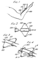
- Figure 1 illustrates the anchoring device of the invention to secure an intravenous catheter.
- the embodiment shown in Figures 1-8 may be used with any type of catheter, including, but not limited to, intravenous catheters, neurological catheters, and urinary drainage catheters.
- the invention relates to an adjustable anchoring device to retain a catheter at a desired location inside a patient.
- a catheter 100 is placed in a patient's arm 150 to a vein therein.
- the anchoring device of the invention is positioned directly next to the junction (i.e., the injection site).
- the anchoring device of the invention includes a securing member 110.
- the securing member 110 has a tubular body portion with an opening extending through the tubular body.
- the opening of the securing member 110 has a diameter sized to retain the catheter cannula 100 by frictionally engaging the catheter cannula 100 such that the securing member 110 is not movable about the catheter cannula 100. This is best illustrated in the perspective view of Figure 3 which illustrates the securing member 110 frictionally engaged to the catheter cannula 100.
- the diameter of the opening of the securing member 110 can also be sized slightly smaller than the catheter cannula 100 to impart a compressive force to the cannula 100, in addition to the frictional force.
- Figures 1 and 2 illustrate an anchoring device with a securing member 110 situated at a desired location adjacent the catheter hub 120.
- the anchoring device of the invention includes a dilator member 140.
- the dilator member 140 can slidably move about the catheter cannula 100.
- the dilator member 140 has an opening with a diameter larger than the catheter cannula 100.
- the dilator member 140 is adapted to mate with securing member 110 through a portion of the opening in the tubular body portion of securing member 110.
- Figure 4 illustrates a perspective view of the anchoring device of the invention about a catheter cannula 100.
- Figure 4 shows a securing member 110 with an opening that has been dilated by dilator member 140 so that securing member 110 does not frictionally engage the catheter cannula 100. Instead, the entire anchoring device assembly, including the dilator member portion 140 and the securing member portion 110, collectively define an opening of sufficient diameter to move the anchoring device about the catheter cannula 100.
- the dilator member 140 has a score or slice 145 running along its length to allow the dilator member 140 to be divided into two pieces to facilitate its removal from the catheter once the securing member 110 is in place.
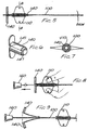
- Figure 5 illustrates a top, cross-sectional view of the anchoring device of the invention through lines A-A of Figure 4.
- Figure 5 shows a dilator member portion 140 that includes a tubular body portion having an opening extending through the body portion and a diameter of the opening greater than the outside diameter of the catheter cannula 100.
- FIG. 6 illustrates a perspective side view of the dilator member 140 of the invention.
- the dilator member 140 includes a substantially tubular body portion with an opening extending the length of the body portion.
- the body portion is made of a durable material like plastics such as polyurethane, polyethylene, TEFLON® (produced by E.I. DuPont de Nemours and Company, Wilmington, Delaware), polypropylene, and polyvinyl chloride.
- the body portion of the embodiment shown in Figure 6, includes a tapered portion 147 to ease insertion and mating with securing member 110.
- the dilator member 140 further includes a section of reduced wall thickness or scored (e.g., sliced with a blade) section 145 on opposing sides of the dilator member 140. The reduced thickness portions allow the dilator member to be divided into two pieces to remove the dilator member 140 from the catheter once the securing member 110 is in place.
- Figure 7 illustrates a cross-sectional view of the adjustable anchoring device of the invention taken through line B-B of Figure 5.
- the anchoring device includes a securing member 110 with an opening dilated by dilator member 140 to expand the opening of the anchoring device such that the anchoring device can freely move about the catheter cannula 100 and be adjusted at any desired location.
- the dilator member portion 140 is removed and the tubular body portion of the securing member 110 assumes a diameter that frictionally engages the catheter cannula 100.
- the opening in the tubular body portion of the securing member 110 is sized to frictionally engage the catheter cannula 100 so that the securing member 110 is not movable about the cannula 100.
- catheter cannulas of various sizes will have anchoring devices, including securing members with body portions of various diameters to securely engage the catheters by frictional gripping force.
- the opening in the tubular body portion may be sized slightly smaller than the outside diameter of the catheter cannula 100. In this manner, the securing member 110 compressively as well as frictionally engages the cannula 100.
- Suitable elastomeric materials for constructing the tubular body portion of the securing member so that it is dilatable but will return, in its non-dilated state, to frictionally or frictionally and compressively engage the catheter include, but are not limited to, silicone, polyurethane, latex, polyvinyl chloride, KRATON® (produced by Shell Oil Company, Houston, Texas), isoprene, SANTOPRENE® (produced by Monsanto Company, St. Louis, Missouri), and HYTREL® (produced by E.I. DuPont de Nemours, Wilmington, Delaware).
- Figures 8 and 9 illustrate the removal of the dilator member 140 from the securing member 110 once the securing member 110 is placed in the desired location on the catheter 100.
- Figure 8 demonstrates that the securing member 110 is held firmly in place by hand or other means, including sutures, tape, etc., and the dilator member 140 is advanced away from the securing member 110. Once the dilator member 140 is away from the securing member 110, the securing member 110 frictionally or frictionally and compressively engages the cannula 100. Also, while pulling the dilator member 140 away from the securing member 110, the dilator member is divided and peeled away from the catheter.
- FIGS 8 and 9 describe an embodiment wherein the dilator member 140 is removed from the catheter once the securing member 110 is properly placed.
- the invention contemplates also that the dilator member may remain on the catheter and used for catheter reinforcement or kink resistance or the like.
- Figures 10 and 11 illustrate different embodiments for the securing member portion of the anchoring device of the invention.
- Figure 10 illustrates a securing member 200 that includes a tubular body portion 210 that is curved.
- the curvature of the tubular body portion 210 of the securing member 200 provides additional gripping support to securely hold the catheter cannula and can also guide the catheter into a direction different than the direction the catheter enters the securing member 110.
- the invention contemplates that a dilator member is similarly shaped so as to dilate, if necessary, the entire curved body portion 210 of the securing member 200.
- Figure 11 illustrates an embodiment of the anchoring device with a securing member 250 including a tubular body portion 260 that is completely curved.
- a dilator member portion will dilate the entire curved body portion 260 of the securing member 250.
- Figure 12 illustrates another embodiment of the securing member portion of the invention.
- Figure 12 presents a securing member 300 with a pair of dilatible annularly shaped portions or rings 310 that surround the catheter cannula 100.
- a dilator member portion must dilate each securing wing 310.
- Figures 13 and 14 illustrate other embodiments of the securing member of the invention.
- Figures 13 and 14 present securing member portions wherein the securing device is a non-tubular section or sections.
- the securing member 320 of Figure 13 includes an arcuately-shaped or arched body 330 that engages a catheter cannula.
- the opening in the arch portion 330 frictionally or frictionally and compressively engages the cannula.
- Figure 14 illustrates a securing member 340 that includes a plurality, in this case, three, arcuately-shaped portions 350 that are each dilatible and that frictionally or frictionally and compressively engage the catheter cannula.
- Figure 15 illustrates a second embodiment of the dilator member portion of the anchoring device of the invention.
- the dilator member 360 has a split collar 370 to facilitate the division of the dilator member 360.
- opposing wings of the collar portion 370 are pulled apart while the dilator member 360 is separated from the securing member.
- the invention further contemplates that the securing member and optionally the dilator member are pre-loaded on the catheter body.
- the pre-loaded embodiment is particularly useful wherein the opening or openings in the securing member portion are sized slightly smaller than the catheter cannula.
- the pre-loaded embodiment also eliminates the possible misplacement of the components of the anchoring device and facilitates the simple installation of the anchoring device.
- the invention also contemplates an anchoring device that is not pre-loaded, but that is installed on the catheter once the catheter is placed in a patient. Further, because the dilator member is removed once the securing member is in place, the anchoring device of the invention is not bulky or cumbersome.
- FIGS 16-20 illustrate the anchoring device for use with an over-the-needle catheter.
- An over-the-needle catheter consists generally of a needle coupled to an extended stylet and a catheter cannula extending over the needle and the length of the stylet.
- the needle and catheter cannula are placed simultaneously, allowing the use of a smaller needle size, e.g., 3-4 gauges smaller, than a through-the-introducer type catheter where the catheter must enter through the opening created by the needle.
- the outside diameter of the catheter is greater than the opening made by the needle, thus allowing a similar diameter catheter to be inserted with a smaller needle.
- a problem associated with over-the-needle catheters is that it can be difficult to insert both the needle and the catheter cannula at the same time. Since the catheter moves freely over the needle and stylet, when the needle is inserted, the catheter may buckle or resist entry.
- One way to overcome this problem is through the use of deformable clamping wings which clamp or pinch the catheter and needle when the wings are folded together.
- Figures 16 and 17 illustrate an embodiment of the invention wherein the securing member 410 includes deformable wings that, when compressed or folded, clamp or pinch the catheter and needle or stylet.
- Figure 16 illustrates the securing member 410 with the wings in a down or unfolded position.
- Figure 17 illustrates the securing member 410 with wings in a folded or clamping position on the catheter cannula 400 and the needle 440 coupled to the stylet 450.
- the anchoring device of this embodiment works similarly to that described above with reference to Figures 1-15 including a securing member portion 410 and a dilator member 420 to dilate the body portion of the securing member 410.
- This embodiment adds the additional feature that the wings are deformable such that the securing member 410 may also clamp, by applying additional compressive force, the catheter cannula/needle as the cannula and needle are placed in a patient.
- Window 430 illustrates that the cannula and needle are squeezed by the securing device when the wings 410 are folded to impart additional compressive force. In an unfolded state, a non-dilated securing member 410 fixedly engages the cannula 400 as described above.
- Figures 18-20 illustrate a further embodiment of the invention, particularly useful with over-the-needle catheters.
- Dilator member 520 is forced into securing member 510 and dilates the tubular body portion of securing member 510 as described above with reference to Figures 4-8 and the accompanying text. Dilator member further extends beyond the securing member 510 and into the skin/body of the patient as shown in Figure 19.
- the dilator member 520 acts as an introducer allowing a smoother transition for placing the catheter cannula, e.g., the over-the-needle catheter, by freeing the passageway and eliminating any skin drag.
- Figure 20 illustrates that once the catheter is properly placed, the dilator member 520 may be removed from the skin/body and the securing member 510 and, optionally, removed from the catheter completely by division.
Landscapes
- Health & Medical Sciences (AREA)
- Life Sciences & Earth Sciences (AREA)
- Biophysics (AREA)
- Pulmonology (AREA)
- Engineering & Computer Science (AREA)
- Anesthesiology (AREA)
- Biomedical Technology (AREA)
- Heart & Thoracic Surgery (AREA)
- Hematology (AREA)
- Animal Behavior & Ethology (AREA)
- General Health & Medical Sciences (AREA)
- Public Health (AREA)
- Veterinary Medicine (AREA)
- Media Introduction/Drainage Providing Device (AREA)
Claims (18)
- Dispositif d'ancrage ajustable pour retenir un cathéter (100) à un emplacement désiré à l'intérieur d'un patient, le dispositif d'ancrage comprenant :ladite ouverture possédant une première dimension adaptée pour retenir ledit cathéter (100) en engageant par frottement ledit cathéter (100), et ladite partie de corps étant dilatable de telle sorte que l'ouverture possède une seconde dimension de telle sorte que ledit élément de fixation (110) puisse se déplacer de manière coulissante autour dudit cathéter (100) ; caractérisé en ce que :un élément de fixation (110) possédant une partie de corps ayant une ouverture s'étendant à travers ladite partie de corps,
le dispositif comprend en outre :un élément de dilatation (140) possédant une extrémité avant, dans lequel ladite extrémité avant est adaptée pour s'accoupler de manière détachable avec ledit élément de fixation (110) par le biais d'une portion de ladite ouverture dudit élément de fixation, dilatant ainsi ladite partie de corps dudit élément de fixation (110) afin qu'elle passe de l'ouverture ayant ladite première dimension à l'ouverture ayant ladite seconde dimension, l'élément de fixation étant déplaçable de manière coulissante autour du cathéter avec l'élément de dilatation accouplé avec l'élément de fixation. - Dispositif d'ancrage selon la revendication 1,
dans lequel ladite extrémité avant dudit élément de dilatation (140) comprend une partie de corps sensiblement tubulaire possédant une ouverture s'étendant dans la partie de corps dudit dilatateur, dans lequel ledit diamètre de ladite ouverture est supérieur audit diamètre extérieur dudit cathéter (100) de telle sorte que ledit dilatateur puisse se déplacer de manière coulissante autour dudit cathéter, et
dans lequel ledit corps tubulaire dudit élément de fixation (110) est dilaté afin d'avoir l'ouverture ayant ledit second diamètre par ladite partie de corps dudit dilatateur. - Dispositif d'ancrage selon la revendication 2, dans lequel ladite partie de corps dudit élément de dilatation (140) comprend une partie conique (147) afin de faciliter ledit accouplement dudit élément de dilatation (140) avec ledit élément de fixation (110).
- Dispositif d'ancrage selon la revendication 2, dans lequel ladite partie de corps tubulaire dudit élément de dilatation (140) est composée d'un matériau durable dans lequel ladite partie de corps tubulaire est adaptée pour être divisée en deux morceaux.
- Dispositif d'ancrage selon la revendication 4, dans lequel ladite partie de corps tubulaire possède l'une d'une section rainurée et d'une section tranchée (145) s'étendant sensiblement autour de ladite longueur de ladite partie de corps tubulaire.
- Dispositif d'ancrage selon la revendication 1, dans lequel ladite partie de corps dudit élément de fixation (110) est composée d'un matériau élastomérique dilatable.
- Dispositif d'ancrage selon la revendication 1, dans lequel ladite première dimension de ladite ouverture dudit élément de fixation (110) est inférieure audit diamètre extérieur dudit cathéter (100) de telle sorte que ledit élément de fixation (110) soit adapté pour retenir ledit cathéter en engageant de manière compressive ledit cathéter.
- Dispositif d'ancrage selon la revendication 1, dans lequel ledit élément de fixation (110) comprend en outre une partie d'ailette de fixation couplée à ladite partie de corps afin de fixer ledit élément de fixation (110) sur le corps extérieur d'un patient.
- Dispositif d'ancrage selon la revendication 8, dans lequel ladite partie d'ailette de fixation est intégralement formée avec ladite partie de corps dudit élément de fixation (110).
- Dispositif d'ancrage selon la revendication 1, dans lequel ladite partie de corps dudit élément de fixation comprend une portion de forme sensiblement tubulaire.
- Dispositif d'ancrage selon la revendication 10, dans lequel ladite partie de corps tubulaire dudit élément de fixation comprend une portion courbée (210).
- Dispositif d'ancrage selon la revendication 1, dans lequel ladite partie de corps dudit élément de fixation comprend une portion de forme sensiblement annulaire (310).
- Dispositif d'ancrage selon la revendication 1, dans lequel ladite partie de corps dudit élément de fixation comprend une pluralité de portions de forme sensiblement annulaire (310).
- Dispositif d'ancrage selon la revendication 1, dans lequel ladite partie de corps dudit élément de fixation comprend une portion de forme arquée (330).
- Dispositif d'ancrage selon la revendication 1, dans lequel ladite partie de corps dudit élément de fixation comprend une pluralité de portions de forme sensiblement arquée (350).
- Dispositif d'ancrage selon la revendication 1, dans lequel ledit élément de fixation comprend des portions d'ailettes de fixation déformables possédant une première position et une seconde position,
dans lequel, dans ladite première position et dans ladite ouverture de ladite partie de corps dudit élément de fixation possédant une seconde dimension, ledit dispositif d'ancrage est adapté pour engager par frottement ledit cathéter, et
dans lequel, dans ladite seconde position, ledit dispositif d'ancrage peut se déplacer de manière coulissante autour dudit cathéter. - Dispositif d'ancrage selon l'une quelconque des revendications précédentes, dans lequel ladite extrémité avant dudit élément de dilatation est adaptée pour être avancée dans une ouverture de cathéter dans un patient par extension au-delà de l'élément de fixation avec l'élément de dilatation accouplé avec l'élément de fixation.
- Kit de cathéter comprenant :un cathéter (100) à insérer dans un patient ; etun dispositif d'ancrage ajustable défini dans l'une quelconque des revendications précédentes.
Applications Claiming Priority (2)
| Application Number | Priority Date | Filing Date | Title |
|---|---|---|---|
| US08/773,975 US5814021A (en) | 1996-12-26 | 1996-12-26 | Adjustable securing wings |
| US773975 | 1996-12-26 |
Publications (3)
| Publication Number | Publication Date |
|---|---|
| EP0865799A2 EP0865799A2 (fr) | 1998-09-23 |
| EP0865799A3 EP0865799A3 (fr) | 1998-09-30 |
| EP0865799B1 true EP0865799B1 (fr) | 2004-07-28 |
Family
ID=25099875
Family Applications (1)
| Application Number | Title | Priority Date | Filing Date |
|---|---|---|---|
| EP97310619A Expired - Lifetime EP0865799B1 (fr) | 1996-12-26 | 1997-12-24 | Ailettes de fixation réglables |
Country Status (7)
| Country | Link |
|---|---|
| US (1) | US5814021A (fr) |
| EP (1) | EP0865799B1 (fr) |
| JP (1) | JP4152466B2 (fr) |
| AU (1) | AU725705B2 (fr) |
| CA (1) | CA2225580A1 (fr) |
| DE (1) | DE69730005T2 (fr) |
| ES (1) | ES2225939T3 (fr) |
Families Citing this family (36)
| Publication number | Priority date | Publication date | Assignee | Title |
|---|---|---|---|---|
| US6059801A (en) * | 1997-03-24 | 2000-05-09 | Samimi; Darius | Bladder saver retropubic ligature carrier device |
| US6889082B2 (en) | 1997-10-09 | 2005-05-03 | Orqis Medical Corporation | Implantable heart assist system and method of applying same |
| JP3342021B2 (ja) * | 1997-10-17 | 2002-11-05 | サーコン コーポレーション | 組織を貫通する医療機器システム |
| US6749588B1 (en) * | 1998-04-09 | 2004-06-15 | Becton Dickinson And Company | Catheter and introducer needle assembly with needle shield |
| US6332874B1 (en) | 1998-08-28 | 2001-12-25 | C.R. Bard, Inc. | Coupling and stabilization system for proximal end of catheter |
| US6139532A (en) * | 1998-09-15 | 2000-10-31 | Becton, Dickinson And Company | Clamping wing for catheter introducer |
| US7722539B2 (en) * | 1998-09-18 | 2010-05-25 | University Of Washington | Treatment of unwanted tissue by the selective destruction of vasculature providing nutrients to the tissue |
| US6270480B1 (en) * | 1998-10-05 | 2001-08-07 | Cancer Technologies, Inc. | Catheter apparatus and method |
| USD433503S (en) * | 1999-04-02 | 2000-11-07 | C. R. Bard, Inc. | Proximal end catheter coupling hub |
| US6488689B1 (en) | 1999-05-20 | 2002-12-03 | Aaron V. Kaplan | Methods and apparatus for transpericardial left atrial appendage closure |
| US6572587B2 (en) | 2000-01-10 | 2003-06-03 | Benjamin S. Lerman | Anchoring device for medical apparatus |
| US6471676B1 (en) | 2000-03-21 | 2002-10-29 | Novartis Nutrition Ag | Catheter and feeding tube retention device and method of use |
| US6761700B2 (en) * | 2001-02-09 | 2004-07-13 | Orqis Medical Corporation | Extra-corporeal vascular conduit |
| ATE294008T1 (de) * | 2001-10-23 | 2005-05-15 | Moynesign Ltd | Lagerklemme für katheter |
| US6960191B2 (en) * | 2002-12-10 | 2005-11-01 | Infusion Advancements, Llc | Over-the-needle safety midline catheter |
| USD498844S1 (en) | 2003-08-29 | 2004-11-23 | C. R. Bard, Inc. | Dual lumen catheter winged bifurcation |
| US8430852B2 (en) | 2007-04-17 | 2013-04-30 | Medtronic, Inc. | Therapeutic sleeve for implantable medical device |
| US8262624B2 (en) | 2008-03-27 | 2012-09-11 | Medtronic, Inc. | Anchor and anchor deployment apparatus |
| US8632502B2 (en) | 2008-03-27 | 2014-01-21 | Medtronic, Inc. | Anchor deployment apparatus |
| CA2775571C (fr) | 2009-10-06 | 2017-10-17 | Venetec International, Inc. | Dispositif de stabilisation comprenant une bague d'arret |
| US9700700B2 (en) | 2010-03-03 | 2017-07-11 | Venetec International, Inc. | Medical article with rotatable wings |
| US9550045B2 (en) | 2011-01-28 | 2017-01-24 | Medtronic, Inc. | Repositionable therapy delivery element anchor |
| USD655406S1 (en) * | 2011-03-07 | 2012-03-06 | Becton, Dickinson And Company | Vented flushable catheter assembly |
| US9962524B2 (en) | 2011-03-11 | 2018-05-08 | Venetec International, Inc. | Medical article securement device |
| US8483845B2 (en) | 2011-03-11 | 2013-07-09 | Greatbatch Ltd. | Anchor for implantable medical device |
| US8676341B2 (en) | 2011-06-21 | 2014-03-18 | Greatbatch Ltd. | Multi durometer reinforced suture sleeve |
| US8688232B2 (en) | 2011-06-21 | 2014-04-01 | Greatbatch Ltd. | Multi-durometer reinforced suture sleeve |
| US9669190B2 (en) | 2012-11-28 | 2017-06-06 | Cook Medical Technologies Llc | Selectively positionable catheter cuff |
| US9364639B2 (en) | 2013-03-15 | 2016-06-14 | Cook Medical Technologies Llc | Moveable cuff |
| EP3030311B1 (fr) | 2013-08-09 | 2018-01-03 | Medtronic Inc. | Déploiement de douille d'ancrage pour dispositifs médicaux implantables |
| WO2017042359A1 (fr) | 2015-09-09 | 2017-03-16 | B. Braun Melsungen Ag | Systèmes de perfusion, connecteurs pour une utilisation avec des dispositifs de cathéter, et procédés associés |
| US10569069B2 (en) | 2016-12-14 | 2020-02-25 | Combat Comb, Llc | Applicator for treatments applied to animal skin |
| USD828653S1 (en) * | 2016-12-14 | 2018-09-11 | Brandon Penland | Treatment applicator |
| US11786233B2 (en) * | 2020-03-27 | 2023-10-17 | Covidien Lp | Retention anchor with suture tie down for surgical access devices |
| CA3223151A1 (fr) * | 2021-06-30 | 2023-01-05 | Jason Andrew Wine | Ancrage de tube |
| US20230211071A1 (en) * | 2021-12-30 | 2023-07-06 | Carefusion 303, Inc. | Anchorable medical fluid extension set system |
Family Cites Families (22)
| Publication number | Priority date | Publication date | Assignee | Title |
|---|---|---|---|---|
| US3537451A (en) * | 1966-10-26 | 1970-11-03 | Deseret Pharma | Intravenous catheter unit with releasable inserter means |
| US4177809A (en) * | 1977-09-15 | 1979-12-11 | Warner-Lambert Company | Intravenous catheter apparatus and method |
| US4170995A (en) * | 1977-11-21 | 1979-10-16 | Levine Robert A | Catheter clamp |
| US4192304A (en) * | 1978-03-14 | 1980-03-11 | Johnson & Johnson | Intravenous catheter assembly with fluid flow restriction capability |
| US4419094A (en) * | 1981-06-08 | 1983-12-06 | The Kendall Company | Suprapubic catheter system |
| US4449975A (en) * | 1981-11-09 | 1984-05-22 | Perry Michael K | Intravenous anchor and wound shield |
| SE445709B (sv) * | 1983-02-15 | 1986-07-14 | Bengt Gustavsson | Anordning for fixering av katetrar, drenageror, slangar och liknande till huden |
| US4585443A (en) * | 1983-10-21 | 1986-04-29 | Hemedix International, Inc. | Catheter locating device |
| JPH0337638Y2 (fr) * | 1985-12-09 | 1991-08-08 | ||
| JPS62281965A (ja) * | 1986-05-29 | 1987-12-07 | テルモ株式会社 | カテ−テルおよびカテ−テル用固定部材 |
| US4869719A (en) * | 1986-10-20 | 1989-09-26 | City Of Hope | Anchoring mechanism for an adjustable length percutaneous drainage catheter |
| US4792330A (en) * | 1987-07-13 | 1988-12-20 | Lazarus Medical Innovations, Inc. | Combination catheter and duct clamp apparatus and method |
| US5084026A (en) * | 1989-07-14 | 1992-01-28 | Shapiro Robert A | Intravenous apparatus holder |
| US5192273A (en) * | 1989-07-24 | 1993-03-09 | Steven F. Bierman | Catheterization system |
| US5314411A (en) * | 1989-07-24 | 1994-05-24 | Steven F. Bierman, M.D. | Catheterization system with universal retention device and method of use |
| US4995872A (en) * | 1989-10-04 | 1991-02-26 | Ferrara Janice J | Expandable catheter and bridge device |
| US5215530A (en) * | 1991-07-11 | 1993-06-01 | City Of Hope | Sleeved extension and anchoring system for percutaneous catheters |
| US5242431A (en) * | 1992-06-11 | 1993-09-07 | Siemens Pacesetter, Inc. | Suture sleeve assembly with slidable compression collar |
| US5484420A (en) * | 1992-07-09 | 1996-01-16 | Wilson-Cook Medical Inc. | Retention bolsters for percutaneous catheters |
| US5292312A (en) * | 1993-01-08 | 1994-03-08 | Struckmeyer Corporation | Universal tube lumen catheter holder |
| GB2274783B (en) * | 1993-02-03 | 1996-12-11 | Graham Cameron Grant | Intravenous infusion set with needle protection |
| US5674201A (en) * | 1995-03-16 | 1997-10-07 | Becton Dickinson And Company | Rotatable catheter housed within a flexible wing assembly |
-
1996
- 1996-12-26 US US08/773,975 patent/US5814021A/en not_active Expired - Lifetime
-
1997
- 1997-12-23 AU AU49235/97A patent/AU725705B2/en not_active Ceased
- 1997-12-23 CA CA002225580A patent/CA2225580A1/fr not_active Abandoned
- 1997-12-24 EP EP97310619A patent/EP0865799B1/fr not_active Expired - Lifetime
- 1997-12-24 ES ES97310619T patent/ES2225939T3/es not_active Expired - Lifetime
- 1997-12-24 DE DE69730005T patent/DE69730005T2/de not_active Expired - Fee Related
- 1997-12-26 JP JP36884997A patent/JP4152466B2/ja not_active Expired - Fee Related
Also Published As
| Publication number | Publication date |
|---|---|
| AU725705B2 (en) | 2000-10-19 |
| US5814021A (en) | 1998-09-29 |
| AU4923597A (en) | 1998-07-02 |
| DE69730005D1 (de) | 2004-09-02 |
| JPH10234859A (ja) | 1998-09-08 |
| EP0865799A2 (fr) | 1998-09-23 |
| CA2225580A1 (fr) | 1998-06-26 |
| JP4152466B2 (ja) | 2008-09-17 |
| EP0865799A3 (fr) | 1998-09-30 |
| DE69730005T2 (de) | 2005-07-21 |
| ES2225939T3 (es) | 2005-03-16 |
Similar Documents
| Publication | Publication Date | Title |
|---|---|---|
| EP0865799B1 (fr) | Ailettes de fixation réglables | |
| US11504499B2 (en) | Catheter insertion apparatus | |
| EP0570530B1 (fr) | Catheter avec possibilite de modifier le nombre de passages | |
| US5382238A (en) | Catheter stiffeners | |
| EP0471429B1 (fr) | Cathéter à drainage | |
| US6645178B1 (en) | Apparatus for inserting medical device | |
| US4114618A (en) | Catheter assembly | |
| EP1028775B1 (fr) | Dispositif d'introduction médical comprenant un fourreau à extrémité evasée | |
| CA1319073C (fr) | Fourreau protecteur pour assemblage de catheter | |
| US4650472A (en) | Apparatus and method for effecting percutaneous catheterization of a blood vessel using a small gauge introducer needle | |
| EP0609020B1 (fr) | Moyen de rétention pour cathéter | |
| EP2077775B1 (fr) | Adaptateur pour tunnelisation de cathéter et procédé d'assemblage avec un cathéter | |
| US5419764A (en) | Percutaneous twisting lock catheter | |
| EP2491283B1 (fr) | Ensemble verrouillage pour cathéter de drainage | |
| US8979744B2 (en) | Tunneling system | |
| US20090118701A1 (en) | Methods and apparatus for inserting multi-lumen split-tip catheters into a blood vessel | |
| JP2003525093A (ja) | 医療用導入装置 | |
| WO2004026366A2 (fr) | Appareil et procede permettant de tunneliser de maniere inverse un catheter multi-lumiere dans une veine de patient | |
| EP1883441A1 (fr) | Ensemble catheter port pour traitement extracorporel | |
| CN222218403U (zh) | 可快速插入式中心导管插入组件和导引器针子组件 | |
| US4897077A (en) | Method of inserting an IAB device into the body | |
| US5735828A (en) | Method and device for catheterization | |
| JPH0442949B2 (fr) | ||
| WO1993004726A1 (fr) | Appareil de positionnement d'un catheter | |
| MXPA98000266A (en) | Adjustab fixing wings |
Legal Events
| Date | Code | Title | Description |
|---|---|---|---|
| PUAI | Public reference made under article 153(3) epc to a published international application that has entered the european phase |
Free format text: ORIGINAL CODE: 0009012 |
|
| PUAL | Search report despatched |
Free format text: ORIGINAL CODE: 0009013 |
|
| AK | Designated contracting states |
Kind code of ref document: A2 Designated state(s): BE CH DE ES FR GB IT LI SE |
|
| AX | Request for extension of the european patent |
Free format text: AL;LT;LV;MK;RO;SI |
|
| AK | Designated contracting states |
Kind code of ref document: A3 Designated state(s): AT BE CH DE DK ES FI FR GB GR IE IT LI LU MC NL PT SE |
|
| AX | Request for extension of the european patent |
Free format text: AL;LT;LV;MK;RO;SI |
|
| 17P | Request for examination filed |
Effective date: 19990310 |
|
| AKX | Designation fees paid |
Free format text: BE CH DE ES FR GB IT LI SE |
|
| 17Q | First examination report despatched |
Effective date: 20020829 |
|
| GRAP | Despatch of communication of intention to grant a patent |
Free format text: ORIGINAL CODE: EPIDOSNIGR1 |
|
| GRAS | Grant fee paid |
Free format text: ORIGINAL CODE: EPIDOSNIGR3 |
|
| GRAA | (expected) grant |
Free format text: ORIGINAL CODE: 0009210 |
|
| AK | Designated contracting states |
Kind code of ref document: B1 Designated state(s): BE CH DE ES FR GB IT LI SE |
|
| REG | Reference to a national code |
Ref country code: GB Ref legal event code: FG4D |
|
| REG | Reference to a national code |
Ref country code: CH Ref legal event code: EP |
|
| REF | Corresponds to: |
Ref document number: 69730005 Country of ref document: DE Date of ref document: 20040902 Kind code of ref document: P |
|
| REG | Reference to a national code |
Ref country code: SE Ref legal event code: TRGR |
|
| REG | Reference to a national code |
Ref country code: ES Ref legal event code: FG2A Ref document number: 2225939 Country of ref document: ES Kind code of ref document: T3 |
|
| ET | Fr: translation filed | ||
| PLBE | No opposition filed within time limit |
Free format text: ORIGINAL CODE: 0009261 |
|
| STAA | Information on the status of an ep patent application or granted ep patent |
Free format text: STATUS: NO OPPOSITION FILED WITHIN TIME LIMIT |
|
| 26N | No opposition filed |
Effective date: 20050429 |
|
| REG | Reference to a national code |
Ref country code: CH Ref legal event code: PFA Owner name: JOHNSON & JOHNSON MEDICAL, INC. Free format text: JOHNSON & JOHNSON MEDICAL, INC.#2500 ARBROOK BOULEVARD#ARLINGTON, TEXAS 76004-3030 (US) -TRANSFER TO- JOHNSON & JOHNSON MEDICAL, INC.#2500 ARBROOK BOULEVARD#ARLINGTON, TEXAS 76004-3030 (US) |
|
| PGFP | Annual fee paid to national office [announced via postgrant information from national office to epo] |
Ref country code: CH Payment date: 20081230 Year of fee payment: 12 |
|
| PGFP | Annual fee paid to national office [announced via postgrant information from national office to epo] |
Ref country code: SE Payment date: 20081205 Year of fee payment: 12 Ref country code: IT Payment date: 20081224 Year of fee payment: 12 |
|
| PGFP | Annual fee paid to national office [announced via postgrant information from national office to epo] |
Ref country code: FR Payment date: 20081212 Year of fee payment: 12 Ref country code: ES Payment date: 20090120 Year of fee payment: 12 |
|
| PGFP | Annual fee paid to national office [announced via postgrant information from national office to epo] |
Ref country code: DE Payment date: 20081219 Year of fee payment: 12 |
|
| PGFP | Annual fee paid to national office [announced via postgrant information from national office to epo] |
Ref country code: GB Payment date: 20081224 Year of fee payment: 12 |
|
| PGFP | Annual fee paid to national office [announced via postgrant information from national office to epo] |
Ref country code: BE Payment date: 20090119 Year of fee payment: 12 |
|
| BERE | Be: lapsed |
Owner name: *JOHNSON & JOHNSON MEDICAL INC. Effective date: 20091231 |
|
| EUG | Se: european patent has lapsed | ||
| REG | Reference to a national code |
Ref country code: CH Ref legal event code: PL |
|
| GBPC | Gb: european patent ceased through non-payment of renewal fee |
Effective date: 20091224 |
|
| REG | Reference to a national code |
Ref country code: FR Ref legal event code: ST Effective date: 20100831 |
|
| PG25 | Lapsed in a contracting state [announced via postgrant information from national office to epo] |
Ref country code: LI Free format text: LAPSE BECAUSE OF NON-PAYMENT OF DUE FEES Effective date: 20091231 Ref country code: FR Free format text: LAPSE BECAUSE OF NON-PAYMENT OF DUE FEES Effective date: 20091231 Ref country code: CH Free format text: LAPSE BECAUSE OF NON-PAYMENT OF DUE FEES Effective date: 20091231 Ref country code: BE Free format text: LAPSE BECAUSE OF NON-PAYMENT OF DUE FEES Effective date: 20091231 |
|
| PG25 | Lapsed in a contracting state [announced via postgrant information from national office to epo] |
Ref country code: DE Free format text: LAPSE BECAUSE OF NON-PAYMENT OF DUE FEES Effective date: 20100701 |
|
| PG25 | Lapsed in a contracting state [announced via postgrant information from national office to epo] |
Ref country code: GB Free format text: LAPSE BECAUSE OF NON-PAYMENT OF DUE FEES Effective date: 20091224 |
|
| REG | Reference to a national code |
Ref country code: ES Ref legal event code: FD2A Effective date: 20110310 |
|
| PG25 | Lapsed in a contracting state [announced via postgrant information from national office to epo] |
Ref country code: IT Free format text: LAPSE BECAUSE OF NON-PAYMENT OF DUE FEES Effective date: 20091224 |
|
| PG25 | Lapsed in a contracting state [announced via postgrant information from national office to epo] |
Ref country code: SE Free format text: LAPSE BECAUSE OF NON-PAYMENT OF DUE FEES Effective date: 20091225 |
|
| PG25 | Lapsed in a contracting state [announced via postgrant information from national office to epo] |
Ref country code: ES Free format text: LAPSE BECAUSE OF NON-PAYMENT OF DUE FEES Effective date: 20110309 |
|
| PG25 | Lapsed in a contracting state [announced via postgrant information from national office to epo] |
Ref country code: ES Free format text: LAPSE BECAUSE OF NON-PAYMENT OF DUE FEES Effective date: 20091225 |