EP0865863A1 - Bifokussierung-Optik-Kopf - Google Patents
Bifokussierung-Optik-Kopf Download PDFInfo
- Publication number
- EP0865863A1 EP0865863A1 EP97400618A EP97400618A EP0865863A1 EP 0865863 A1 EP0865863 A1 EP 0865863A1 EP 97400618 A EP97400618 A EP 97400618A EP 97400618 A EP97400618 A EP 97400618A EP 0865863 A1 EP0865863 A1 EP 0865863A1
- Authority
- EP
- European Patent Office
- Prior art keywords
- parts
- points
- gives
- cut
- relative translation
- Prior art date
- Legal status (The legal status is an assumption and is not a legal conclusion. Google has not performed a legal analysis and makes no representation as to the accuracy of the status listed.)
- Withdrawn
Links
Images

Classifications
-
- B—PERFORMING OPERATIONS; TRANSPORTING
- B23—MACHINE TOOLS; METAL-WORKING NOT OTHERWISE PROVIDED FOR
- B23K—SOLDERING OR UNSOLDERING; WELDING; CLADDING OR PLATING BY SOLDERING OR WELDING; CUTTING BY APPLYING HEAT LOCALLY, e.g. FLAME CUTTING; WORKING BY LASER BEAM
- B23K26/00—Working by laser beam, e.g. welding, cutting or boring
- B23K26/02—Positioning or observing the workpiece, e.g. with respect to the point of impact; Aligning, aiming or focusing the laser beam
- B23K26/06—Shaping the laser beam, e.g. by masks or multi-focusing
- B23K26/0604—Shaping the laser beam, e.g. by masks or multi-focusing by a combination of beams
- B23K26/0608—Shaping the laser beam, e.g. by masks or multi-focusing by a combination of beams in the same heat affected zone [HAZ]
-
- B—PERFORMING OPERATIONS; TRANSPORTING
- B23—MACHINE TOOLS; METAL-WORKING NOT OTHERWISE PROVIDED FOR
- B23K—SOLDERING OR UNSOLDERING; WELDING; CLADDING OR PLATING BY SOLDERING OR WELDING; CUTTING BY APPLYING HEAT LOCALLY, e.g. FLAME CUTTING; WORKING BY LASER BEAM
- B23K26/00—Working by laser beam, e.g. welding, cutting or boring
- B23K26/02—Positioning or observing the workpiece, e.g. with respect to the point of impact; Aligning, aiming or focusing the laser beam
- B23K26/06—Shaping the laser beam, e.g. by masks or multi-focusing
- B23K26/0604—Shaping the laser beam, e.g. by masks or multi-focusing by a combination of beams
-
- B—PERFORMING OPERATIONS; TRANSPORTING
- B23—MACHINE TOOLS; METAL-WORKING NOT OTHERWISE PROVIDED FOR
- B23K—SOLDERING OR UNSOLDERING; WELDING; CLADDING OR PLATING BY SOLDERING OR WELDING; CUTTING BY APPLYING HEAT LOCALLY, e.g. FLAME CUTTING; WORKING BY LASER BEAM
- B23K26/00—Working by laser beam, e.g. welding, cutting or boring
- B23K26/02—Positioning or observing the workpiece, e.g. with respect to the point of impact; Aligning, aiming or focusing the laser beam
- B23K26/06—Shaping the laser beam, e.g. by masks or multi-focusing
- B23K26/067—Dividing the beam into multiple beams, e.g. multi-focusing
Definitions
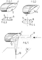
- the principle is based on the fact that a beam of light which arrives parallel to the axis of the optical device is focused at a point on this axis and if the optical devices FIGURES 1,2,3, and 4 are produced according to the invention in two parts, each part, in its section plane, comprises a half optical axis.
- the device relating to the invention has a single optical axis, as shown by way of example in FIGURE 5 .
- the device according to the invention has two distinct optical axes, as shown by way of example in FIGS. 6 and 7 .
- FIGURE 5 parabolic mirror As an example of a device according to the invention, let us consider a FIGURE 5 parabolic mirror as the mirror of FIGURE 1 with an incident laser beam (9), the two parts (1) and (2) not being offset relative to each other, the incident beam (9) is focused at a single point (10) in the plane (P).
- the device according to the invention also allows, by leaving fixed in the plane (P) the position of the two focal points (11) and (12) FIGURE 6 , to make a relative distribution of the light power between a focal point and the other, by moving the laser beam perpendicular to the plane of separation of the two parts (1) and (2) FIGURE 5 , in the direction (15).
- the incident laser beam at mirror has a power of 1000 W
- this configuration will be used in welding parts to plan thickness and / or metallurgical characteristics different.
- Another advantage of the device according to the invention is to be able to increase the depth of field by almost constant numerical aperture focusing for increase for example the depth of welding, cutting or drilling.
- FIGURE 7 focusing mirror, comparable to that of FIGURE 2 which, compared to the previous example, has a plane of separation of the two parts which is rotated by 90 °, that is to say say it is contained in the incidence plan.
- the device according to the invention has its two parts (3) and (4) whose optical axis of one is superimposed on that of the other.
- the part (3) shifts from the part (4) the two optical axes slide one on the other and the single focal point gives way to two separate focal points, one (14) below on the other (13).
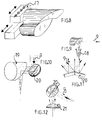
- the cut mirror (20) has its two half-surfaces reflecting in the same plane, the mirror of focusing (19) will give a single focal point.
- the cut mirror (20) has its two reflecting half-surfaces which are not contained in the same plane and form a dihedral whose edge is contained in their plane of separation of the two parts FIGURE 11 , the focusing mirror (19 ) will give the laser beam two focal points.
- FIGURE 12 shows by way of example the device, the focusing mirror of which has been replaced by a lens (21).
- FIGURES 10, 11 and 12 will only be applied in a limited number of cases because it induces some optical aberrations.
Landscapes
- Physics & Mathematics (AREA)
- Optics & Photonics (AREA)
- Engineering & Computer Science (AREA)
- Plasma & Fusion (AREA)
- Mechanical Engineering (AREA)
- Laser Beam Processing (AREA)
Priority Applications (1)
| Application Number | Priority Date | Filing Date | Title |
|---|---|---|---|
| EP97400618A EP0865863A1 (de) | 1997-03-19 | 1997-03-19 | Bifokussierung-Optik-Kopf |
Applications Claiming Priority (1)
| Application Number | Priority Date | Filing Date | Title |
|---|---|---|---|
| EP97400618A EP0865863A1 (de) | 1997-03-19 | 1997-03-19 | Bifokussierung-Optik-Kopf |
Publications (1)
| Publication Number | Publication Date |
|---|---|
| EP0865863A1 true EP0865863A1 (de) | 1998-09-23 |
Family
ID=8229728
Family Applications (1)
| Application Number | Title | Priority Date | Filing Date |
|---|---|---|---|
| EP97400618A Withdrawn EP0865863A1 (de) | 1997-03-19 | 1997-03-19 | Bifokussierung-Optik-Kopf |
Country Status (1)
| Country | Link |
|---|---|
| EP (1) | EP0865863A1 (de) |
Cited By (8)
| Publication number | Priority date | Publication date | Assignee | Title |
|---|---|---|---|---|
| US6531676B2 (en) * | 2000-01-22 | 2003-03-11 | Robert Bosch Gmbh | Method for producing an electrically conductive connection by laser radiation |
| FR2830477A1 (fr) * | 2001-10-09 | 2003-04-11 | Usinor | Procede et dispositif de soudage par recouvrement a l'aide d'un faisceau a haute densite d'energie de deux toles revetues |
| EP1491279A1 (de) * | 2003-06-27 | 2004-12-29 | Schuler Held Lasertechnik GmbH & Co. KG | Multifokales Schweissverfahren und Schweisseinrichtung |
| EP1524096A3 (de) * | 2003-10-14 | 2008-03-19 | Denso Corporation | Kunststoffgegenstand und Verfahren zu seiner Herstellung |
| WO2009132764A1 (de) * | 2008-05-02 | 2009-11-05 | Trumpf Laser- Und Systemtechnik Gmbh | Verfahren zum laserbearbeiten von werkstücken mittels einem laserstrahl und einer dynamischen strahlumlenkung dieses laserstrahls |
| WO2012007326A3 (de) * | 2010-07-15 | 2012-06-21 | Robert Bosch Gmbh | Bauelement für ein einspritzventil mit zwei verbundenen bauteilen und verfahren zur herstellung des bauelements |
| EP2774713A1 (de) * | 2013-03-07 | 2014-09-10 | Siemens Aktiengesellschaft | Laserverfahren mit unterschiedlichen Laserstrahlbereichen innerhalb eines Strahls und Vorrichtungen |
| CN113001015A (zh) * | 2021-03-25 | 2021-06-22 | 连云港倍特超微粉有限公司 | 一种基于双焦点反射镜的厚金属板激光焊接头及焊接方法 |
Citations (12)
| Publication number | Priority date | Publication date | Assignee | Title |
|---|---|---|---|---|
| EP0098048A1 (de) * | 1982-06-25 | 1984-01-11 | Philip Morris Incorporated | Strahlteiler |
| US4469931A (en) * | 1982-09-13 | 1984-09-04 | Macken John A | Laser assisted saw device |
| JPS6188989A (ja) * | 1984-10-05 | 1986-05-07 | Dowa Koei Kk | レ−ザ−ビ−ムによる突き合わせ溶接法 |
| US4691093A (en) * | 1986-04-22 | 1987-09-01 | United Technologies Corporation | Twin spot laser welding |
| JPH01143785A (ja) * | 1987-11-30 | 1989-06-06 | Mitsubishi Heavy Ind Ltd | 異軸多焦点式レーザビーム集光装置 |
| US5055653A (en) * | 1989-05-08 | 1991-10-08 | Matsushita Electric Industrial Co., Ltd. | Laser beam machining device |
| DE4024299A1 (de) * | 1990-07-31 | 1992-02-06 | Fraunhofer Ges Forschung | Vorrichtung zum fokussieren eines lichtstrahles in wenigstens zwei fokuspunkten |
| JPH04182087A (ja) * | 1990-11-17 | 1992-06-29 | Kobe Steel Ltd | レーザ加工用集光装置 |
| US5155323A (en) * | 1991-05-16 | 1992-10-13 | John Macken | Dual focus laser welding |
| JPH05138385A (ja) * | 1991-11-14 | 1993-06-01 | Toshiba Corp | レーザ加工方法及びその装置 |
| US5229572A (en) * | 1991-04-24 | 1993-07-20 | Brother Kogyo Kabushiki Kaisha | Laser processing apparatus having plural processing nozzles |
| EP0706072A2 (de) * | 1994-10-07 | 1996-04-10 | Sumitomo Electric Industries, Ltd. | Optische Einrichtung zur Werkstoffbearbeitung mittels Laser |
-
1997
- 1997-03-19 EP EP97400618A patent/EP0865863A1/de not_active Withdrawn
Patent Citations (12)
| Publication number | Priority date | Publication date | Assignee | Title |
|---|---|---|---|---|
| EP0098048A1 (de) * | 1982-06-25 | 1984-01-11 | Philip Morris Incorporated | Strahlteiler |
| US4469931A (en) * | 1982-09-13 | 1984-09-04 | Macken John A | Laser assisted saw device |
| JPS6188989A (ja) * | 1984-10-05 | 1986-05-07 | Dowa Koei Kk | レ−ザ−ビ−ムによる突き合わせ溶接法 |
| US4691093A (en) * | 1986-04-22 | 1987-09-01 | United Technologies Corporation | Twin spot laser welding |
| JPH01143785A (ja) * | 1987-11-30 | 1989-06-06 | Mitsubishi Heavy Ind Ltd | 異軸多焦点式レーザビーム集光装置 |
| US5055653A (en) * | 1989-05-08 | 1991-10-08 | Matsushita Electric Industrial Co., Ltd. | Laser beam machining device |
| DE4024299A1 (de) * | 1990-07-31 | 1992-02-06 | Fraunhofer Ges Forschung | Vorrichtung zum fokussieren eines lichtstrahles in wenigstens zwei fokuspunkten |
| JPH04182087A (ja) * | 1990-11-17 | 1992-06-29 | Kobe Steel Ltd | レーザ加工用集光装置 |
| US5229572A (en) * | 1991-04-24 | 1993-07-20 | Brother Kogyo Kabushiki Kaisha | Laser processing apparatus having plural processing nozzles |
| US5155323A (en) * | 1991-05-16 | 1992-10-13 | John Macken | Dual focus laser welding |
| JPH05138385A (ja) * | 1991-11-14 | 1993-06-01 | Toshiba Corp | レーザ加工方法及びその装置 |
| EP0706072A2 (de) * | 1994-10-07 | 1996-04-10 | Sumitomo Electric Industries, Ltd. | Optische Einrichtung zur Werkstoffbearbeitung mittels Laser |
Non-Patent Citations (4)
| Title |
|---|
| PATENT ABSTRACTS OF JAPAN vol. 010, no. 265 (M - 515) 10 September 1986 (1986-09-10) * |
| PATENT ABSTRACTS OF JAPAN vol. 013, no. 400 (M - 867) 6 September 1989 (1989-09-06) * |
| PATENT ABSTRACTS OF JAPAN vol. 016, no. 494 (M - 1324) 13 October 1992 (1992-10-13) * |
| PATENT ABSTRACTS OF JAPAN vol. 017, no. 520 (M - 1482) 20 September 1993 (1993-09-20) * |
Cited By (17)
| Publication number | Priority date | Publication date | Assignee | Title |
|---|---|---|---|---|
| US6531676B2 (en) * | 2000-01-22 | 2003-03-11 | Robert Bosch Gmbh | Method for producing an electrically conductive connection by laser radiation |
| FR2830477A1 (fr) * | 2001-10-09 | 2003-04-11 | Usinor | Procede et dispositif de soudage par recouvrement a l'aide d'un faisceau a haute densite d'energie de deux toles revetues |
| WO2003031111A1 (fr) * | 2001-10-09 | 2003-04-17 | Usinor | Procede et dispositif de soudage par recouvrement a l'aide d'un faisceau a haute densite d'energie de deux toles revetues |
| US6914213B2 (en) | 2001-10-09 | 2005-07-05 | Usinor | Method and device for overlapping welding of two coated metal sheets with a beam of high energy density |
| EP1491279A1 (de) * | 2003-06-27 | 2004-12-29 | Schuler Held Lasertechnik GmbH & Co. KG | Multifokales Schweissverfahren und Schweisseinrichtung |
| EP1524096A3 (de) * | 2003-10-14 | 2008-03-19 | Denso Corporation | Kunststoffgegenstand und Verfahren zu seiner Herstellung |
| US7527760B2 (en) | 2003-10-14 | 2009-05-05 | Denso Corporation | Resin mold and method for manufacturing the same |
| CN102015189A (zh) * | 2008-05-02 | 2011-04-13 | 通快激光与系统工程有限公司 | 用于借助激光束和激光束的动态束转向对工件进行激光加工的方法 |
| WO2009132764A1 (de) * | 2008-05-02 | 2009-11-05 | Trumpf Laser- Und Systemtechnik Gmbh | Verfahren zum laserbearbeiten von werkstücken mittels einem laserstrahl und einer dynamischen strahlumlenkung dieses laserstrahls |
| US8498037B2 (en) | 2008-05-02 | 2013-07-30 | Trumpf Laser—und Systemtechnik GmbH | Dynamic redirection of a laser beam |
| CN102015189B (zh) * | 2008-05-02 | 2015-01-14 | 通快激光与系统工程有限公司 | 用于借助激光束和激光束的动态束转向对工件进行激光加工的方法 |
| WO2012007326A3 (de) * | 2010-07-15 | 2012-06-21 | Robert Bosch Gmbh | Bauelement für ein einspritzventil mit zwei verbundenen bauteilen und verfahren zur herstellung des bauelements |
| EP2774713A1 (de) * | 2013-03-07 | 2014-09-10 | Siemens Aktiengesellschaft | Laserverfahren mit unterschiedlichen Laserstrahlbereichen innerhalb eines Strahls und Vorrichtungen |
| WO2014135358A1 (de) * | 2013-03-07 | 2014-09-12 | Siemens Aktiengesellschaft | Laserverfahren mit unterschiedlichen laserstrahlbereichen innerhalb eines strahls und vorrichtungen |
| US9884391B2 (en) | 2013-03-07 | 2018-02-06 | Siemens Aktiengesellschaft | Laser method with different laser beam areas within a beam and devices |
| CN113001015A (zh) * | 2021-03-25 | 2021-06-22 | 连云港倍特超微粉有限公司 | 一种基于双焦点反射镜的厚金属板激光焊接头及焊接方法 |
| CN113001015B (zh) * | 2021-03-25 | 2024-05-28 | 连云港倍特超微粉有限公司 | 一种基于双焦点反射镜的厚金属板激光焊接头及焊接方法 |
Similar Documents
| Publication | Publication Date | Title |
|---|---|---|
| US9156238B2 (en) | Method and apparatus for three dimensional large area welding and sealing of optically transparent materials | |
| US5155323A (en) | Dual focus laser welding | |
| EP0131487B1 (de) | Verfahren und Einrichtung zum Laserstrahlpunktschweissen | |
| JP4894025B2 (ja) | 物質の接合方法、物質接合装置、および、接合体とその製造方法 | |
| EP1273382B1 (de) | Schweissvorrichtung mit einem miniturisierten Laserstrahl | |
| CN113199143A (zh) | 基于光束整形的双光路超快激光焊接装置及加工方法 | |
| JPH1025126A (ja) | 硬質材料より成る工作物の加工方法、及び、この方法の実施のための装置 | |
| JP3514129B2 (ja) | レーザ加工装置 | |
| WO2011027065A1 (fr) | Tete de focalisation laser avec des lentilles en zns ayant une epaisseur aux bords d'au moins 5 mm; installation et procede de coupage laser employant une telle tete de focalisation | |
| EP2615486B1 (de) | Laserstrahlformungsgerät | |
| CN214518166U (zh) | 一种激光加工装置 | |
| EP0626231A1 (de) | Laserschweissverfahren um zwei metallischen Werkstücken | |
| EP0865863A1 (de) | Bifokussierung-Optik-Kopf | |
| US20060186098A1 (en) | Method and apparatus for laser processing | |
| EP0998369B1 (de) | Vorrichtung und verfahren zum schneiden mit grösserem abstand mittels laser im impulsverfahren | |
| CA3125591A1 (en) | Methods and systems for welding copper and other metals using blue lasers | |
| FR2774319A1 (fr) | Procede de reglage de la position d'une camera de controle thermographique d'une soudure | |
| FR2538916A1 (fr) | Dispositif et procede de preparation collective de fibres optiques par un traitement thermique | |
| FR2746047A1 (fr) | Tete optique bifocalisation | |
| KR101511670B1 (ko) | 유리 절단 장치 | |
| US3826561A (en) | Laser pulse tailoring method and means | |
| EP4543617B1 (de) | Optische vorrichtung zum abtasten eines lichtstrahls über ein zu bearbeitendes werkstück | |
| Hammond et al. | Diffractive optics for laser welding and bonding | |
| CN113544557A (zh) | 光隧道 | |
| CN111922514A (zh) | 一种双焦点激光焊接光学系统及其光焊接头 |
Legal Events
| Date | Code | Title | Description |
|---|---|---|---|
| PUAI | Public reference made under article 153(3) epc to a published international application that has entered the european phase |
Free format text: ORIGINAL CODE: 0009012 |
|
| AK | Designated contracting states |
Kind code of ref document: A1 Designated state(s): AT BE CH DE DK ES FR GB IT LI LU SE |
|
| AKX | Designation fees paid | ||
| RBV | Designated contracting states (corrected) | ||
| 17P | Request for examination filed |
Effective date: 19990622 |
|
| RBV | Designated contracting states (corrected) |
Designated state(s): AT BE CH DE DK ES FR GB IT LI LU SE |
|
| GRAG | Despatch of communication of intention to grant |
Free format text: ORIGINAL CODE: EPIDOS AGRA |
|
| 17Q | First examination report despatched |
Effective date: 19991018 |
|
| GRAG | Despatch of communication of intention to grant |
Free format text: ORIGINAL CODE: EPIDOS AGRA |
|
| GRAH | Despatch of communication of intention to grant a patent |
Free format text: ORIGINAL CODE: EPIDOS IGRA |
|
| GRAH | Despatch of communication of intention to grant a patent |
Free format text: ORIGINAL CODE: EPIDOS IGRA |
|
| STAA | Information on the status of an ep patent application or granted ep patent |
Free format text: STATUS: THE APPLICATION IS DEEMED TO BE WITHDRAWN |
|
| 18D | Application deemed to be withdrawn |
Effective date: 20000502 |