EP0865902A2 - Package and method of producing it - Google Patents
Package and method of producing it Download PDFInfo
- Publication number
- EP0865902A2 EP0865902A2 EP98105025A EP98105025A EP0865902A2 EP 0865902 A2 EP0865902 A2 EP 0865902A2 EP 98105025 A EP98105025 A EP 98105025A EP 98105025 A EP98105025 A EP 98105025A EP 0865902 A2 EP0865902 A2 EP 0865902A2
- Authority
- EP
- European Patent Office
- Prior art keywords
- package
- axis
- retaining
- foregoing
- portions
- Prior art date
- Legal status (The legal status is an assumption and is not a legal conclusion. Google has not performed a legal analysis and makes no representation as to the accuracy of the status listed.)
- Granted
Links
Images


Classifications
-
- B—PERFORMING OPERATIONS; TRANSPORTING
- B65—CONVEYING; PACKING; STORING; HANDLING THIN OR FILAMENTARY MATERIAL
- B65D—CONTAINERS FOR STORAGE OR TRANSPORT OF ARTICLES OR MATERIALS, e.g. BAGS, BARRELS, BOTTLES, BOXES, CANS, CARTONS, CRATES, DRUMS, JARS, TANKS, HOPPERS, FORWARDING CONTAINERS; ACCESSORIES, CLOSURES, OR FITTINGS THEREFOR; PACKAGING ELEMENTS; PACKAGES
- B65D3/00—Rigid or semi-rigid containers having bodies or peripheral walls of curved or partially-curved cross-section made by winding or bending paper without folding along defined lines
- B65D3/02—Rigid or semi-rigid containers having bodies or peripheral walls of curved or partially-curved cross-section made by winding or bending paper without folding along defined lines characterised by shape
-
- B—PERFORMING OPERATIONS; TRANSPORTING
- B65—CONVEYING; PACKING; STORING; HANDLING THIN OR FILAMENTARY MATERIAL
- B65D—CONTAINERS FOR STORAGE OR TRANSPORT OF ARTICLES OR MATERIALS, e.g. BAGS, BARRELS, BOTTLES, BOXES, CANS, CARTONS, CRATES, DRUMS, JARS, TANKS, HOPPERS, FORWARDING CONTAINERS; ACCESSORIES, CLOSURES, OR FITTINGS THEREFOR; PACKAGING ELEMENTS; PACKAGES
- B65D1/00—Rigid or semi-rigid containers having bodies formed in one piece, e.g. by casting metallic material, by moulding plastics, by blowing vitreous material, by throwing ceramic material, by moulding pulped fibrous material or by deep-drawing operations performed on sheet material
-
- B—PERFORMING OPERATIONS; TRANSPORTING
- B65—CONVEYING; PACKING; STORING; HANDLING THIN OR FILAMENTARY MATERIAL
- B65D—CONTAINERS FOR STORAGE OR TRANSPORT OF ARTICLES OR MATERIALS, e.g. BAGS, BARRELS, BOTTLES, BOXES, CANS, CARTONS, CRATES, DRUMS, JARS, TANKS, HOPPERS, FORWARDING CONTAINERS; ACCESSORIES, CLOSURES, OR FITTINGS THEREFOR; PACKAGING ELEMENTS; PACKAGES
- B65D7/00—Containers having bodies formed by interconnecting or uniting two or more rigid, or substantially rigid, components made wholly or mainly of metal
- B65D7/02—Containers having bodies formed by interconnecting or uniting two or more rigid, or substantially rigid, components made wholly or mainly of metal characterised by shape
-
- B—PERFORMING OPERATIONS; TRANSPORTING
- B31—MAKING ARTICLES OF PAPER, CARDBOARD OR MATERIAL WORKED IN A MANNER ANALOGOUS TO PAPER; WORKING PAPER, CARDBOARD OR MATERIAL WORKED IN A MANNER ANALOGOUS TO PAPER
- B31B—MAKING CONTAINERS OF PAPER, CARDBOARD OR MATERIAL WORKED IN A MANNER ANALOGOUS TO PAPER
- B31B50/00—Making rigid or semi-rigid containers, e.g. boxes or cartons
- B31B50/59—Shaping sheet material under pressure
- B31B50/592—Shaping sheet material under pressure using punches or dies
Definitions
- the present invention relates to a method of producing a package, particularly but not exclusively for packaging products.
- Products in general are packaged in packages or containers formed by first forming a flat blank having a number of cuts defining a number of panels and tabs; folding the panels and tabs, normally along preformed bend lines; and then connecting the panels and tabs firmly to one another by inserting the tabs, for example, inside corresponding slits formed on the panels or other tabs, or by gumming the various parts together.
- At least some known packages also fail to maintain their shape adequately, due to the large number of cuts, preformed bend lines, and points or portions connecting the various parts of the blank, which inevitably result, in time, in relative movement of the various component parts, and in a gradual, noticeable impairment in the original appearance of the package.
- a method of producing a package particularly for packaging products, characterized by comprising the steps of feeding a sheet material to a forming station; permanently deforming said sheet material to form a hollow portion; cutting said sheet material to form a hollow semifinished body having at least one inlet opening; forming on said hollow semifinished body two localized bends on opposite sides of said opening and aligned with each other along an axis; and permanently deforming said semifinished body by rotating two portions of the semifinished body, located on opposite sides of said axis, about the axis to form a body in a stable, partly-open configuration.
- the present invention also relates to a package, particularly for packaging products.
- a package particularly for packaging products, characterized by comprising an elongated body having an axis and formed from a single piece of permanently deformable sheet material; the body comprising two concave portions defining at least one inlet opening and movable, with respect to each other and about said axis, between a parted position corresponding to a stable open configuration of the body, and a mating position corresponding to an unstable closed configuration of the body; releasable retaining means being provided to maintain said body in said unstable closed configuration.
- Number 1 in Figures 1 and 2 indicates a tapering package conveniently, but not exclusively, for packaging articles, preferably gift items.
- Package 1 comprises an elongated body 2 having a respective longitudinal axis 3, and which is preferably made of thermoplastic material, or of ordinary paper material possible covered with sheets of plastic material.
- Body 2 is also conveniently made of leather or highly deformable metal material such as aluminium or copper.
- body 2 comprises two convex elongated portions 4 and 5 located on opposite sides of axis 3 with respective concavities facing each other.
- Portions 4 and 5 are integral with each other, and have respective curved free end edges 6, 7, the end portions 8 of which converge at two points 9 and 10 spaced apart along axis 3 and defining the opposite vertices of body 2.
- portions 4 and 5 rotate, with respect to each other and about axis 3, between a parted position corresponding to a stable open condition of body 2 ( Figure 1) in which respective edges 6, 7 define an inlet opening 12 of body 2, and a mating position corresponding to a closed condition of body 2 ( Figure 2) in which edge 6 of portion 4 extends and is superimposed on an intermediate portion of portion 5.
- package 1 also comprises a releasable retaining device 13 for maintaining body 2 in the closed position, and which in turn comprises a slit 14 formed in portion 4, and a tab 15 formed in portion 5 and insertable through slit 14.
- device 13 comprises a cavity or seat 15a formed by permanently deforming a portion of portion 5, close to edge 7; and a projection 16 formed by permanently deforming portion 4, and which clicks inside seat 15a.
- device 13 comprises a curved blade element 18, in turn comprising an intermediate portion 19 extending in contact with an inner surface of body 2 and connected, conveniently glued, integrally to body 2, and two shaped end portions 20 which are mutually engaged/released when portions 4 and 5 are rotated between said parted and mating positions.
- at least portion 19 of element 18 extends in contact with an outer surface of body 2.
- intermediate portion 19 is elastically deformable and so formed as, in use, to move portions 4 and 5 into the parted position and body 2 into the open position.
- device 13 comprises a straightforward annular element 21 preferably made of sheet material, and which is fitted on to body 2 when portions 4 and 5 are substantially in the mating position.
- device 13 comprises a toothed or railed zipper 22.
- the Figure 7 embodiment shows a package 1a similar to package 1, and the component parts of which are indicated, where possible, using the same numbering system as for the corresponding parts of package 1.
- Package 1a comprises a body 23, which only differs from body 2 by comprising two openings 24 facing each other coaxially with axis 3, and closed by respective cover elements 25.
- Elements 25 are made of the same material as body 23, or of transparent or opaque materials, and are fitted directly to body 23 in known manner (not shown), e.g. by means of an appendix, or are fitted by means of flexible, relatively movable plate elements 27 to an element 26 supporting an article housed inside body 23.
- the Figure 8 embodiment shows a package 1b similar to package 1, and the component parts of which are indicated, where possible, using the same numbering system as for the corresponding parts of package 1.
- Package 1b comprises a body 28, which only differs from body 2 by the vertex coincident with point 9 again lying along axis 3 but being located inside body 28.
- Body 28 is therefore defined longitudinally by an edge 29, which defines a support for body 28 and lies in a plane substantially perpendicular to axis 3, and from which extends inwards of body 28 a tapered hollow portion 30 with its concavity facing outwards.
- package 1 is formed from a flexible sheet material, conveniently a strip 31, which is fed in known manner to a forming station housing a known stamping tool 32, which, in the example described, comprises a bottom die 33 defining a substantially hemispherical cavity 34, a top punch 35 movable to and from cavity 34, a strip-holder 36, and a cutting unit 37 shown only partly.
- a known stamping tool 32 which, in the example described, comprises a bottom die 33 defining a substantially hemispherical cavity 34, a top punch 35 movable to and from cavity 34, a strip-holder 36, and a cutting unit 37 shown only partly.
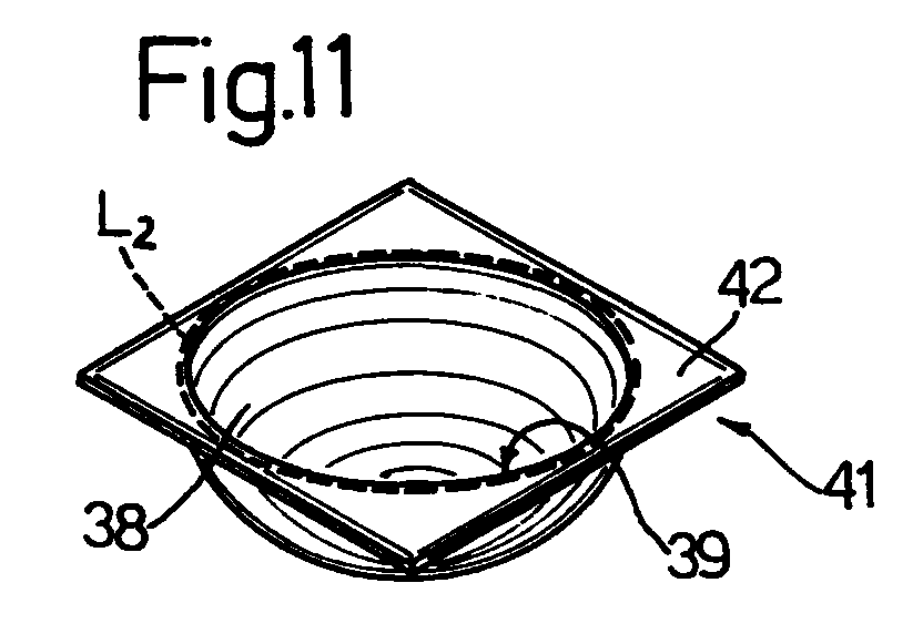
- Cutting unit 37 then makes a first cut of strip 31 along a cutting line L1 ( Figure 10), e.g. substantially crosswise to the traveling direction of strip 31, to form a body 41 ( Figure 11) comprising, in addition to hemispherical bowl 38, an outer flange 42 extending from an outer edge of hemispherical bowl 38.
- a known cutting unit (not shown) then makes a second cut along a closed cutting line L2 substantially coincident with an outer edge of hemispherical bowl 38, to form a first hemispherical hollow blank 43 ( Figure 12) and a second flat annular blank 44. Simultaneously with the second cut, a further two cuts are made in diametrically-opposed portions of bowl 38 - eventually defining portions 4 and 5 - to form slit 14 and tab 15.
- body 2 may be set to the closed position in which portions 4 and 5 overlap, and tab 15 positively engages slit 14.
- Tab 15 is released from slit 14, and hence package 1 opened, by rotating portions 4 and 5 further and in the same direction as before about axis 3, 47, and then releasing them to allow body 2 to return automatically to the open position.
- Blank 44 is deformed and possibly cut again to form a supporting element for body 2, or to form element 26.
- retaining device 13 comprises seat 15a and projection 16 ( Figure 3), a permanent deformation operation, conveniently a drawing operation, is substituted for said further cuts.
- Package 1a is formed in the same way as package 1, except for comprising the further step of removing both the end portions of body 2 close to the vertices to form the two openings 24 coaxial with axis 3, each of which is then closed by a respective cover element 25.
- package 1b differs from that of package 1 by comprising the further operation of folding a portion of blank 43, not affected by the cuts to form tab 15 and slit 14, towards a diametrically-opposed portion of blank 43 to form an outwardly-open hollow portion 48, on the edge of which one of said bends 46 is subsequently formed.
- Packages 1, 1a, 1b as described therefore comprise respective bodies 2, 23, 28, each formed from a flat blank of sheet material, and each having no cuts or preformed bend lines. Bodies 2 and 23 are even formed in one piece. Unlike known packages, packages 1, 1a, 1b therefore maintain not only their original configuration but also, and above all, their original appearance.
- Packages 1, 1a, 1b as described are therefore extremely easy to produce, can all be produced on commonly used tools, and are therefore extremely cheap to make, while at the same time maintaining a high standard of appearance.
- bodies 2, 23, 28 may differ from those described by way of example.
- the final shape in fact of bodies 2, 23, 28 is a direct result of the shape of hollow blank 43, which may differ in form and shape from those described, and, in particular, may comprise a number of different integral hollow bodies of revolution.
- the shape of blank 43 in fact obviously depends exclusively on the shape of punch 35 and cavity 34.
- Packages 1, 1a, 1b as described may obviously comprise retaining devices, for maintaining respective bodies 2, 23, 28 in the closed position, other than those described by way of example, and may also comprise gripping means, such as one or more rigid or flexible handles.
- Packages 1, 1a, 1b as described may obviously be used for applications other than that described by way of example.
- the packages may be used in combination with other, not necessarily similar, packages; for which purpose, each package may comprise connecting elements for connection to other packages and located, for example, close to the vertices of the respective body.
- each package 1, 1a, 1b may comprise at least one hanger element by which to hang the package to a respective supporting element.
- the hanger element may comprise a first elongated portion, e.g. a cord or chain, and a second fastening portion housed at least partly inside the respective body.
Landscapes
- Engineering & Computer Science (AREA)
- Mechanical Engineering (AREA)
- Ceramic Engineering (AREA)
- Auxiliary Devices For And Details Of Packaging Control (AREA)
- Making Paper Articles (AREA)
- Containers And Plastic Fillers For Packaging (AREA)
- Packages (AREA)
- Laminated Bodies (AREA)
- Containers Having Bodies Formed In One Piece (AREA)
- Blow-Moulding Or Thermoforming Of Plastics Or The Like (AREA)
Abstract

Description
Claims (19)
- A method of producing a package (1; 1a; 1b), particularly for packaging products, characterized by comprising the steps of feeding a sheet material (31) to a forming station; permanently deforming said sheet material (31) to form a hollow portion (38); cutting said sheet material (31) to form a hollow semifinished body (41; 43) having at least one inlet opening (39); forming on said hollow semifinished body (41; 43) two localized bends (46) on opposite sides of said opening (39) and aligned with each other along an axis (47); and permanently deforming said semifinished body (41; 43) by rotating two portions of the semifinished body (41; 43), located on opposite sides of said axis (47), about the axis (47) to form a body (2; 23; 28) in a stable, partly-open configuration.
- A method as claimed in Claim 1, characterized by comprising the further step of forming a retaining device (13) for maintaining said body (2; 23; 28) in an unstable configuration in which said opening (39) is at least partly closed.
- A method as claimed in Claim 1 or 2, characterized in that said cutting step comprises at least one cutting operation along a first cutting line (L2) substantially coincident with an edge defining said opening (39), so as to form a hollow body of revolution (43).
- A method as claimed in Claim 3, characterized in that said bends (46) are formed on said edge.
- A method as claimed in Claim 3 or 4, characterized in that said cutting operation comprises a second cutting operation to cut said sheet material (31) along a second cutting line (L1), at a distance from said first cutting line (L2), to form a blank (44) by which to define a supporting element for said body (2; 23; 28).
- A method as claimed in any one of the foregoing Claims, characterized in that said cutting operation comprises a third cutting operation to form at least one opening (24) through which, when formation is complete, said axis (47) extends.
- A method as claimed in any one of the foregoing Claims, characterized by comprising the further step of permanently deforming one portion (48) of said semifinished body (43), through which said axis (47) extends when formation is complete, towards an opposite portion of the semifinished body (43), through which said axis (47) also extends, so as to form on said body (2; 23; 28) an outwardly-open cavity having an inlet opening defined by a respective annular edge (29).
- A method as claimed in any one of the foregoing Claims from 2 to 7, when dependent on Claim 2, characterized in that the formation of said retaining device (13) comprises the steps of forming, on each said portion of said hollow semifinished body (43), a respective cut along a respective cutting line to form, on said body (2; 23; 28), at least a tab (15) and at least a seat (14) positively engageable by said tab (15).
- A method as claimed in any one of the foregoing Claims from 2 to 7, when dependent on Claim 2, characterized in that the formation of said retaining device (13) comprises the steps of deforming at least one portion of one of said portions to form a retaining seat (15a), and at least one portion of the other of said portions to form a projection (16) for positively engaging said retaining seat (15a).
- A method as claimed in any one of the foregoing Claims from 2 to 7, when dependent on Claim 2, characterized in that the formation of said retaining device (13) comprises the steps of fitting said body (2; 23; 28) with a retaining element (18) having portions (20) positively engaging each other in releasable manner.
- A method as claimed in any one of the foregoing Claims from 2 to 7, when dependent on Claim 2, characterized in that the formation of said retaining device (13) comprises the steps of forming an annular element (21), and fitting the annular element (21) on to the body (2; 23; 28) when the body (2; 23; 28) is in a condition close to said at least partly-closed configuration.
- A package, particularly for packaging products, characterized by comprising an elongated body (2; 23; 28) having an axis (3) and formed from a single piece of permanently deformable sheet material; the body (2; 23; 28) comprising two concave portions (4)(5) defining at least one inlet opening (12) and movable, with respect to each other and about said axis (3), between a parted position corresponding to a stable open configuration of the body (2; 23; 28), and a mating position corresponding to an unstable closed configuration of the body (2; 23; 28); releasable retaining means (13) being provided to maintain said body (2; 23; 28) in said unstable closed configuration.
- A package as claimed in Claim 12, characterized by also comprising at least a further inlet opening (24) through which said axis (3) extends.
- A package as claimed in Claim 13, characterized by comprising closing means (25) for closing said further opening (24); and connecting means (27) for connecting said closing means (25) to said body (2; 23; 28).
- A package as claimed in one of the foregoing Claims from 12 to 14, characterized in that said retaining means (13) comprise a first retaining element (15; 16) carried by one of said portions (4)(5); and a retaining seat (14; 15a) formed on the other of said portions (4) (5) and positively engaged in releasable manner by said retaining element (15; 16).
- A package as claimed in one of the foregoing Claims from 12 to 14, characterized in that said retaining means (13) comprise at least a curved blade element (18) fitted to said body (2; 23; 28); first and second connecting means (20) being provided to releasably connect opposite end portions of said curved blade element (18).
- A package as claimed in Claim 16, characterized in that said curved blade element (18) comprises at least an elastic intermediate portion (19), which, in use, provides for moving the body (2; 23; 28) into the stable open configuration.
- A package as claimed in any one of the foregoing Claims from 12 to 14, characterized in that said retaining means (13) comprise at least an annular element (21) fitted to the body (2; 23; 28).
- A package as claimed in any one of the foregoing Claims from 12 to 17, characterized in that said body (2; 23; 28) is made of thermoplastic material.
Applications Claiming Priority (2)
| Application Number | Priority Date | Filing Date | Title |
|---|---|---|---|
| IT97TO000238A IT1291939B1 (en) | 1997-03-21 | 1997-03-21 | METHOD FOR MAKING A WRAP, PARTICULARLY FOR THE PACKAGING OF PRODUCTS, AND THE ENVELOPE MADE WITH THIS METHOD. |
| ITTO970238 | 1997-03-21 |
Publications (3)
| Publication Number | Publication Date |
|---|---|
| EP0865902A2 true EP0865902A2 (en) | 1998-09-23 |
| EP0865902A3 EP0865902A3 (en) | 1999-06-30 |
| EP0865902B1 EP0865902B1 (en) | 2003-02-19 |
Family
ID=11415573
Family Applications (1)
| Application Number | Title | Priority Date | Filing Date |
|---|---|---|---|
| EP98105025A Expired - Lifetime EP0865902B1 (en) | 1997-03-21 | 1998-03-19 | Package and method of producing it |
Country Status (8)
| Country | Link |
|---|---|
| US (1) | US6027437A (en) |
| EP (1) | EP0865902B1 (en) |
| JP (1) | JPH10315314A (en) |
| AT (1) | ATE232792T1 (en) |
| DE (1) | DE69811415T2 (en) |
| ES (1) | ES2190553T3 (en) |
| IT (1) | IT1291939B1 (en) |
| PL (1) | PL192128B1 (en) |
Families Citing this family (4)
| Publication number | Priority date | Publication date | Assignee | Title |
|---|---|---|---|---|
| US7243809B2 (en) * | 2005-05-31 | 2007-07-17 | David Bezar | Gift wrapping package and method of use |
| US7243482B2 (en) * | 2005-05-31 | 2007-07-17 | David Bezar | Gift wrapping package and method of use |
| US20110204049A1 (en) * | 2005-07-22 | 2011-08-25 | Weder Donald E | Collapsible and/or erectable substantially egg-shaped container |
| US20070017915A1 (en) * | 2005-07-22 | 2007-01-25 | Weder Donald E | Collapsible and/or erectable substantially egg-shaped container |
Family Cites Families (3)
| Publication number | Priority date | Publication date | Assignee | Title |
|---|---|---|---|---|
| DE598113C (en) * | 1930-10-31 | 1934-06-07 | Wander Ag Dr A | Process for the packaging of easily deformable objects that can be changed by contact with the air |
| FR1582604A (en) * | 1968-08-09 | 1969-10-03 | ||
| CA2193386A1 (en) * | 1994-06-20 | 1995-12-28 | Robin P. Neary | Method for forming corrugated paper container and container made therefrom |
-
1997
- 1997-03-21 IT IT97TO000238A patent/IT1291939B1/en active IP Right Grant
-
1998
- 1998-03-18 US US09/040,855 patent/US6027437A/en not_active Expired - Fee Related
- 1998-03-19 AT AT98105025T patent/ATE232792T1/en not_active IP Right Cessation
- 1998-03-19 ES ES98105025T patent/ES2190553T3/en not_active Expired - Lifetime
- 1998-03-19 DE DE69811415T patent/DE69811415T2/en not_active Expired - Fee Related
- 1998-03-19 EP EP98105025A patent/EP0865902B1/en not_active Expired - Lifetime
- 1998-03-19 JP JP7058798A patent/JPH10315314A/en active Pending
- 1998-03-20 PL PL325456A patent/PL192128B1/en unknown
Also Published As
| Publication number | Publication date |
|---|---|
| ES2190553T3 (en) | 2003-08-01 |
| DE69811415D1 (en) | 2003-03-27 |
| DE69811415T2 (en) | 2004-01-15 |
| JPH10315314A (en) | 1998-12-02 |
| EP0865902B1 (en) | 2003-02-19 |
| PL325456A1 (en) | 1998-09-28 |
| EP0865902A3 (en) | 1999-06-30 |
| US6027437A (en) | 2000-02-22 |
| IT1291939B1 (en) | 1999-01-21 |
| ATE232792T1 (en) | 2003-03-15 |
| ITTO970238A1 (en) | 1998-09-21 |
| PL192128B1 (en) | 2006-09-29 |
Similar Documents
| Publication | Publication Date | Title |
|---|---|---|
| TWI608972B (en) | Systems and related methods for manufacturing ring pull ? ????????????????????????????? bottle crowns | |
| US20190337667A1 (en) | Composite Package, Package Laminate and Package Sleeve Blank for a Composite Package | |
| US20020189964A1 (en) | Product packaging having a non-thermoformed blister-like compartment and methods for making same | |
| EP3074316B1 (en) | Packaging and packaging blank | |
| EP2049326A2 (en) | Bottom finishing station components for a cup making machine | |
| HUP0001597A2 (en) | Method and device for wrapping a product in a sheet material wrapper and respective wrapped product | |
| USD999636S1 (en) | Packing container closure | |
| CH687976A5 (en) | Sheet material wrapping method | |
| CN105936379A (en) | Blister card with flange strap | |
| US6027437A (en) | Method of producing a package, particularly for packaging products, and package formed using such a method | |
| USD1046617S1 (en) | Packaging container blank | |
| CA2733439A1 (en) | Device apparatus and process for wrapping an item in a casing of sheet material | |
| JP4728578B2 (en) | Lid with sealing foil including holding means | |
| EP1365964A1 (en) | A foodstuffs container and the method for producing the container | |
| US20070221677A1 (en) | Container lid | |
| JP2016523778A (en) | Crown cap | |
| AU749776B2 (en) | Process for producing a metal can with an insert piece for packaging, for example, a foodstuff, and a can of this nature | |
| JP3107968U (en) | Punching mold for packaging containers | |
| US6471629B1 (en) | Tooling for forming packaging from unitary blanks | |
| EP4696473A1 (en) | Arrangement for cutting a web of packaging material into individual blanks | |
| EP1080870A3 (en) | Method for forming a hermetic flange seal in a blow-molded plastic container | |
| JP3055607U (en) | Paper container | |
| CN212288931U (en) | Crease structure for preventing box cover of packing box from tilting | |
| JP2004122410A (en) | Paper sheet molding | |
| GB2223485A (en) | Crown cap |
Legal Events
| Date | Code | Title | Description |
|---|---|---|---|
| PUAI | Public reference made under article 153(3) epc to a published international application that has entered the european phase |
Free format text: ORIGINAL CODE: 0009012 |
|
| AK | Designated contracting states |
Kind code of ref document: A2 Designated state(s): AT BE CH DE ES FR GB LI NL |
|
| AX | Request for extension of the european patent |
Free format text: AL;LT;LV;MK;RO;SI |
|
| PUAL | Search report despatched |
Free format text: ORIGINAL CODE: 0009013 |
|
| AK | Designated contracting states |
Kind code of ref document: A3 Designated state(s): AT BE CH DE DK ES FI FR GB GR IE IT LI LU MC NL PT SE |
|
| AX | Request for extension of the european patent |
Free format text: AL;LT;LV;MK;RO;SI |
|
| 17P | Request for examination filed |
Effective date: 19991124 |
|
| AKX | Designation fees paid |
Free format text: AT BE CH DE ES FR GB LI NL |
|
| 17Q | First examination report despatched |
Effective date: 20010125 |
|
| GRAG | Despatch of communication of intention to grant |
Free format text: ORIGINAL CODE: EPIDOS AGRA |
|
| GRAG | Despatch of communication of intention to grant |
Free format text: ORIGINAL CODE: EPIDOS AGRA |
|
| GRAH | Despatch of communication of intention to grant a patent |
Free format text: ORIGINAL CODE: EPIDOS IGRA |
|
| GRAH | Despatch of communication of intention to grant a patent |
Free format text: ORIGINAL CODE: EPIDOS IGRA |
|
| GRAA | (expected) grant |
Free format text: ORIGINAL CODE: 0009210 |
|
| AK | Designated contracting states |
Designated state(s): AT BE CH DE ES FR GB LI NL |
|
| REG | Reference to a national code |
Ref country code: GB Ref legal event code: FG4D |
|
| REG | Reference to a national code |
Ref country code: CH Ref legal event code: EP |
|
| REF | Corresponds to: |
Ref document number: 69811415 Country of ref document: DE Date of ref document: 20030327 Kind code of ref document: P |
|
| REG | Reference to a national code |
Ref country code: CH Ref legal event code: NV Representative=s name: NOVAGRAAF INTERNATIONAL SA |
|
| REG | Reference to a national code |
Ref country code: ES Ref legal event code: FG2A Ref document number: 2190553 Country of ref document: ES Kind code of ref document: T3 |
|
| ET | Fr: translation filed | ||
| PLBE | No opposition filed within time limit |
Free format text: ORIGINAL CODE: 0009261 |
|
| STAA | Information on the status of an ep patent application or granted ep patent |
Free format text: STATUS: NO OPPOSITION FILED WITHIN TIME LIMIT |
|
| 26N | No opposition filed |
Effective date: 20031120 |
|
| PGFP | Annual fee paid to national office [announced via postgrant information from national office to epo] |
Ref country code: FR Payment date: 20060313 Year of fee payment: 9 |
|
| PGFP | Annual fee paid to national office [announced via postgrant information from national office to epo] |
Ref country code: CH Payment date: 20060323 Year of fee payment: 9 |
|
| PGFP | Annual fee paid to national office [announced via postgrant information from national office to epo] |
Ref country code: AT Payment date: 20060324 Year of fee payment: 9 |
|
| PGFP | Annual fee paid to national office [announced via postgrant information from national office to epo] |
Ref country code: DE Payment date: 20060330 Year of fee payment: 9 |
|
| PGFP | Annual fee paid to national office [announced via postgrant information from national office to epo] |
Ref country code: NL Payment date: 20060331 Year of fee payment: 9 |
|
| PGFP | Annual fee paid to national office [announced via postgrant information from national office to epo] |
Ref country code: BE Payment date: 20060403 Year of fee payment: 9 |
|
| PGFP | Annual fee paid to national office [announced via postgrant information from national office to epo] |
Ref country code: ES Payment date: 20060417 Year of fee payment: 9 |
|
| REG | Reference to a national code |
Ref country code: CH Ref legal event code: PL |
|
| PG25 | Lapsed in a contracting state [announced via postgrant information from national office to epo] |
Ref country code: AT Free format text: LAPSE BECAUSE OF NON-PAYMENT OF DUE FEES Effective date: 20070319 |
|
| GBPC | Gb: european patent ceased through non-payment of renewal fee |
Effective date: 20070319 |
|
| NLV4 | Nl: lapsed or anulled due to non-payment of the annual fee |
Effective date: 20071001 |
|
| BERE | Be: lapsed |
Owner name: *PAROS S.R.L. Effective date: 20070331 |
|
| PG25 | Lapsed in a contracting state [announced via postgrant information from national office to epo] |
Ref country code: BE Free format text: LAPSE BECAUSE OF NON-PAYMENT OF DUE FEES Effective date: 20070331 |
|
| REG | Reference to a national code |
Ref country code: FR Ref legal event code: ST Effective date: 20071130 |
|
| PG25 | Lapsed in a contracting state [announced via postgrant information from national office to epo] |
Ref country code: NL Free format text: LAPSE BECAUSE OF NON-PAYMENT OF DUE FEES Effective date: 20071001 Ref country code: DE Free format text: LAPSE BECAUSE OF NON-PAYMENT OF DUE FEES Effective date: 20071002 |
|
| PG25 | Lapsed in a contracting state [announced via postgrant information from national office to epo] |
Ref country code: CH Free format text: LAPSE BECAUSE OF NON-PAYMENT OF DUE FEES Effective date: 20070331 Ref country code: LI Free format text: LAPSE BECAUSE OF NON-PAYMENT OF DUE FEES Effective date: 20070331 |
|
| PG25 | Lapsed in a contracting state [announced via postgrant information from national office to epo] |
Ref country code: GB Free format text: LAPSE BECAUSE OF NON-PAYMENT OF DUE FEES Effective date: 20070319 |
|
| REG | Reference to a national code |
Ref country code: ES Ref legal event code: FD2A Effective date: 20070320 |
|
| PG25 | Lapsed in a contracting state [announced via postgrant information from national office to epo] |
Ref country code: FR Free format text: LAPSE BECAUSE OF NON-PAYMENT OF DUE FEES Effective date: 20070402 Ref country code: ES Free format text: LAPSE BECAUSE OF NON-PAYMENT OF DUE FEES Effective date: 20070320 |
|
| PGFP | Annual fee paid to national office [announced via postgrant information from national office to epo] |
Ref country code: GB Payment date: 20060316 Year of fee payment: 9 |