EP0865945A1 - Luftverteilungsvorrichtung zur Heizung und/oder Klimatisierung eines Fahrzeuginnenraumes - Google Patents
Luftverteilungsvorrichtung zur Heizung und/oder Klimatisierung eines Fahrzeuginnenraumes Download PDFInfo
- Publication number
- EP0865945A1 EP0865945A1 EP98400607A EP98400607A EP0865945A1 EP 0865945 A1 EP0865945 A1 EP 0865945A1 EP 98400607 A EP98400607 A EP 98400607A EP 98400607 A EP98400607 A EP 98400607A EP 0865945 A1 EP0865945 A1 EP 0865945A1
- Authority
- EP
- European Patent Office
- Prior art keywords
- outlet
- flap
- ventilation
- air
- feet
- Prior art date
- Legal status (The legal status is an assumption and is not a legal conclusion. Google has not performed a legal analysis and makes no representation as to the accuracy of the status listed.)
- Granted
Links
Images

Classifications
-
- B—PERFORMING OPERATIONS; TRANSPORTING
- B60—VEHICLES IN GENERAL
- B60H—ARRANGEMENTS OF HEATING, COOLING, VENTILATING OR OTHER AIR-TREATING DEVICES SPECIALLY ADAPTED FOR PASSENGER OR GOODS SPACES OF VEHICLES
- B60H1/00—Heating, cooling or ventilating devices
- B60H1/00642—Control systems or circuits; Control members or indication devices for heating, cooling or ventilating devices
- B60H1/00664—Construction or arrangement of damper doors
- B60H1/00671—Damper doors moved by rotation; Grilles
-
- B—PERFORMING OPERATIONS; TRANSPORTING
- B60—VEHICLES IN GENERAL
- B60H—ARRANGEMENTS OF HEATING, COOLING, VENTILATING OR OTHER AIR-TREATING DEVICES SPECIALLY ADAPTED FOR PASSENGER OR GOODS SPACES OF VEHICLES
- B60H1/00—Heating, cooling or ventilating devices
- B60H1/00642—Control systems or circuits; Control members or indication devices for heating, cooling or ventilating devices
- B60H1/00664—Construction or arrangement of damper doors
- B60H2001/00721—Air deflecting or air directing means
Definitions
- the invention relates to an air distribution device for the heating and / or air conditioning of the passenger compartment of a vehicle.
- a device of the type comprising a distribution chamber of general shape cylindrical, with an air inlet and at least three air outlets located on the periphery of the distribution chamber, as well as a butterfly flap mounted to pivot around a axis inside the distribution chamber to control air distribution through the air outlets.
- the distribution chamber is connected to three air outlets, i.e. a defrost outlet specific to supply defrost / demister nozzles to the windscreen, a ventilation outlet suitable for supplying ventilation nozzles provided on the dashboard of the vehicle, and an outlet feet suitable for supplying nozzles directed towards the part lower part of the vehicle interior.
- This device has the particular disadvantage that the flap must rotate a large angular interval (close to 180 °) between its two extreme positions, which affects compactness of the device.
- this known device does not provide a precise adjustment of the distribution for certain positions of the shutter.
- the distribution chamber also constitutes a mixing chamber in which mix a cold air flow and a hot air flow, adjustable proportions, to provide temperature control air to distribute.
- the butterfly flap does not allow an intimate mixture of these two air flows, at least for certain positions of the shutter.
- the object of the invention is in particular to overcome the drawbacks cited above.
- the shutter is provided at least one arch-shaped part comprising a wall shutter defined by generators parallel to the axis pivoting of the shutter, said closure wall being connected to the flap by two spaced flanges, so that the sealing wall and the two flanges jointly delimit an air passage and that the sealing wall is clean to close, at least in part, one of the three air outlets when the shutter is in a defined position.
- the component of the invention constitutes what can be call a “mixed flap” including a combined butterfly flap to an arch, which can also be called “drum part”.
- This arch-shaped part allows you to close more or less one of the three air outlets, while the butterfly flap adjusts the distribution between the other two air outlets, allowing precise adjustment of the distribution.
- the flap of the device of the invention makes it possible to distribute the distribution between three air outlets, and this with a deflection angle generally close to 90 °, this which allows to limit the size.
- the air passage defined by the shaped part arch contributes to a better mixture of cold air flow and the hot air flow, when the distribution chamber constitutes a mixing chamber.
- the end wall is a partially cylindrical wall circular centered on the pivot axis of the flap. This cylindrical wall advantageously extends over an interval angular less than 45 °.
- the flanges of the arch-shaped part attach perpendicularly at the shutter.
- these flanges are attached to the two wings that includes the shutter.
- the invention provides that the flap is fitted with a peripheral seal.
- the three air outlets include a defrost outlet, a ventilation outlet and a feet outlet.
- the sealing wall of the shaped part arch is advantageously suitable for closing the foot outlet in said defined position of the flap.
- This defined position preferably corresponds to a ventilation position in which the defrost outlet is closed by a first wing of the flap and the ventilation outlet is opened by a second wing of the flap, the outlet ventilation being supplied by an air flow passing through the passage delimited by the arch-shaped part.
- this defined position, or ventilation position constitutes a first extreme position of the flap.
- the component is likely to take a second extreme position in which the first wing of the shutter opens the defrost outlet, while the second wing of the shutter closes the ventilation outlet and the feet outlet, which are adjacent.
- the second wing of the flap has a cylindrical wall section at its end circular, centered on the axis of rotation of the shutter and extending on the side opposite the arch-shaped part, said wall section being able to cooperate, in a position intermediate of the flap, with an internal wall of the housing which extends between the ventilation outlet and the feet outlet.
- This section of circular cylindrical wall which forms bearing cylindrical, mainly to prevent passage air to the ventilation outlet when the flap passes from one feet position to a defrost-feet position.
- the circular cylindrical wall section is suitable for engaging, in the ventilation position, in a groove-shaped housing, formed in a wall of the housing which defines the ventilation outlet. This avoids a air passage to the defrost outlet.
- the shutter has advantageously an angular movement, between the first and the second extreme position, which is about a quarter of turn.
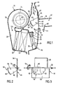
- the device shown in Figure 1 comprises a housing 10 housing an air blower 12 provided with a turbine 14 suitable for be rotated about an axis 16 by a motor electric (not shown).
- the turbine 14 is housed in a case 18 in the form of a scroll with a tangential outlet 20.
- the turbine 14 is suitable for being supplied axially by an air flow taken from outside and / or inside of the passenger compartment of the vehicle to produce a forced air flow (arrow F1) which leaves the casing 18 in the form of a volute by exit 20.
- the air flow F1 then successively passes through a filter 22, an evaporator 24 connected to an air conditioning circuit conventional, and a heating radiator 26.
- the radiator 26 is capable of being traversed by a heat transfer fluid which is usually the engine coolant the vehicle.
- This fluid enters the radiator 26 through a tube 28 controlled by an adjustable valve 30 and leaves the radiator 26 by an outlet pipe 32. It is thus possible produce, at the outlet of the heating radiator 26, a flow of air F2 at adjustable temperature.
- This air flow opens into a distribution chamber 34 of generally cylindrical shape, at least partly circular, delimited by a wall cylindrical 36 whose generators are parallel and equal distance from an X-X axis.
- the distribution chamber 34 is provided with an air inlet 38 (which is connected to the output of the heating radiator 26) and which supplies the chamber 34 with the air flow F2 at adjustable temperature.
- the distribution chamber 34 is in additionally provided with three air outlets located at its periphery, namely a defrost outlet 40, a ventilation outlet 42 and a 44 feet outlet.
- the defrost outlet 40 feeds an air outlet nozzle 46 which is formed directly with the housing 10. This nozzle 46 is suitable for defrosting / demisting the windshield vehicle.
- the output 42 feeds at least one ventilation nozzle (not shown) located on the dashboard of the vehicle.
- the output feet 44 feeds at least one nozzle (not shown) located in the lower part of the passenger compartment for send treated air to the area of the occupants' feet of the motor vehicle.
- a flap 46 of special structure which is pivotally mounted around the X-X axis.
- This component is a butterfly type component comprising a first wing 48 and a second wing 50 ( Figures 1 to 3) generally rectangular, located in the same plane, on either side of a shaft 52 extending in the direction of the X-X axis.
- a radial lever 54 ( Figures 2 and 3) which can be actuated by a connecting rod (not shown) connected to a control panel housed in the vehicle dashboard.
- the first wing 48 is suitable for controlling the defrost outlet 40, while the second wing 50 is specific to check the ventilation outlet 42 and the feet outlet 44.
- the wings 48 and 50 are provided, at their periphery, with a seal seal 56 which is overmolded ( Figure 2).
- the flap 46 is provided with an arch-shaped portion 58, which we can also call "drum part".
- This part 58 comprises a closure wall 60 (figures 1 to 3) defined by generatrices parallel to the axis of X-X pivoting of the shutter.
- This wall is a cylindrical wall partially circular centered on the pivot axis X-X and extending over an angular interval close to 45 ° (figure 2).
- the closure wall 60 is connected to the wings 48 and 50 of the flap 46 by two flanges 62 which are parallel between them and are attached perpendicularly to the wings 48 and 50.
- the arch-shaped part 58 thus delimits a passage interior 64 ( Figure 2) which channels the air flow F2.
- the main function of the closure wall 60 is to close, at least in part, the outlet feet 44 when the flap 46 is in a predefined position (FIG. 7), that is to say when this flap is in a position extreme, or at least in the vicinity of this position extreme.
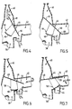
- the flap 46 can take a first extreme position, called “defrost position”, as shown in Figure 1, and a second extreme position, called “ventilation position”, as shown in Figure 7, passing through positions intermediates, as shown in Figures 4, 5 and 6.
- the flap In the intermediate position, called “defrost-feet position" in Figure 4, the flap has pivoted slightly by relative to the previous position (in the example in the sense anti-clockwise). Wing 48 partially opens the air outlet 40, while wing 50 partially opens the outlet feet 44. On the other hand, the ventilation outlet 42 is practically closed. Thus, the air flow F2 is divided into a flow F3 crossing the ventilation outlet 40 and a flow F4 crossing the feet outlet 44.
- the flap 46 has again pivoted relative to the previous position (always in the direction anti-clockwise).
- the wing 48 closes the outlet defrost 40
- wing 50 closes the ventilation outlet 42.
- the end of the wing 50 cooperates with sealing with a re-entrant edge 68 formed by the housing between the air outlets 42 and 44. Only a flow F4 crosses the outlet feet 44.
- the flap In the position of FIG. 6, the flap has again pivoted by relative to the previous position (always counterclockwise). In this position, the flap wing 48 ensures always closing the ventilation outlet 40, the end of the wing 48 coming to cooperate in sealing with the wall 36 of the distribution chamber 34. In this same position, the wing 50 opens the ventilation outlet 42 and the feet outlet 44, which are supplied with air as shown respectively by arrows F5 and F4.
- the wing 50 In the position of figure 7, which corresponds to another extreme position of the flap, the wing 50 is in abutment against a wall 70 of the housing which is substantially perpendicular to the wall 66. In this position, the wing 48 of the flap ensures always closing the defrost outlet 40, while the wing 50 ensures the opening of the ventilation outlet 42. By against, the closing wall 60 of the shaped portion 58 arch ensures the closure of the outlet feet 44.
- the air flow F2 feeds only the ventilation outlet 42, as shown by arrow F5.
- the air flow passes through the passage 64 of part 58 in the shape of an arch.
- closure wall 60 allows close more or less the 44 feet outlet and provide thus a multiplicity of intermediate positions between those of Figures 6 and 7 to provide precise adjustment of the air distribution between the ventilation outlet 42 and the output feet 44, which would not allow a butterfly flap classic.
- the second wing 50 of the flap 46 is provided, at its end, with a section of circular cylindrical wall 72 centered on the axis of X-X rotation of the flap and extending from the side opposite the part 58 in the shape of an arch.
- the flap 46 can occupy the five positions shown on Figure 8: defrost (1), defrost-feet (2), feet (3), foot ventilation (4) and ventilation (5).
- the ventilation position is shown in solid lines and the others in broken lines.
- the wall section 72 is intended to engage in a housing 74 formed in the wall 70 of the housing, which delimits the ventilation outlet 42 (FIG. 8).
- this accommodation 74 is produced in the form of a groove which is intended to accommodate the wall section 72 when the flap 46 is in the ventilation position.
- the air flow F2 feeds only the ventilation outlet 42, as shown by the arrow F5. Since the raised edge 72 is received in the housing 74, this prevents any passage of air towards the outlet defrost 40.
- the wing 48 of the flap 46 bears against a stop 76 (FIG. 8) formed in a wall delimiting the defrost outlet 40, which also helps to prevent the passage of an air flow to the defrost outlet 40.
- the wall section 72 cooperates with an interior wall 80 of the housing ( Figure 9) which extends between the ventilation outlet 42 and the outlet feet 44 and which has a cylindrical shape circular centered on axis XX.
- the wall section 72 is flush with the wall 80 in providing a seal, preventing any passage of air towards the ventilation outlet 42. If the wall section 72 was not not present, air leakage could occur through ventilation outlet in certain intermediate positions of the shutter for which air is not desired passes to the ventilation outlet.
- the distribution chamber 34 could, as a variant, constitute a mixing chamber fed by an air flow cold and a flow of hot air.
- the arch-shaped part, or drum part provides a better mixture of cold air / hot air and therefore reduce the temperature differences between the air outlets provided respectively in the upper part and in lower part of the case.
- the invention is not limited to a butterfly flap comprising a single arch-shaped part.
Landscapes
- Physics & Mathematics (AREA)
- Thermal Sciences (AREA)
- Engineering & Computer Science (AREA)
- Mechanical Engineering (AREA)
- Air-Conditioning For Vehicles (AREA)
Applications Claiming Priority (2)
| Application Number | Priority Date | Filing Date | Title |
|---|---|---|---|
| FR9703273 | 1997-03-18 | ||
| FR9703273A FR2761012B1 (fr) | 1997-03-18 | 1997-03-18 | Dispositif de distribution d'air pour le chauffage et/ou la climatisation de l'habitacle d'un vehicule |
Publications (2)
| Publication Number | Publication Date |
|---|---|
| EP0865945A1 true EP0865945A1 (de) | 1998-09-23 |
| EP0865945B1 EP0865945B1 (de) | 2002-08-21 |
Family
ID=9504910
Family Applications (1)
| Application Number | Title | Priority Date | Filing Date |
|---|---|---|---|
| EP19980400607 Expired - Lifetime EP0865945B1 (de) | 1997-03-18 | 1998-03-16 | Luftverteilungsvorrichtung zur Heizung und/oder Klimatisierung eines Fahrzeuginnenraumes |
Country Status (4)
| Country | Link |
|---|---|
| EP (1) | EP0865945B1 (de) |
| BR (1) | BR9800918A (de) |
| DE (1) | DE69807275T2 (de) |
| FR (1) | FR2761012B1 (de) |
Cited By (12)
| Publication number | Priority date | Publication date | Assignee | Title |
|---|---|---|---|---|
| FR2789017A1 (fr) * | 1999-01-29 | 2000-08-04 | Valeo Climatisation | Dispositif de distribution d'un air d'aeration dans l'habitacle d'un vehicule automobile |
| DE10052135A1 (de) * | 2000-10-20 | 2002-05-02 | Valeo Klimasysteme Gmbh | Luftführungsgehäuse |
| EP1306240A2 (de) | 2001-10-24 | 2003-05-02 | Behr GmbH & Co. | Luftstromsteuereinrichtung |
| FR2833530A1 (fr) * | 2001-12-18 | 2003-06-20 | Valeo Climatisation | Appareil de chauffage et/ou de climatisation a organe de mixage et de repartition d'air pour habitacle de vehicule automobile |
| CN100431864C (zh) * | 2004-04-15 | 2008-11-12 | 瓦莱奥空调系统有限公司 | 用于汽车通风系统的导气系统 |
| EP2407324A1 (de) * | 2010-07-16 | 2012-01-18 | Behr France Rouffach SAS | Luftregulierungselement für eine Heizungs- und Belüftungsvorrichtung für ein Kraftfahrzeug sowie Heizungs- und Belüftungsvorrichtung für einen Fahrgastraum eines Kraftfahrzeuges |
| EP2679417A1 (de) * | 2012-06-25 | 2014-01-01 | Valeo Autoklimatizace k.s. | Fahrzeugheizungs-, Belüftungs und/oder Konditionierungseinheit |
| US20150217629A1 (en) * | 2014-02-04 | 2015-08-06 | Calsonic Kansel Corporation | Vehicle air conditioner |
| EP2918431A1 (de) * | 2011-12-23 | 2015-09-16 | Valeo Systemes Thermiques | Gehäuse für eine Einheit zum Heizen, Lüften und/oder Klimatisieren, und Klappe für ein solches Gehäuse |
| US20180141407A1 (en) * | 2016-11-23 | 2018-05-24 | Hyundai Motor Company | Air Conditioning Apparatus for Vehicle |
| US10106188B2 (en) | 2016-10-21 | 2018-10-23 | Hyundai Motor Company | Steering wheel cooling system |
| CN117845579A (zh) * | 2023-12-29 | 2024-04-09 | 珠海格力电器股份有限公司 | 风道系统、双筒衣物处理设备及烘干方法 |
Families Citing this family (3)
| Publication number | Priority date | Publication date | Assignee | Title |
|---|---|---|---|---|
| FR2821588B1 (fr) * | 2001-03-02 | 2003-09-05 | Valeo Climatisation | Ensemble de chauffage et/ou de climatisation equipe de volets mobiles pour habitacle de vehicule automobile et vehicule ainsi equipe |
| DE102011080214A1 (de) * | 2011-08-01 | 2013-02-07 | Behr Gmbh & Co. Kg | Heiz- oder Klimaanlage, insbesondere für ein Kraftfahrzeug |
| DE102014105115B8 (de) | 2014-04-10 | 2025-04-30 | Hanon Systems | Luftleiteinrichtung einer Klimatisierungsvorrichtung eines Kraftfahrzeugs |
Citations (5)
| Publication number | Priority date | Publication date | Assignee | Title |
|---|---|---|---|---|
| GB2077417A (en) | 1980-02-27 | 1981-12-16 | Saab Scania Ab | Arrangement for distributing ventilation air in vehicles |
| US4947735A (en) * | 1988-05-27 | 1990-08-14 | Valeo | Distribution box for a heating and/or air conditioning apparatus, especially for an automotive vehicle |
| EP0423778A2 (de) * | 1989-10-20 | 1991-04-24 | BORLETTI CLIMATIZZAZIONE S.r.l. | Luftverteiler für Klimaanlage von Kraftfahrzeugen |
| DE4305253A1 (de) * | 1993-02-20 | 1994-08-25 | Opel Adam Ag | Heiz- und Belüftungseinrichtung |
| FR2728515A1 (fr) * | 1994-12-22 | 1996-06-28 | Valeo Thermique Habitacle | Dispositif de distribution d'air dans l'habitacle d'un vehicule |
-
1997
- 1997-03-18 FR FR9703273A patent/FR2761012B1/fr not_active Expired - Fee Related
-
1998
- 1998-03-16 DE DE1998607275 patent/DE69807275T2/de not_active Expired - Fee Related
- 1998-03-16 EP EP19980400607 patent/EP0865945B1/de not_active Expired - Lifetime
- 1998-03-17 BR BR9800918A patent/BR9800918A/pt not_active IP Right Cessation
Patent Citations (5)
| Publication number | Priority date | Publication date | Assignee | Title |
|---|---|---|---|---|
| GB2077417A (en) | 1980-02-27 | 1981-12-16 | Saab Scania Ab | Arrangement for distributing ventilation air in vehicles |
| US4947735A (en) * | 1988-05-27 | 1990-08-14 | Valeo | Distribution box for a heating and/or air conditioning apparatus, especially for an automotive vehicle |
| EP0423778A2 (de) * | 1989-10-20 | 1991-04-24 | BORLETTI CLIMATIZZAZIONE S.r.l. | Luftverteiler für Klimaanlage von Kraftfahrzeugen |
| DE4305253A1 (de) * | 1993-02-20 | 1994-08-25 | Opel Adam Ag | Heiz- und Belüftungseinrichtung |
| FR2728515A1 (fr) * | 1994-12-22 | 1996-06-28 | Valeo Thermique Habitacle | Dispositif de distribution d'air dans l'habitacle d'un vehicule |
Cited By (16)
| Publication number | Priority date | Publication date | Assignee | Title |
|---|---|---|---|---|
| US6296563B1 (en) | 1998-01-29 | 2001-10-02 | Valeo Climatisation | Device for the distribution of ventilation air in the passenger compartment of a motor vehicle |
| FR2789017A1 (fr) * | 1999-01-29 | 2000-08-04 | Valeo Climatisation | Dispositif de distribution d'un air d'aeration dans l'habitacle d'un vehicule automobile |
| DE10052135A1 (de) * | 2000-10-20 | 2002-05-02 | Valeo Klimasysteme Gmbh | Luftführungsgehäuse |
| EP1306240A2 (de) | 2001-10-24 | 2003-05-02 | Behr GmbH & Co. | Luftstromsteuereinrichtung |
| DE10152597A1 (de) * | 2001-10-24 | 2003-05-08 | Behr Gmbh & Co | Luftstromsteuereinrichtung |
| FR2833530A1 (fr) * | 2001-12-18 | 2003-06-20 | Valeo Climatisation | Appareil de chauffage et/ou de climatisation a organe de mixage et de repartition d'air pour habitacle de vehicule automobile |
| CN100431864C (zh) * | 2004-04-15 | 2008-11-12 | 瓦莱奥空调系统有限公司 | 用于汽车通风系统的导气系统 |
| US7462099B2 (en) * | 2004-04-15 | 2008-12-09 | Valeo Klimasysteme Gmbh | Air-guiding system for a ventilation system of a vehicle |
| EP2407324A1 (de) * | 2010-07-16 | 2012-01-18 | Behr France Rouffach SAS | Luftregulierungselement für eine Heizungs- und Belüftungsvorrichtung für ein Kraftfahrzeug sowie Heizungs- und Belüftungsvorrichtung für einen Fahrgastraum eines Kraftfahrzeuges |
| EP2918431A1 (de) * | 2011-12-23 | 2015-09-16 | Valeo Systemes Thermiques | Gehäuse für eine Einheit zum Heizen, Lüften und/oder Klimatisieren, und Klappe für ein solches Gehäuse |
| EP2679417A1 (de) * | 2012-06-25 | 2014-01-01 | Valeo Autoklimatizace k.s. | Fahrzeugheizungs-, Belüftungs und/oder Konditionierungseinheit |
| US20150217629A1 (en) * | 2014-02-04 | 2015-08-06 | Calsonic Kansel Corporation | Vehicle air conditioner |
| US10106188B2 (en) | 2016-10-21 | 2018-10-23 | Hyundai Motor Company | Steering wheel cooling system |
| US20180141407A1 (en) * | 2016-11-23 | 2018-05-24 | Hyundai Motor Company | Air Conditioning Apparatus for Vehicle |
| US10864797B2 (en) * | 2016-11-23 | 2020-12-15 | Hyundai Motor Company | Air conditioning apparatus for vehicle |
| CN117845579A (zh) * | 2023-12-29 | 2024-04-09 | 珠海格力电器股份有限公司 | 风道系统、双筒衣物处理设备及烘干方法 |
Also Published As
| Publication number | Publication date |
|---|---|
| DE69807275D1 (de) | 2002-09-26 |
| BR9800918A (pt) | 1999-09-14 |
| FR2761012A1 (fr) | 1998-09-25 |
| DE69807275T2 (de) | 2003-04-17 |
| FR2761012B1 (fr) | 1999-05-28 |
| EP0865945B1 (de) | 2002-08-21 |
Similar Documents
| Publication | Publication Date | Title |
|---|---|---|
| EP1013491B1 (de) | Fahrzeugklimaanlage mit verbesserter Luftmischung | |
| EP0865945B1 (de) | Luftverteilungsvorrichtung zur Heizung und/oder Klimatisierung eines Fahrzeuginnenraumes | |
| EP0266230B1 (de) | Mischklappe für Fahrzeugklimaanlagen und ähnliche Anwendungen | |
| FR2726229A1 (fr) | Dispositif de chauffage et/ou d'aeration pour l'habitacle d'un vehicule automobile | |
| EP0812714B1 (de) | Vorrichtung für die Heizung und/oder Lüftung eines Fahrzeuginnenraumes | |
| FR2720693A1 (fr) | Dispositif de chauffage et/ou d'aération de l'habitacle d'un véhicule. | |
| EP0656272B1 (de) | Verteilungsvorrichtung für eine Fahrzeugklimaanlage | |
| FR2788019A1 (fr) | Dispositif de distribution d'air pour le chauffage et/ou la climatisation d'un vehicule automobile | |
| FR2777225A1 (fr) | Installation de chauffage ou de climatisation pour vehicules comportant un echangeur de chaleur dans un conduit d'air et au moins une chambre de melange d'air | |
| WO2020174146A1 (fr) | Installation de chauffage et/ou ventilation et/ou climatisation comportant un volet de mixage avec déflecteur | |
| FR2777512A1 (fr) | Boitier d'admission d'air pour une installation de chauffage et/ou climatisation de vehicule automobile | |
| FR2766760A1 (fr) | Dispositif de distribution d'air pour le chauffage et/ou la climatisation de l'habitacle d'un vehicule | |
| FR2746714A1 (fr) | Dispositif de chauffage et/ou climatisation de l'habitacle d'un vehicule automobile | |
| FR2710878A1 (fr) | Dispositif du chauffage et de ventilation de l'habitacle d'un véhicule automobile. | |
| FR2761011A1 (fr) | Dispositif de chauffage-ventilation et/ou climatisation d'un vehicule, comprenant une commande par volet | |
| EP0749857B1 (de) | Vorrichtung zur Heizung, Lüftung eines Fahrzeuginnenraumes | |
| WO1999055545A1 (fr) | Dispositif de chauffage et/ou climatisation de l'habitacle d'un vehicule, avec mixage d'air ameliore | |
| FR2728515A1 (fr) | Dispositif de distribution d'air dans l'habitacle d'un vehicule | |
| FR2786134A1 (fr) | Dispositif de chauffage-ventilation de l'habitacle d'un vehicule | |
| FR2679621A1 (fr) | Dispositif de commande de volets, notamment de volets d'un appareil de chauffage ventilation et/ou de climatisation. | |
| FR2798322A1 (fr) | Dispositif de chauffage et/ou climatisation de vehicule automobile a distribution amelioree | |
| EP4457113A1 (de) | Schiebeklappe einer heiz-, lüftungs- und/oder klimaanlage für einen innenraum eines fahrzeugs | |
| FR2797810A1 (fr) | Calibrage des sections d'entree d'air dans une installation de climatisation de vehicule | |
| FR2836541A1 (fr) | Aerateur a volet, notamment pour habitacle de vehicule automobile | |
| EP1366935A1 (de) | Vorrichtung zur Erzeugung einer temperaturgeregelten Luftströmung und Gerät mit einer solchen Vorrichtung |
Legal Events
| Date | Code | Title | Description |
|---|---|---|---|
| PUAI | Public reference made under article 153(3) epc to a published international application that has entered the european phase |
Free format text: ORIGINAL CODE: 0009012 |
|
| AK | Designated contracting states |
Kind code of ref document: A1 Designated state(s): DE FR |
|
| AX | Request for extension of the european patent |
Free format text: AL;LT;LV;MK;RO;SI |
|
| 17P | Request for examination filed |
Effective date: 19990216 |
|
| AKX | Designation fees paid |
Free format text: DE FR |
|
| RBV | Designated contracting states (corrected) |
Designated state(s): DE FR |
|
| 17Q | First examination report despatched |
Effective date: 20000314 |
|
| GRAG | Despatch of communication of intention to grant |
Free format text: ORIGINAL CODE: EPIDOS AGRA |
|
| GRAG | Despatch of communication of intention to grant |
Free format text: ORIGINAL CODE: EPIDOS AGRA |
|
| GRAH | Despatch of communication of intention to grant a patent |
Free format text: ORIGINAL CODE: EPIDOS IGRA |
|
| GRAH | Despatch of communication of intention to grant a patent |
Free format text: ORIGINAL CODE: EPIDOS IGRA |
|
| GRAA | (expected) grant |
Free format text: ORIGINAL CODE: 0009210 |
|
| AK | Designated contracting states |
Kind code of ref document: B1 Designated state(s): DE FR |
|
| REF | Corresponds to: |
Ref document number: 69807275 Country of ref document: DE Date of ref document: 20020926 |
|
| PGFP | Annual fee paid to national office [announced via postgrant information from national office to epo] |
Ref country code: DE Payment date: 20030312 Year of fee payment: 6 |
|
| PGFP | Annual fee paid to national office [announced via postgrant information from national office to epo] |
Ref country code: FR Payment date: 20030328 Year of fee payment: 6 |
|
| PLBE | No opposition filed within time limit |
Free format text: ORIGINAL CODE: 0009261 |
|
| STAA | Information on the status of an ep patent application or granted ep patent |
Free format text: STATUS: NO OPPOSITION FILED WITHIN TIME LIMIT |
|
| 26N | No opposition filed |
Effective date: 20030522 |
|
| PG25 | Lapsed in a contracting state [announced via postgrant information from national office to epo] |
Ref country code: DE Free format text: LAPSE BECAUSE OF NON-PAYMENT OF DUE FEES Effective date: 20041001 |
|
| PG25 | Lapsed in a contracting state [announced via postgrant information from national office to epo] |
Ref country code: FR Free format text: LAPSE BECAUSE OF NON-PAYMENT OF DUE FEES Effective date: 20041130 |
|
| REG | Reference to a national code |
Ref country code: FR Ref legal event code: ST |