EP0865946A2 - Diffuseur d'air - Google Patents
Diffuseur d'air Download PDFInfo
- Publication number
- EP0865946A2 EP0865946A2 EP98103007A EP98103007A EP0865946A2 EP 0865946 A2 EP0865946 A2 EP 0865946A2 EP 98103007 A EP98103007 A EP 98103007A EP 98103007 A EP98103007 A EP 98103007A EP 0865946 A2 EP0865946 A2 EP 0865946A2
- Authority
- EP
- European Patent Office
- Prior art keywords
- bearing
- air vent
- joint part
- ventilation duct
- bearings
- Prior art date
- Legal status (The legal status is an assumption and is not a legal conclusion. Google has not performed a legal analysis and makes no representation as to the accuracy of the status listed.)
- Withdrawn
Links
Images

Classifications
-
- F—MECHANICAL ENGINEERING; LIGHTING; HEATING; WEAPONS; BLASTING
- F24—HEATING; RANGES; VENTILATING
- F24F—AIR-CONDITIONING; AIR-HUMIDIFICATION; VENTILATION; USE OF AIR CURRENTS FOR SCREENING
- F24F13/00—Details common to, or for air-conditioning, air-humidification, ventilation or use of air currents for screening
- F24F13/02—Ducting arrangements
- F24F13/06—Outlets for directing or distributing air into rooms or spaces, e.g. ceiling air diffuser
- F24F13/065—Outlets for directing or distributing air into rooms or spaces, e.g. ceiling air diffuser formed as cylindrical or spherical bodies which are rotatable
-
- B—PERFORMING OPERATIONS; TRANSPORTING
- B60—VEHICLES IN GENERAL
- B60H—ARRANGEMENTS OF HEATING, COOLING, VENTILATING OR OTHER AIR-TREATING DEVICES SPECIALLY ADAPTED FOR PASSENGER OR GOODS SPACES OF VEHICLES
- B60H1/00—Heating, cooling or ventilating devices
- B60H1/34—Nozzles; Air-diffusers
- B60H1/3414—Nozzles; Air-diffusers with means for adjusting the air stream direction
- B60H1/3435—Nozzles; Air-diffusers with means for adjusting the air stream direction using only a pivoting frame
-
- B—PERFORMING OPERATIONS; TRANSPORTING
- B64—AIRCRAFT; AVIATION; COSMONAUTICS
- B64D—EQUIPMENT FOR FITTING IN OR TO AIRCRAFT; FLIGHT SUITS; PARACHUTES; ARRANGEMENT OR MOUNTING OF POWER PLANTS OR PROPULSION TRANSMISSIONS IN AIRCRAFT
- B64D13/00—Arrangements or adaptations of air-treatment apparatus for aircraft crew or passengers, or freight space
- B64D2013/003—Cabin ventilation nozzles
Definitions
- the invention relates to an air vent with an End of a ventilation duct horizontally and vertically swivel-mounted cover with air outlets.
- Such air vents are used today, for example Motor vehicles for supplying fresh air into the interior used and are known from practice.
- the Aperture of the air vents is used to set one intended flow direction into the interior of Hand adjustable to a desired position.
- the aperture is hemispherical and is laterally by the Enclosed at the end of the ventilation duct.
- the air outlets are made of one-piece lamellas limited.
- the air vent is made of special few, inexpensive to manufacture and assemble Components.
- the end of the ventilation duct is in usually made up of two bowl - shaped parts Assembly of the air vent can be screwed together.
- the individual components of the air vent are in usually made of plastic by injection molding. As a result, the air vent has a particularly low level Weight and is inexpensive to manufacture.
- a disadvantage of the known air vents is that they have components that are difficult to manufacture by injection molding.
- the two are in manufacturing bowl-shaped parts of the ventilation duct a high precision required so the bezel is not in some positions stuck and in other positions by itself adjusted.
- the invention is based on the problem of an air vent of the type mentioned at the outset in such a way that he has particularly few components and a jamming of Aperture in different positions is avoided.
- the cover is like a universal joint attached to the ventilation duct.
- the invention Air vents are easy to spray and thus inexpensive bearings for the Bearing axles. Because the bearings are particularly small have tolerances or unevenness of the bearings did not cause the aperture to jam in individual Positions.
- the diaphragm can be hemispherical, for example or be cylindrical.
- the invention In the simplest case, air vents exist only three easy to assemble components.
- the installation of the air vent is according to one other advantageous development of the invention particularly easy when the bearings of the bearing axles in Bearing cups have pivotable trunnions and if the bearing shells encompass the trunnions by approximately 270 °. This allows the individual components of the Simply plug the air vent together.
- the aperture is strong air flow or vibrations of the motor vehicle remains in its set position.
- the provided manually in the known air vents can be adjusted according to a another advantageous development of the invention avoid if the ventilation duct, the joint part and the Cover biased against each other in the area of their bearings are. This can be done, for example, by pretensioning the bearing shells against the bearing journal or through axial bracing on the bearings can be achieved. With this design, the intended frictional force in the manufacture of the individual components of the air vent intended. A manual setting is therefore not necessary anymore.
- the ventilation duct seal with the cover with a sleeve could be the ventilation duct seal with the cover with a sleeve.
- the cuff is complex to assemble and can be according to another advantageous development avoid the invention when the bezel the hinge part and overlaps the end of the ventilation duct.
- the joint part in the center of the Aperture can be arranged.
- the aperture has the invention particularly small dimensions, if the ventilation duct the joint part and the joint part the Cover overlaps.
- the joint part seals the Cover against the ventilation duct. This will make the Air flow led through the joint part.
- the installation of the air vent is according to one advantageous development of the invention particularly easy if the aperture two protrudes radially outwards Bearing journal and the joint part bearing shells for the Bearing journal of the panel. This will make the The panel is pushed into the joint part during assembly and guided by the joint part. Since you do this Bearing shell and the bearing journal can be seen from the outside, can be easily checked whether the bearing pins in the Snap the bearing shells into place. Furthermore, the aperture is through the outwardly protruding bearing journals as injection molding particularly simple component.
- Air vent helps when the joint part radially protruding bearing journals and the ventilation duct Bores for the pivot pin of the joint part having.
- a risk of injury to the trunnion can be according to another advantageous development of the invention simply by avoiding that the trunnion is on have a bulge at their protruding end.
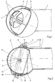
- Figure 1 shows an air vent according to the invention with a ventilation duct 1 and a panel 2.
- the panel 2 has a plurality of air outlets 3 and leaves about a horizontal bearing axis 4 and a vertical one Swivel bearing axis 5.
- FIG 2 is a longitudinal section through the air vent can be seen from Figure 1 that between the aperture 2 and the ventilation duct 1 a hinge part 6 is arranged is.
- the hinge part 6 is by means of two opposite one another Bearings 7, 8 around the vertical bearing axis 5 pivoted.
- the aperture 2 is by means of two compared to the bearings 7, 8 of the joint part 6 in the Ventilation duct 1 of bearings 9 rotated by 90 ° held pivotable.
- the hinge part 6 has two radially outward bearing journals 10, 11 in bearing shells 12, 13 of the ventilation duct 1 intervene.
- For the storage of the panel 2 has the joint part 6 bearing shells 14, in the radial engage outwardly protruding journal 15 of the panel 2.
- the journals 10, 11, 15 have on their protruding
- Each end has a curvature 16, 17.
- FIG. 3 shows a plurality in a view from the front Slats 18 having aperture 19 which is in a joint part 20 pivotally mounted about a vertical bearing axis 21 is.
- the joint part 20 is in a ventilation duct 22 pivotally mounted about a horizontal bearing axis 23.
- the bearing axes 21, 23 each have two bearings 24 - 27.
- FIG 4 is representative of the bearings 7-9 the bearing axles 4, 5, 21, 23 one of the bearings 7 strong shown enlarged.
- the bearing shell 12 encloses the Bearing pin 10 by approximately 270 °. This allows the Journal 10 simply through the open area in the Press in bearing shell 12.
- the bearing shell 12 has one slightly smaller diameter than the journal 10. The bearing shell 12 is thereby against the bearing pin 10 preloaded so that when the bearing journal is turned 10 in the bearing shell 12 an opposite of the rotary movement Frictional torque works.
Landscapes
- Engineering & Computer Science (AREA)
- Mechanical Engineering (AREA)
- Physics & Mathematics (AREA)
- Thermal Sciences (AREA)
- Chemical & Material Sciences (AREA)
- Combustion & Propulsion (AREA)
- General Engineering & Computer Science (AREA)
- Air-Conditioning For Vehicles (AREA)
- Paper (AREA)
- Air-Flow Control Members (AREA)
Applications Claiming Priority (2)
| Application Number | Priority Date | Filing Date | Title |
|---|---|---|---|
| DE19711656 | 1997-03-20 | ||
| DE1997111656 DE19711656A1 (de) | 1997-03-20 | 1997-03-20 | Luftausströmer |
Publications (2)
| Publication Number | Publication Date |
|---|---|
| EP0865946A2 true EP0865946A2 (fr) | 1998-09-23 |
| EP0865946A3 EP0865946A3 (fr) | 1999-02-17 |
Family
ID=7824038
Family Applications (1)
| Application Number | Title | Priority Date | Filing Date |
|---|---|---|---|
| EP98103007A Withdrawn EP0865946A3 (fr) | 1997-03-20 | 1998-02-20 | Diffuseur d'air |
Country Status (2)
| Country | Link |
|---|---|
| EP (1) | EP0865946A3 (fr) |
| DE (1) | DE19711656A1 (fr) |
Cited By (5)
| Publication number | Priority date | Publication date | Assignee | Title |
|---|---|---|---|---|
| DE19745871C2 (de) * | 1997-10-17 | 2002-03-21 | Volkswagen Ag | Reibungsbehaftetes Drehlager, insbesondere für Luftausströmer |
| ES2192470A1 (es) * | 2002-01-16 | 2003-10-01 | Ind Diru S L | Dispositivo de salida de aire orientable. |
| EP2407331A1 (fr) * | 2010-07-13 | 2012-01-18 | Key Plastics Germany GmbH | Dispositif d'évacuation de l'air comme élément d'équipement pour véhicules automobiles |
| US20180201099A1 (en) * | 2014-08-20 | 2018-07-19 | Ford Global Technologies, Llc | Line register |
| WO2024149948A1 (fr) * | 2023-01-13 | 2024-07-18 | Gerard Rheau | Aerateurs d'air destines a l'automobile |
Families Citing this family (3)
| Publication number | Priority date | Publication date | Assignee | Title |
|---|---|---|---|---|
| DE20205512U1 (de) | 2002-04-09 | 2002-08-01 | Wündsch Weidinger Kunststofftechnik Formenbau, 96271 Grub | Abdeckung für eine Luftaustrittsöffnung einer Belüftungsanlage in einem Kraftfahrzeug |
| DE202005000794U1 (de) | 2005-01-18 | 2005-06-02 | Trw Automotive Electronics & Components Gmbh & Co. Kg | Luftausströmer, insbesondere für ein Fahrzeug |
| DE102010014575B3 (de) * | 2010-04-12 | 2011-11-17 | Trw Automotive Electronics & Components Gmbh | Luftausströmer |
Family Cites Families (3)
| Publication number | Priority date | Publication date | Assignee | Title |
|---|---|---|---|---|
| DE4136822A1 (de) * | 1991-11-08 | 1993-05-13 | Bayerische Motoren Werke Ag | Luftausstroemvorrichtung fuer den innenraum von kraftfahrzeugen |
| IT231376Y1 (it) * | 1993-04-30 | 1999-08-03 | Foggini Progetti | Bocchetta di erogazione dell'aria di climatizzazione per autoveicoli con griglia di diffusione orientabile. |
| GB2303440A (en) * | 1995-07-17 | 1997-02-19 | Ford Motor Co | Air vent for a motor vehicle |
-
1997
- 1997-03-20 DE DE1997111656 patent/DE19711656A1/de not_active Withdrawn
-
1998
- 1998-02-20 EP EP98103007A patent/EP0865946A3/fr not_active Withdrawn
Cited By (7)
| Publication number | Priority date | Publication date | Assignee | Title |
|---|---|---|---|---|
| DE19745871C2 (de) * | 1997-10-17 | 2002-03-21 | Volkswagen Ag | Reibungsbehaftetes Drehlager, insbesondere für Luftausströmer |
| ES2192470A1 (es) * | 2002-01-16 | 2003-10-01 | Ind Diru S L | Dispositivo de salida de aire orientable. |
| EP2407331A1 (fr) * | 2010-07-13 | 2012-01-18 | Key Plastics Germany GmbH | Dispositif d'évacuation de l'air comme élément d'équipement pour véhicules automobiles |
| US20180201099A1 (en) * | 2014-08-20 | 2018-07-19 | Ford Global Technologies, Llc | Line register |
| US10821812B2 (en) * | 2014-08-20 | 2020-11-03 | Ford Global Technologies, Llc | Line register |
| WO2024149948A1 (fr) * | 2023-01-13 | 2024-07-18 | Gerard Rheau | Aerateurs d'air destines a l'automobile |
| FR3145029A1 (fr) * | 2023-01-13 | 2024-07-19 | Gerard Rheau | Aerateurs d'air destines a l' automobile |
Also Published As
| Publication number | Publication date |
|---|---|
| EP0865946A3 (fr) | 1999-02-17 |
| DE19711656A1 (de) | 1998-09-24 |
Similar Documents
| Publication | Publication Date | Title |
|---|---|---|
| DE102017113906B4 (de) | Luftausströmer | |
| DE2114297C3 (de) | Belüftungsvorrichtung | |
| DE19807292B4 (de) | Belüftungsvorrichtung für einen Innenraum | |
| WO2017182318A1 (fr) | Dispositif de sortie d'air comportant un système pour commander un flux d'air | |
| DE102013101887A1 (de) | Einknopfbedienung für einen Luftausströmer | |
| EP3231647B1 (fr) | Dispositif d'écoulement d'air | |
| DE102005036159B4 (de) | Luftstromsteuereinheit | |
| DE4317606C1 (de) | Gleichlauffestgelenk | |
| DE19745933C1 (de) | Frischluft-Düseneinrichtung für ein Fahrzeug | |
| EP2475537B1 (fr) | Aérateur arqué | |
| DE202004013430U1 (de) | Luftdüse | |
| EP0865946A2 (fr) | Diffuseur d'air | |
| DE10321518B4 (de) | Luftdüse | |
| DE102005012538B4 (de) | Luftdüse | |
| DE10046721B4 (de) | Lüftungsdüse | |
| DE102004013171B3 (de) | Luftdüse | |
| DE4319295A1 (de) | Schließeinrichtung für Fahrzeuge | |
| EP0655587B1 (fr) | Dispositif d'apport d'air | |
| DE102019132921A1 (de) | Luftausströmer mit Bedieneinrichtung | |
| DE102006031390A1 (de) | Schaltgetriebe | |
| DE102017128105A1 (de) | Luftausströmer | |
| DE102018106843B4 (de) | Bedieneinrichtung | |
| DE102019126451A1 (de) | Windrichtungseinstellvorrichtung | |
| DE3924015C1 (en) | Bearing assembly in vehicle steering system - has part-spherical wall in housing engaging fitment on shaft tube | |
| DE19705283A1 (de) | Belüftungsdüse für Fahrzeuginnenräume |
Legal Events
| Date | Code | Title | Description |
|---|---|---|---|
| PUAI | Public reference made under article 153(3) epc to a published international application that has entered the european phase |
Free format text: ORIGINAL CODE: 0009012 |
|
| AK | Designated contracting states |
Kind code of ref document: A2 Designated state(s): DE ES FR GB IT |
|
| AX | Request for extension of the european patent |
Free format text: AL;LT;LV;MK;RO;SI |
|
| PUAL | Search report despatched |
Free format text: ORIGINAL CODE: 0009013 |
|
| AK | Designated contracting states |
Kind code of ref document: A3 Designated state(s): AT BE CH DE DK ES FI FR GB GR IE IT LI LU MC NL PT SE |
|
| AX | Request for extension of the european patent |
Free format text: AL;LT;LV;MK;RO;SI |
|
| AKX | Designation fees paid |
Free format text: DE ES FR GB IT |
|
| STAA | Information on the status of an ep patent application or granted ep patent |
Free format text: STATUS: THE APPLICATION IS DEEMED TO BE WITHDRAWN |
|
| 18D | Application deemed to be withdrawn |
Effective date: 19990818 |