EP0865947A2 - Sliding visor - Google Patents
Sliding visor Download PDFInfo
- Publication number
- EP0865947A2 EP0865947A2 EP98302053A EP98302053A EP0865947A2 EP 0865947 A2 EP0865947 A2 EP 0865947A2 EP 98302053 A EP98302053 A EP 98302053A EP 98302053 A EP98302053 A EP 98302053A EP 0865947 A2 EP0865947 A2 EP 0865947A2
- Authority
- EP
- European Patent Office
- Prior art keywords
- sleeve
- visor
- rod
- torque
- collar
- Prior art date
- Legal status (The legal status is an assumption and is not a legal conclusion. Google has not performed a legal analysis and makes no representation as to the accuracy of the status listed.)
- Granted
Links
- 229920004943 Delrin® Polymers 0.000 claims description 3
- 229910000639 Spring steel Inorganic materials 0.000 claims 4
- 230000008878 coupling Effects 0.000 claims 1
- 238000010168 coupling process Methods 0.000 claims 1
- 238000005859 coupling reaction Methods 0.000 claims 1
- 229910000831 Steel Inorganic materials 0.000 abstract description 4
- 239000010959 steel Substances 0.000 abstract description 4
- 238000010276 construction Methods 0.000 description 8
- 239000011162 core material Substances 0.000 description 5
- 239000000463 material Substances 0.000 description 3
- 239000011094 fiberboard Substances 0.000 description 2
- 238000004519 manufacturing process Methods 0.000 description 2
- 239000000853 adhesive Substances 0.000 description 1
- 230000001070 adhesive effect Effects 0.000 description 1
- 230000000903 blocking effect Effects 0.000 description 1
- 230000002860 competitive effect Effects 0.000 description 1
- 230000000994 depressogenic effect Effects 0.000 description 1
- 238000003780 insertion Methods 0.000 description 1
- 230000037431 insertion Effects 0.000 description 1
- 238000009434 installation Methods 0.000 description 1
- 230000013011 mating Effects 0.000 description 1
- 238000012986 modification Methods 0.000 description 1
- 230000004048 modification Effects 0.000 description 1
- 230000002093 peripheral effect Effects 0.000 description 1
Images

Classifications
-
- B—PERFORMING OPERATIONS; TRANSPORTING
- B60—VEHICLES IN GENERAL
- B60J—WINDOWS, WINDSCREENS, NON-FIXED ROOFS, DOORS, OR SIMILAR DEVICES FOR VEHICLES; REMOVABLE EXTERNAL PROTECTIVE COVERINGS SPECIALLY ADAPTED FOR VEHICLES
- B60J3/00—Antiglare equipment associated with windows or windscreens; Sun visors for vehicles
- B60J3/02—Antiglare equipment associated with windows or windscreens; Sun visors for vehicles adjustable in position
- B60J3/0204—Sun visors
- B60J3/0213—Sun visors characterised by the mounting means
- B60J3/0234—Mounted slidably
- B60J3/0239—Mounted slidably and pivoting on a support arm
Definitions
- the present invention relates to vehicle visors and particularly to a visor which is adjustable along it longitudinal axis.
- visors which can provide front and side window protection against incident sunlight.
- Conventional single visor installations typically provide a visor which can be pivoted from the windshield position to the side window position but are not normally otherwise adjustable along the axis of the visor pivot rod.
- several sliding visors have been developed, including those disclosed in U.S. Patent Nos. 4,925,233, 4,998,765, 5,161,850, 5,409,285 and 5,653,490.
- these visors provide the desired additional sun-blocking protection by allowing a visor to move along the longitudinal axis of the pivot rod to which it is mounted, the somewhat heavy polymeric core construction and/or the additional guide means somewhat complicate and increase the cost of the structure.
- the visor system of the present invention provides a unique visor control and visor in which a two-piece control receives an elongated pivot rod.
- a combined torque spring and slide permit the visor panel to slide with respect to the pivot rod.
- a lubricous polymeric slide extends around the visor rod to provide a sliding interface between the visor rod and the control while a torque spring surrounds the polymeric slide and allows the visor to be moved to desired adjusted positions between a raised stored position adjacent the vehicle roof and lowered use positions.
- the slide comprises a segmented and partially split polymeric sleeve surrounding the visor rod.
- a segmented partially split cylindrical steel torque spring surrounds said sleeve and is secured to the visor body for providing the desired visor rotation and sliding action.
- a vehicle 10 having a windshield 12, passenger right side window 14 and a roof 16, typically covered with a preformed headliner 18.
- a visor assembly 20 which includes a visor 22 having an upholstered, folded, butterfly-shaped core, as described in greater detail below.
- the visor 22 is pivotally and slidably mounted to a pivot rod 30 which, in turn, is mounted to a conventional elbow mounting bracket 40.
- the elbow bracket 40 permits the visor rod 30 and visor slidably mounted thereon to be pivoted from the front windshield position, as illustrated in Fig. 1, to the side window position, as illustrated in Figs. 2-3, in a conventional manner.
- the visor includes a secondary visor clip 21 which snap-fits within a socket 23 mounted to the roof of the vehicle in spaced relationship to bracket 40 for supporting the visor in the stored position illustrated in Fig. 1.
- a similar visor (not shown) is mounted to the driver's side of the vehicle.
- the visor 22 can be moved along the visor rod 30 along its longitudinal axis as illustrated by arrow A in Figs. 2 and 3 for providing adjustment of the visor along the side window (or windshield once released from socket 23) to optimize the blocking of incident sunlight.
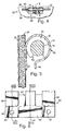
- the visor is mounted to the pivot rod 30 by an improved visor control assembly 50 as illustrated in Figs. 4-11, which not only permits the visor to slidably move along the visor rod, but also permits the storage of the visor in the position shown in Fig. 1, as well as holding the visor in any desired lowered selected use position pivoted about rod 30 or slidably adjusted therealong.
- the construction of the visor control to accomplish this is best seen by reference to Figs. 4-11, now described.
- the visor 22 is made from a relatively thin fiberboard 24 die cut in the shape of a butterfly with an upholstery material 25 (Fig. 5) surrounding its outer surface and folded over the edges.
- the butterfly-shaped core integrally includes a pair of panels which are folded along top edge 26 of the visor and suitably bonded along the mating peripheral edges after the insertion of the visor rod and control 50 of the present invention.
- This core construction and its upholstering can be of the type disclosed in greater detail in U.S. Patent No. 5,161,850.
- the visor control 50 of the present invention includes, as initially seen in Figs. 4 and 5, a tubular torque spring 60 surrounding a lubricous polymeric sleeve 70 which, in turn, is slidably mounted to the pivot rod 30.
- the pivot rod 30 is made of steel and is keyed by a flat 32 or other geometric shape to prevent the rotation of the polymeric sleeve 70.
- Sleeve 70 has an internal shape as described in greater detail below in connection with Figs. 9-11, which engages flat 32 to prevent rotation of the sleeve around the pivot rod while allowing the sleeve and torque control 50 attached to the visor body 24 to slide along pivot rod 30.
- a visor torque spring 60 Surrounding the polymeric sleeve 70 is a visor torque spring 60 which is anchored to the visor body 24 by means of suitable fasteners or by a bonding adhesive. In the case of fiberboard material employed, fasteners, such as rivets 61, extending through apertures 62 (Fig. 6) in the torque spring 60 can be employed.
- the torque spring 60 is longitudinally fixed around sleeve 70 but rotates around the outer generally cylindrical surface 71 of sleeve 70 in a controlled manner which can be selected, as described below, to allow the visor to be raised to a stored position against the headliner of the vehicle or lowered to selected use positions.
- the sleeve 70 provides a sliding interface between the visor body and rod 30 while the torque spring 60 provides the rotational adjustment of the visor about sleeve 70.
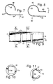
- the torque spring 60 is shown in detail in Figs. 6-8 and is now described.
- Torque spring 60 comprises a steel member having a thickness of about .05 inches and suitably treated for the automotive environment. It comprises a back wall 64 which is substantially flat and rectangular and includes a pair of apertures 62 or other fastening means for attaching the torque control in a fixed relationship to the visor body adjacent the upper edge 26, as seen in Fig. 4.
- the torque spring includes a pair of opposed end semicylindrical collars 66 and 68, which extend over the corresponding ends 76, 78 (Fig. 9) of split sleeve 70.
- the semicylindrical collars 66, 68 of torque spring 60 are roll-formed to provide an inner diameter 65 which snugly engages sleeve 70.
- the center of torque spring 60 includes a center semicylindrical adjustable collar 67 terminating in a tang 69, which extends over a center section 77 (Fig. 9) of the split sleeve 70.
- Tang 69 can be depressed downwardly in a direction indicated by arrow B in Fig. 8 to provide an adjustable and selectable rotational torque for the torque spring 60 around the outer diameter 71 of sleeve 70 and/or adjust the sliding friction between sleeve 70 and rod 30.
- the shape of the inner surface 63 of adjustable collar 67 can be changed by pressure on the tang to deform the center collar 67 to increase or decrease the desired torque depending upon the visor with which the control is employed.
- split sleeve 70 The details of the split sleeve 70 are shown in Figs. 9-11 in which the generally cylindrical outer diameter 71 of the sleeve is shown with the center collar 77 including a longitudinally extending split or opening 79 (Figs. 5 and 11) which allows the tang 69 to also adjust the sliding resistance which sleeve 70 applies to pivot rod 30.
- the end cylindrical collars 76, 78 are spaced from center split collar 77 by slots 73 and 75 formed through the cylindrical sleeve 70 and circumscribing an arc of approximately 270° of the cylindrical sleeve.
- the inner diameter 81 of sleeve 70 includes a flat 84 which engages the flat 34 on pivot rod 30 to lockably mount sleeve 70 to the pivot rod against rotation about the longitudinal axis of the rod while allowing sliding movement along the longitudinal axis of the rod.
- the cylindrical section 83 of the center adjustable collar 77 has a diameter which is selected by the gap width 79, in turn, controlled by the tang 69 of torque spring 60.
- the torque spring 60 tends to provide a higher torque in a holding direction for the visor than in a direction opposite (i.e. holding the visor against the vehicle headliner) than the raising of the visor from the lowered adjusted position.
- Sleeve 70 has a thickness of about 1/8 inch and a length along its longitudinal axis of about 2 inches.
Landscapes
- Engineering & Computer Science (AREA)
- Mechanical Engineering (AREA)
- Pivots And Pivotal Connections (AREA)
- Springs (AREA)
Abstract
Description
Claims (23)
- A sliding visor assembly comprising:a visor body;a visor pivot rod for mounting said visor body to a vehicle; anda torque control coupling said pivot rod to said visor body wherein said torque control comprises a split polymeric sleeve mounted to said pivot rod to allow said sleeve to slide along said pivot rod and including an interengaging surface preventing rotation of said sleeve around the axis of said rod, and a torque spring surrounding said sleeve and including an adjustable collar engaging said sleeve for adjusting the rotational torque of said torque spring around said polymeric sleeve and the sliding friction of said sleeve with respect to said rod.
- The visor assembly as defined in claim 1 wherein said sleeve comprises a split sleeve having a pair of generally cylindrical end collars and a center split collar isolated from said ends by slots formed into the sidewall of said sleeve.
- The visor assembly as defined in claim 3 wherein said slots circumscribe an arc of approximately 270° of said sidewall of said sleeve.
- The visor assembly as defined in claim 3 wherein said center collar of said sleeve includes a notch formed along the longitudinal axis of said sleeve to define a pair of flexible semicylindrical legs circumscribing said pivot rod.
- The visor assembly as defined in claim 4 wherein said torque spring includes a pair of semicylindrical end collars surrounding said end collars of said sleeve and a center semicylindrical collar terminating in a tang, said center collar of said spring aligned with said split collar of said sleeve and deformable in an adjustable manner to adjust the rotational torque of said torque spring around said polymeric sleeve and the pressure applied by said legs of said sleeve on said rod for adjusting the sliding friction of said sleeve along said rod.
- The visor assembly as defined in claim 5 wherein said torque spring is made of spring steel.
- A visor torque control comprising:a polymeric sleeve for mounting to a pivot rod to allow said sleeve to slide along the pivot rod and including an interengaging surface preventing rotation of said sleeve around the axis of the pivot rod, said sleeve including a section with at least one adjustable leg at lest partially surrounding said rod; anda torque spring surrounding said sleeve and including an adjustable collar engaging said leg of said sleeve for adjusting the rotational torque of said torque spring around said polymeric sleeve and the sliding friction of said sleeve with respect to the rod.
- The torque control as defined in claim 7 wherein said sleeve comprises a split sleeve having a pair of generally cylindrical end collars and a center split collar isolated from said ends by slots formed into the sidewall of said sleeve.
- The torque control as defined in claim 8 wherein said slots circumscribe an arc of approximately 270° of said sidewall of said sleeve.
- The torque control as defined in claim 9 wherein said center collar of said sleeve includes a notch formed along the longitudinal axis of said sleeve to define a pair of flexible semicylindrical legs circumscribing said pivot rod.
- The torque control as defined in claim 9 wherein said torque spring includes a pair of semicylindrical end collars surrounding said end collars of said sleeve and a center semicylindrical collar terminating in a tang, said center collar of said spring aligned with said split collar of said sleeve and deformable in an adjustable manner to adjust the rotational torque of said torque spring around said polymeric sleeve and the pressure applied by said legs of said sleeve on said rod for adjusting the sliding friction of said sleeve along said rod.
- The torque control as defined in claim 11 wherein said torque spring is made of spring steel.
- The torque control as defined in claim 12 wherein said polymeric sleeve is made of Delrin®.
- A visor control comprising:a pivot rod having a flat formed thereon;a polymeric sleeve mounted to said pivot rod to allow said sleeve to slide along said pivot rod and including an interengaging surface engaging said flat for preventing rotation of said sleeve around the axis of said rod, said sleeve including a pair of spaced end collars extending around said rod and a center collar having at least one movable leg at lest partially surrounding said rod; anda torque spring surrounding said sleeve and including an adjustable collar engaging said leg of said sleeve for adjusting the rotational torque of said torque spring around said polymeric sleeve and the sliding friction of said sleeve with respect to said rod.
- The visor control as defined in claim 14 wherein said sleeve comprises a laterally split sleeve defining said end collars which are generally cylindrical and said center collar which is longitudinally split and isolated from said end collars by slots formed into the sidewall of said sleeve.
- The visor control as defined in claim 15 wherein said slots circumscribe an arc of approximately 270° of said sidewall of said sleeve.
- The visor control as defined in claim 16 wherein said center collar of said sleeve includes a notch formed along the longitudinal axis of said sleeve to define a pair of flexible semicylindrical legs circumscribing said pivot rod.
- The visor control as defined in claim 16 wherein said torque spring includes a pair of semicylindrical end collars surrounding said end collars of said sleeve and a center semicylindrical collar terminating in a tang, said center collar of said spring aligned with said center collar of said sleeve and deformable in an adjustable manner to adjust the rotational torque of said torque spring around said polymeric sleeve and the pressure applied by said legs of said sleeve on said rod for adjusting the sliding friction of said sleeve along said rod.
- The visor control as defined in claim 18 wherein said torque spring is made of spring steel.
- The visor control as defined in claim 19 wherein said polymeric sleeve is made of Delrin®.
- The visor control as defined in claim 14 wherein said sleeve has a thickness of about 1/8 inch.
- The visor control as defined in claim 21 wherein said sleeve has a length of about 2 inches.
- The visor control as defined in claim 14 wherein said torque spring is made of spring steel having a thickness of about .05 inch.
Applications Claiming Priority (2)
| Application Number | Priority Date | Filing Date | Title |
|---|---|---|---|
| US08/826,432 US5967587A (en) | 1997-03-18 | 1997-03-18 | Sliding visor |
| US826432 | 1997-03-18 |
Publications (3)
| Publication Number | Publication Date |
|---|---|
| EP0865947A2 true EP0865947A2 (en) | 1998-09-23 |
| EP0865947A3 EP0865947A3 (en) | 1999-04-07 |
| EP0865947B1 EP0865947B1 (en) | 2002-07-03 |
Family
ID=25246529
Family Applications (1)
| Application Number | Title | Priority Date | Filing Date |
|---|---|---|---|
| EP98302053A Expired - Lifetime EP0865947B1 (en) | 1997-03-18 | 1998-03-18 | Sliding visor |
Country Status (5)
| Country | Link |
|---|---|
| US (1) | US5967587A (en) |
| EP (1) | EP0865947B1 (en) |
| JP (1) | JPH10278579A (en) |
| CA (1) | CA2226351A1 (en) |
| DE (1) | DE69806289T2 (en) |
Cited By (1)
| Publication number | Priority date | Publication date | Assignee | Title |
|---|---|---|---|---|
| US6659528B1 (en) | 2002-09-18 | 2003-12-09 | Lear Corporation | Method and apparatus for sliding and rotating a vehicle sun visor |
Families Citing this family (38)
| Publication number | Priority date | Publication date | Assignee | Title |
|---|---|---|---|---|
| US6296293B1 (en) * | 2000-04-28 | 2001-10-02 | Lear Corporation | Slidable auxiliary sun visor assembly |
| US6328370B1 (en) * | 2000-08-29 | 2001-12-11 | Sang R. Kim | Horizontally and vertically positionable sun visor |
| DE10222898A1 (en) * | 2001-06-11 | 2002-12-19 | Klingelhoefer Jost | Door hinge for vehicle door has integrated brake and comprises separate bush lining bore in hinge eye and having stepped decreasing diameter |
| TW508040U (en) * | 2001-09-05 | 2002-10-21 | Hinge Basestrong Co Ltd | Radial pressing structure of rotation shaft |
| KR20020035046A (en) * | 2002-03-14 | 2002-05-09 | 이육권 | Device of hinge for electrical maachchinery |
| US20040134033A1 (en) * | 2002-07-29 | 2004-07-15 | Aaron Raines | Friction hinge assembly for a mirror of a display unit |
| DE10306733B4 (en) * | 2003-02-17 | 2005-08-18 | Johnson Controls Interiors Gmbh & Co. Kg | Device for locking, body and arrangement |
| CA2472829C (en) * | 2003-07-08 | 2012-04-24 | Cooper Technologies Company | Fuse with metallic state indicator |
| US20050073168A1 (en) * | 2003-10-01 | 2005-04-07 | Gerardo Herrera | Visor gap shade |
| US20050125950A1 (en) * | 2003-12-10 | 2005-06-16 | Ding-Hone Su | Hinge with a rotating function |
| US7556759B2 (en) * | 2004-01-29 | 2009-07-07 | Hiemstra David L | Auto-indexing visor core |
| US6910725B1 (en) | 2004-02-11 | 2005-06-28 | Innotec Corporation | Sliding visor |
| US7152901B2 (en) * | 2004-10-22 | 2006-12-26 | Innotec Corporation | Vehicle visor construction and method |
| US7055884B2 (en) * | 2004-10-25 | 2006-06-06 | Lear Corporation | Low-friction sleeve insert for a visor bearing |
| US7537263B2 (en) | 2006-10-17 | 2009-05-26 | Delphia John B | Visor assembly for a vehicle |
| TW200833935A (en) * | 2007-02-06 | 2008-08-16 | Mitac Technology Corp | Engaging type socket structure of hinge |
| US7818907B1 (en) | 2008-03-14 | 2010-10-26 | Warrington Jr Frank E | Ornamental sun visor cover |
| US7963582B2 (en) * | 2008-10-18 | 2011-06-21 | Irvin Automotive Products, Inc. | Sliding visor |
| JP2011196015A (en) * | 2010-03-17 | 2011-10-06 | Nifco Inc | Slide assist device |
| JP5433466B2 (en) * | 2010-03-17 | 2014-03-05 | 株式会社ニフコ | Sliding assist device |
| US9022438B2 (en) | 2012-09-14 | 2015-05-05 | Honda Motor Co., Ltd. | Cap assembly for vehicle |
| US9816537B2 (en) | 2013-02-27 | 2017-11-14 | Woodward, Inc. | Rotary piston type actuator with a central actuation assembly |
| US9234535B2 (en) | 2013-02-27 | 2016-01-12 | Woodward, Inc. | Rotary piston type actuator |
| US9163648B2 (en) | 2013-02-27 | 2015-10-20 | Woodward, Inc. | Rotary piston type actuator with a central actuation assembly |
| US9631645B2 (en) * | 2013-02-27 | 2017-04-25 | Woodward, Inc. | Rotary piston actuator anti-rotation configurations |
| US10737559B2 (en) | 2014-12-16 | 2020-08-11 | Irvin Automotive Products, LLC | Visor |
| US9404300B1 (en) * | 2015-04-28 | 2016-08-02 | Wayne W. Ramsdell | Hinge and applications thereof |
| US10428565B1 (en) | 2015-04-28 | 2019-10-01 | Wayne W. Ramsdell | Hinge and applications thereof |
| US9828795B1 (en) | 2015-04-28 | 2017-11-28 | Wayne W. Ramsdell | Hinge and applications thereof |
| US11530560B1 (en) | 2015-04-28 | 2022-12-20 | Wayne W. Ramsdell | Hinge and applications thereof |
| US10344511B2 (en) * | 2016-10-21 | 2019-07-09 | Hewlett-Packard Development Company, L.P. | Hinge damper |
| US10081228B2 (en) * | 2016-11-08 | 2018-09-25 | Mahmoud Razzaghi | Car visor |
| TWI718460B (en) * | 2017-12-26 | 2021-02-11 | 仁寶電腦工業股份有限公司 | Hinge structure |
| US10688850B2 (en) | 2018-03-13 | 2020-06-23 | Irvin Automotive Products, LLC | Sliding visor |
| US10870337B2 (en) | 2019-02-28 | 2020-12-22 | Irvin Automotive Products, LLC | Thin visor |
| US10864804B2 (en) | 2019-02-28 | 2020-12-15 | Irvin Automotive Products, LLC | Sliding thin visor |
| US11199248B2 (en) | 2019-04-30 | 2021-12-14 | Woodward, Inc. | Compact linear to rotary actuator |
| WO2021207482A1 (en) | 2020-04-08 | 2021-10-14 | Woodward, Inc. | Rotary piston type actuator with a central actuation assembly |
Citations (5)
| Publication number | Priority date | Publication date | Assignee | Title |
|---|---|---|---|---|
| US4925233A (en) | 1987-12-28 | 1990-05-15 | Prince Corporation | Adjustable visor |
| US4998765A (en) | 1989-02-21 | 1991-03-12 | Prince Corporation | Sliding visor |
| US5161850A (en) | 1991-09-10 | 1992-11-10 | Prince Corporation | Sliding visor |
| US5409285A (en) | 1994-04-18 | 1995-04-25 | Prince Corporation | Sliding visor |
| US5653490A (en) | 1996-04-12 | 1997-08-05 | Prince Corporation | Sliding visor |
Family Cites Families (20)
| Publication number | Priority date | Publication date | Assignee | Title |
|---|---|---|---|---|
| US1625510A (en) * | 1924-10-14 | 1927-04-19 | Winchester Repeating Arms Co | Telescopic fishing rod |
| US2340015A (en) * | 1940-06-19 | 1944-01-25 | Woodall Industries Inc | Visor construction |
| US2322898A (en) * | 1942-01-22 | 1943-06-29 | William C Van Dresser | Visor structure |
| US2462304A (en) * | 1946-07-18 | 1949-02-22 | Jacobs Co F L | Sun visor |
| US2596397A (en) * | 1948-10-27 | 1952-05-13 | Woodall Industries Inc | Sun visor |
| DE1630343A1 (en) * | 1967-08-25 | 1971-05-13 | Daimler Benz Ag | Sun visors, in particular on the windshield of motor vehicles |
| GB1354485A (en) * | 1970-05-18 | 1974-06-05 | Chrysler Uk | Sunvisors for vehicles |
| US3765054A (en) * | 1971-06-02 | 1973-10-16 | Wall & Leigh Thermoplastics | Frictional connecting devices |
| SE7507284L (en) * | 1975-06-25 | 1976-12-26 | Harry Lilja | SUN PROTECTION PROVIDED FOR MOTOR VEHICLES |
| CH609754A5 (en) * | 1977-05-05 | 1979-03-15 | Nationale Sa | |
| JPS57140222A (en) * | 1981-02-26 | 1982-08-30 | Nissan Motor Co Ltd | Sun visor |
| DE3261939D1 (en) * | 1981-06-19 | 1985-02-28 | Nissan Motor | Hinge structure for a sun visor or the like |
| US4489974A (en) * | 1982-09-27 | 1984-12-25 | Warhol John G | Visor assembly including friction mount |
| DE3345764C1 (en) * | 1983-12-17 | 1985-06-20 | Daimler-Benz Ag, 7000 Stuttgart | Sun visor for vehicles |
| US4620742A (en) * | 1984-11-21 | 1986-11-04 | Irvin Industries Inc. | Visor detent |
| US4964193A (en) * | 1987-04-21 | 1990-10-23 | E. R. Wagner Manufacturing Company | Hinge |
| US5044687A (en) * | 1988-02-22 | 1991-09-03 | Abu Shumays Ibrahim K | Slidable sun visors for automobiles |
| US5491874A (en) * | 1993-06-02 | 1996-02-20 | Cema Technologies, Inc. | Hinge assembly |
| US5645308A (en) * | 1995-08-29 | 1997-07-08 | Prince Corporation | Sliding visor |
| US5820197A (en) * | 1997-04-11 | 1998-10-13 | Prince Corporation | Visor torque control |
-
1997
- 1997-03-18 US US08/826,432 patent/US5967587A/en not_active Expired - Fee Related
-
1998
- 1998-02-11 CA CA002226351A patent/CA2226351A1/en not_active Abandoned
- 1998-03-02 JP JP10063892A patent/JPH10278579A/en active Pending
- 1998-03-18 DE DE69806289T patent/DE69806289T2/en not_active Expired - Fee Related
- 1998-03-18 EP EP98302053A patent/EP0865947B1/en not_active Expired - Lifetime
Patent Citations (5)
| Publication number | Priority date | Publication date | Assignee | Title |
|---|---|---|---|---|
| US4925233A (en) | 1987-12-28 | 1990-05-15 | Prince Corporation | Adjustable visor |
| US4998765A (en) | 1989-02-21 | 1991-03-12 | Prince Corporation | Sliding visor |
| US5161850A (en) | 1991-09-10 | 1992-11-10 | Prince Corporation | Sliding visor |
| US5409285A (en) | 1994-04-18 | 1995-04-25 | Prince Corporation | Sliding visor |
| US5653490A (en) | 1996-04-12 | 1997-08-05 | Prince Corporation | Sliding visor |
Cited By (4)
| Publication number | Priority date | Publication date | Assignee | Title |
|---|---|---|---|---|
| US6659528B1 (en) | 2002-09-18 | 2003-12-09 | Lear Corporation | Method and apparatus for sliding and rotating a vehicle sun visor |
| GB2393213A (en) * | 2002-09-18 | 2004-03-24 | Lear Corp | Vehicle Sun Visor Mounting Assembly |
| GB2393213B (en) * | 2002-09-18 | 2004-07-21 | Lear Corp | Method and apparatus for sliding and rotating a vehicle sun visor |
| DE10301660B4 (en) * | 2002-09-18 | 2005-06-23 | Lear Corp., Southfield | Device for moving and rotating a vehicle sun visor |
Also Published As
| Publication number | Publication date |
|---|---|
| JPH10278579A (en) | 1998-10-20 |
| CA2226351A1 (en) | 1998-09-20 |
| US5967587A (en) | 1999-10-19 |
| EP0865947B1 (en) | 2002-07-03 |
| EP0865947A3 (en) | 1999-04-07 |
| DE69806289D1 (en) | 2002-08-08 |
| DE69806289T2 (en) | 2003-02-20 |
Similar Documents
| Publication | Publication Date | Title |
|---|---|---|
| EP0865947B1 (en) | Sliding visor | |
| US5653490A (en) | Sliding visor | |
| CA1275844C (en) | Visor system | |
| US5645308A (en) | Sliding visor | |
| US4925233A (en) | Adjustable visor | |
| US5004289A (en) | Visor torque control | |
| US5409285A (en) | Sliding visor | |
| EP1007381B1 (en) | Snap-in mount | |
| USRE39316E1 (en) | Sliding visor | |
| EP0938991B1 (en) | Sliding visor assembly | |
| US4690450A (en) | Visor system | |
| US5871252A (en) | Telescopic sunvisor | |
| US5820197A (en) | Visor torque control | |
| US20040068839A1 (en) | Vehicle sunshade guide mechanism | |
| CA1291190C (en) | Visor | |
| US5967588A (en) | Visor control | |
| US4762359A (en) | Visor system | |
| US5328227A (en) | Extendable pivoted visor panel | |
| JPH06297946A (en) | Sunvisor for use on vehicle | |
| US5071186A (en) | Visor | |
| US5765899A (en) | Lockable sliding visor | |
| US5431473A (en) | Mirror cover and visor extender | |
| US5529367A (en) | Visor with sliding pivot mount | |
| US5810421A (en) | Multiple function visor | |
| US6719352B2 (en) | Visor mounting assembly |
Legal Events
| Date | Code | Title | Description |
|---|---|---|---|
| PUAI | Public reference made under article 153(3) epc to a published international application that has entered the european phase |
Free format text: ORIGINAL CODE: 0009012 |
|
| AK | Designated contracting states |
Kind code of ref document: A2 Designated state(s): DE FR GB |
|
| AX | Request for extension of the european patent |
Free format text: AL;LT;LV;MK;RO;SI |
|
| PUAL | Search report despatched |
Free format text: ORIGINAL CODE: 0009013 |
|
| AK | Designated contracting states |
Kind code of ref document: A3 Designated state(s): AT BE CH DE DK ES FI FR GB GR IE IT LI LU MC NL PT SE |
|
| AX | Request for extension of the european patent |
Free format text: AL;LT;LV;MK;RO;SI |
|
| 17P | Request for examination filed |
Effective date: 19991005 |
|
| AKX | Designation fees paid |
Free format text: DE FR GB |
|
| 17Q | First examination report despatched |
Effective date: 20001212 |
|
| GRAG | Despatch of communication of intention to grant |
Free format text: ORIGINAL CODE: EPIDOS AGRA |
|
| GRAG | Despatch of communication of intention to grant |
Free format text: ORIGINAL CODE: EPIDOS AGRA |
|
| GRAH | Despatch of communication of intention to grant a patent |
Free format text: ORIGINAL CODE: EPIDOS IGRA |
|
| GRAH | Despatch of communication of intention to grant a patent |
Free format text: ORIGINAL CODE: EPIDOS IGRA |
|
| GRAA | (expected) grant |
Free format text: ORIGINAL CODE: 0009210 |
|
| AK | Designated contracting states |
Kind code of ref document: B1 Designated state(s): DE FR GB |
|
| REF | Corresponds to: |
Ref document number: 69806289 Country of ref document: DE Date of ref document: 20020808 |
|
| ET | Fr: translation filed | ||
| PLBE | No opposition filed within time limit |
Free format text: ORIGINAL CODE: 0009261 |
|
| STAA | Information on the status of an ep patent application or granted ep patent |
Free format text: STATUS: NO OPPOSITION FILED WITHIN TIME LIMIT |
|
| 26N | No opposition filed |
Effective date: 20030404 |
|
| PGFP | Annual fee paid to national office [announced via postgrant information from national office to epo] |
Ref country code: FR Payment date: 20040209 Year of fee payment: 7 |
|
| PGFP | Annual fee paid to national office [announced via postgrant information from national office to epo] |
Ref country code: GB Payment date: 20040212 Year of fee payment: 7 |
|
| PGFP | Annual fee paid to national office [announced via postgrant information from national office to epo] |
Ref country code: DE Payment date: 20040331 Year of fee payment: 7 |
|
| REG | Reference to a national code |
Ref country code: GB Ref legal event code: 732E |
|
| PG25 | Lapsed in a contracting state [announced via postgrant information from national office to epo] |
Ref country code: GB Free format text: LAPSE BECAUSE OF NON-PAYMENT OF DUE FEES Effective date: 20050318 |
|
| PG25 | Lapsed in a contracting state [announced via postgrant information from national office to epo] |
Ref country code: DE Free format text: LAPSE BECAUSE OF NON-PAYMENT OF DUE FEES Effective date: 20051001 |
|
| GBPC | Gb: european patent ceased through non-payment of renewal fee |
Effective date: 20050318 |
|
| PG25 | Lapsed in a contracting state [announced via postgrant information from national office to epo] |
Ref country code: FR Free format text: LAPSE BECAUSE OF NON-PAYMENT OF DUE FEES Effective date: 20051130 |
|
| REG | Reference to a national code |
Ref country code: FR Ref legal event code: ST Effective date: 20051130 |