EP0865969A2 - Toiture amovible pour une plate-forme de chargement d'un véhicule, en particulier pour une fourgonnette - Google Patents
Toiture amovible pour une plate-forme de chargement d'un véhicule, en particulier pour une fourgonnette Download PDFInfo
- Publication number
- EP0865969A2 EP0865969A2 EP98101708A EP98101708A EP0865969A2 EP 0865969 A2 EP0865969 A2 EP 0865969A2 EP 98101708 A EP98101708 A EP 98101708A EP 98101708 A EP98101708 A EP 98101708A EP 0865969 A2 EP0865969 A2 EP 0865969A2
- Authority
- EP
- European Patent Office
- Prior art keywords
- winding shaft
- separating device
- pawl
- loading space
- disc
- Prior art date
- Legal status (The legal status is an assumption and is not a legal conclusion. Google has not performed a legal analysis and makes no representation as to the accuracy of the status listed.)
- Granted
Links
- 238000004804 winding Methods 0.000 claims abstract description 55
- 239000000463 material Substances 0.000 claims abstract description 32
- 238000005096 rolling process Methods 0.000 claims abstract description 7
- 230000033001 locomotion Effects 0.000 claims description 10
- 230000008878 coupling Effects 0.000 claims description 5
- 238000010168 coupling process Methods 0.000 claims description 5
- 238000005859 coupling reaction Methods 0.000 claims description 5
- 230000000903 blocking effect Effects 0.000 claims description 4
- 238000000926 separation method Methods 0.000 description 6
- 241001422033 Thestylus Species 0.000 description 2
- 230000006835 compression Effects 0.000 description 2
- 238000007906 compression Methods 0.000 description 2
- 239000004753 textile Substances 0.000 description 2
- 229910000831 Steel Inorganic materials 0.000 description 1
- 230000004323 axial length Effects 0.000 description 1
- 238000010276 construction Methods 0.000 description 1
- 230000018109 developmental process Effects 0.000 description 1
- 239000004744 fabric Substances 0.000 description 1
- 239000011888 foil Substances 0.000 description 1
- 238000000034 method Methods 0.000 description 1
- 230000000149 penetrating effect Effects 0.000 description 1
- 230000002093 peripheral effect Effects 0.000 description 1
- 238000003825 pressing Methods 0.000 description 1
- 239000000523 sample Substances 0.000 description 1
- 239000010959 steel Substances 0.000 description 1
Images


Classifications
-
- B—PERFORMING OPERATIONS; TRANSPORTING
- B60—VEHICLES IN GENERAL
- B60R—VEHICLES, VEHICLE FITTINGS, OR VEHICLE PARTS, NOT OTHERWISE PROVIDED FOR
- B60R5/00—Compartments within vehicle body primarily intended or sufficiently spacious for trunks, suit-cases, or the like
- B60R5/04—Compartments within vehicle body primarily intended or sufficiently spacious for trunks, suit-cases, or the like arranged at rear of vehicle
- B60R5/044—Compartments within vehicle body primarily intended or sufficiently spacious for trunks, suit-cases, or the like arranged at rear of vehicle luggage covering means, e.g. parcel shelves
- B60R5/045—Compartments within vehicle body primarily intended or sufficiently spacious for trunks, suit-cases, or the like arranged at rear of vehicle luggage covering means, e.g. parcel shelves collapsible or transformable
- B60R5/047—Compartments within vehicle body primarily intended or sufficiently spacious for trunks, suit-cases, or the like arranged at rear of vehicle luggage covering means, e.g. parcel shelves collapsible or transformable collapsible by rolling-up
Definitions
- the invention relates to a cargo space separation device for motor vehicles, especially for combination passenger cars according to the preamble of the claim 1.
- a load compartment separating device is in described in DE 27 49 560 A1.
- the form locking mechanism contains locking teeth that lock in the direction of rotation load-bearing locking disc, which with a Sheet steel spring forming pawl cooperates.
- One end of the pawl is fixed in the vehicle side Clamp of the cargo hold separation device clamped, while the free end of the pawl is one Manual actuation approach forms.
- the material web for example as textile, foil or net-like material web formed
- the pawl it is necessary to insert the pawl into its To move the release position out of engagement with the locking disc. This can be done in that during the Rolling of the material web the pawl constantly from Hand is pressed into its release position.
- the cargo space divider at both ends of the Winding shaft has a form locking, would such an arrangement for an additional operator Require handling of the cargo compartment divider.
- the invention is the Task based on the well-known load compartment separation device to develop so that this is a convenient and one at the same time the safety needs of the vehicle occupants appropriate operation allowed.
- the actuator with the winding shaft at least indirectly by friction has an actuator coupled for rotary driving, which with a secondary friction surface against one with of the winding shaft presses the non-rotatable primary friction surface and when the winding shaft unwinds, the pawl in their release position.
- the cargo space separation device allows following advantageous mode of operation:
- the actuator due to friction clutch from the winding shaft itself or from one with the winding shaft moving component and used this movement to pawl in to displace their release position.
- the Rolling movement becomes the release position of the pawl maintained by friction. Only with one Backward movement of the material web in the winding direction the winding shaft gives the actuator the Pawl free, so that it is back in its locked position returns.
- the winding shaft is against Rolling rotation secured while the free end area the material web releasably fixed on the vehicle side is.
- a flameproof motion coupling between actuator and pawl provided. This means that the actuator, or vice versa the pawl, each in one direction of motion independently of the other Component is.
- the actuator for the pressure-resistant motion coupling with the pawl one in its release position has pressing actuating cams.
- a preferred embodiment according to the invention which allows a compact design is characterized by that the actuator is coaxial with Winding shaft mounted, rotatable relative to the winding shaft, the friction disc having the secondary friction surface is.
- An actuation of the load compartment separating device is that the pawl on a probe shaft extending axially parallel to the winding shaft is rotatably arranged, which one on the Winding the rolled-up material web on the outside Touch finger carries that at a certain material web winding thickness the pawl is disengaged offset with the locking disc.
- This embodiment of the invention is therefore particularly advantageous because first one in each Trap material length required to secure the load is to be handled without a Backward movement of the material web in the winding direction the pawl are moved to their locked position can.
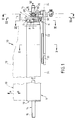
- the cargo space separating device 10 has a winding shaft 11, whose tubular winding jacket 12 a dash of material 13 shown in dashed lines.
- the material web 13 can be a textile, foil-like or net-like fabrics act.
- the position of the winding shaft 11 in the room is arbitrary.
- the winding jacket 12 is axial from the latter completely penetrating shaft body 14 worn and connected to it in a rotationally fixed manner. Owned at one end the shaft body 14 has a keyway 15, which for non-rotatable Connection with a motor, not shown Drive, for example with a spring motor, serves.
- the unwinding or extending direction of the material web 13 is designated A during the winding or winding direction the material web 13 designated B. is.
- the material web 13 is otherwise in a welt groove 16 of the tubular winding jacket 12 held.
- Locking teeth R On one end of the shaft body 14 is an asymmetrical one Locking teeth R having locking teeth 17 rotatably arranged.
- Each locking tooth 17 has a sliding flank 18 and a blocking edge 19.
- the shaft body 14 provided with axially short deformation ribs 20, about which during assembly (according to FIG. 7 from right to left) a friction disc F axially pushed away and after passing the deformation ribs 20 by about 90 ° can be twisted.
- the deformation ribs 20 an axial lock for the friction disc F is for this purpose, the friction disc F with a Bearing opening 21 provided, which on diametrically opposite Places supplemented by recesses 22 which corresponds to the space requirement of the deformation ribs 20 correspond.
- the stops 23, which are only indicated in FIG. 7, 24 of the friction disc F provide in connection with a not shown bracket-side counterstop for the fact that the friction disc F is on its pivot bearing area 25 relative only over a limited circumferential angle can turn to the locking disc R.
- This circumferential angle of e.g. 20 ° stands for the circumferential angle in a relationship that they are about Fig. 4 apparent control curve 26 which due to a peripheral recess in the circular friction disc F is formed and which at one end includes a control or actuation cam 27.
- the friction disc F is along the one marked x Double arrow on their pivot bearing area 25 on the Shaft body 14 is axially movable minimally, however by means of a helical compression spring 28 only indicated, which is supported on an abutment 29 with a sufficient normal force against the radially extending and outward facing face of the Locking washer R pressed in direction N.
- the friction disc F is only indicated in FIG. 1 provided annular collar 30, which with its end face facing the locking disk R. forms a secondary friction surface S by the Helical compression spring 28 in the direction N against that of the Front side of the locking disc R formed primary friction surface P is pressed.
- the winding shaft 11 rotates with its winding jacket 12 in the unwinding direction u.
- the stylus finger 33 holds the stylus shaft 32 in such a position that the pawl K arranged in a rotationally fixed manner on the pushbutton shaft 32 is in its release position (cf. FIGS. 3 and 4).
- the pawl side is in the locked position Blocking surface 36 on the blocking edge 19 of the relevant Ratchet tooth 17. This is the material web 13 locked in the rolling direction u and thus on the Winding shaft 11 secured.
- the pin 40 can also be used instead of the one shown in FIG. 7 Stops 23, 24 the function of a rotation limit the friction disc F to a circumferential angle of e.g. Meet 20 ° by the pin 40 a fixed space circular kidney-shaped slot slot passes through, which extends over the circumferential angle of e.g. 20 ° extends.
- this has a pin 43, which from a towing eye 41 a Pull handle 42 is overlapped. If the pull handle 42 is pulled in the direction y, so the Friction disc F rotated in the direction of roll rotation u and thus the pawl K - as already described - in their release position.
Landscapes
- Engineering & Computer Science (AREA)
- Mechanical Engineering (AREA)
- Vehicle Step Arrangements And Article Storage (AREA)
- Lock And Its Accessories (AREA)
- Winding Of Webs (AREA)
Applications Claiming Priority (2)
| Application Number | Priority Date | Filing Date | Title |
|---|---|---|---|
| DE19710786 | 1997-03-17 | ||
| DE1997110786 DE19710786C1 (de) | 1997-03-17 | 1997-03-17 | Laderaum-Trennvorrichtung für Kraftwagen, insbesondere für Kombinations-Personenkraftwagen |
Publications (3)
| Publication Number | Publication Date |
|---|---|
| EP0865969A2 true EP0865969A2 (fr) | 1998-09-23 |
| EP0865969A3 EP0865969A3 (fr) | 2001-05-09 |
| EP0865969B1 EP0865969B1 (fr) | 2003-10-08 |
Family
ID=7823479
Family Applications (1)
| Application Number | Title | Priority Date | Filing Date |
|---|---|---|---|
| EP19980101708 Expired - Lifetime EP0865969B1 (fr) | 1997-03-17 | 1998-02-02 | Toiture amovible pour une plate-forme de chargement d'un véhicule, en particulier pour une fourgonnette |
Country Status (3)
| Country | Link |
|---|---|
| EP (1) | EP0865969B1 (fr) |
| DE (1) | DE19710786C1 (fr) |
| ES (1) | ES2208977T3 (fr) |
Cited By (1)
| Publication number | Priority date | Publication date | Assignee | Title |
|---|---|---|---|---|
| CN106184039A (zh) * | 2015-04-29 | 2016-12-07 | 长城汽车股份有限公司 | 行李箱盖板开度的调节机构及其棘轮 |
Families Citing this family (4)
| Publication number | Priority date | Publication date | Assignee | Title |
|---|---|---|---|---|
| DE10127463B4 (de) * | 2001-06-07 | 2004-05-06 | Peter Butz Gmbh & Co Verwaltungs-Kg | Sicherheitseinrichtung für Fahrzeuge |
| DE102009048513B4 (de) * | 2009-10-07 | 2011-06-22 | HS Genion GmbH Engineering Services, 82205 | Laderaumabtrennung |
| DE102010014801A1 (de) | 2010-04-07 | 2011-10-13 | Bos Gmbh & Co. Kg | Schutzvorrichtung für einen Fahrzeuginnenraum |
| DE102012023610B4 (de) * | 2012-12-04 | 2025-12-18 | Günter Bauregger | Rolleinrichtung eines Seitenverdecks eines Lastfahrzeuges und Verfahren zur Steuerung des Rollvorganges |
Citations (1)
| Publication number | Priority date | Publication date | Assignee | Title |
|---|---|---|---|---|
| DE2749560A1 (de) | 1977-11-05 | 1979-05-10 | Eugen Seitz | Vorrichtung zum abteilen des hinteren laderaumes vom fahrgastraum eines fuer den transport von personen und lasten ausgelegten kraftfahrzeuges (kombifahrzeug) |
Family Cites Families (1)
| Publication number | Priority date | Publication date | Assignee | Title |
|---|---|---|---|---|
| DE29704725U1 (de) * | 1997-03-17 | 1997-07-24 | Peter Butz Gmbh & Co Verwaltungs-Kg, 40764 Langenfeld | Laderaum-Trennvorrichtung für Kraftwagen, insbesondere für Kombinations-Personenkraftwagen |
-
1997
- 1997-03-17 DE DE1997110786 patent/DE19710786C1/de not_active Expired - Fee Related
-
1998
- 1998-02-02 ES ES98101708T patent/ES2208977T3/es not_active Expired - Lifetime
- 1998-02-02 EP EP19980101708 patent/EP0865969B1/fr not_active Expired - Lifetime
Patent Citations (1)
| Publication number | Priority date | Publication date | Assignee | Title |
|---|---|---|---|---|
| DE2749560A1 (de) | 1977-11-05 | 1979-05-10 | Eugen Seitz | Vorrichtung zum abteilen des hinteren laderaumes vom fahrgastraum eines fuer den transport von personen und lasten ausgelegten kraftfahrzeuges (kombifahrzeug) |
Cited By (2)
| Publication number | Priority date | Publication date | Assignee | Title |
|---|---|---|---|---|
| CN106184039A (zh) * | 2015-04-29 | 2016-12-07 | 长城汽车股份有限公司 | 行李箱盖板开度的调节机构及其棘轮 |
| CN106184039B (zh) * | 2015-04-29 | 2019-01-29 | 长城汽车股份有限公司 | 行李箱盖板开度的调节机构及其棘轮 |
Also Published As
| Publication number | Publication date |
|---|---|
| EP0865969A3 (fr) | 2001-05-09 |
| DE19710786C1 (de) | 1998-05-07 |
| ES2208977T3 (es) | 2004-06-16 |
| EP0865969B1 (fr) | 2003-10-08 |
Similar Documents
| Publication | Publication Date | Title |
|---|---|---|
| EP2921747B1 (fr) | Agencement de frein de stationnement pour boîte de vitesses de véhicule automobile | |
| DE3875449T2 (de) | Verriegelungsvorrichtung fuer einen schalthebel. | |
| EP2927540B1 (fr) | Système de frein de stationnement pour une boîte de vitesses de véhicule et boîte de vitesses en étant équipée | |
| EP1759130B1 (fr) | Systeme de frein de stationnement | |
| DE112020005457T5 (de) | Aktuator für eine Feststellbremse | |
| DE2641582A1 (de) | Gelenkbeschlag fuer fahrzeugsitze mit in bezug auf das sitzteil schwenkbarer rueckenlehne | |
| DE3827418C2 (fr) | ||
| DE102022118002A1 (de) | Verschluss-Verriegelungsanordnung mit Multi-Funktions-Kraft-Aktuator miteinzelnem Motor | |
| EP0737606A1 (fr) | Enrouleur de ceinture pour un système de ceinture de sécurité de véhicule | |
| DE69408741T2 (de) | Türverriegelungssystem für Fahrzeuge | |
| DE29908959U1 (de) | Kupplungsmechanismus | |
| DE4325693C2 (de) | Türschließeinrichtung | |
| EP4130518A2 (fr) | Verrouillage de boîte de vitesses destiné à l'aide au stationnement | |
| DE4311201C2 (de) | Sicherheitsgurtaufroller mit Klemmvorrichtung | |
| EP0914989B1 (fr) | Dispositif de sécurité pour véhicules automobiles, en particulier couvercle pour le compartiment à bagages d'un véhicule break ou similaire | |
| EP0865969B1 (fr) | Toiture amovible pour une plate-forme de chargement d'un véhicule, en particulier pour une fourgonnette | |
| DE2703972A1 (de) | Freilaufeinrichtung | |
| EP3669848B1 (fr) | Système de retenue de rétracteur, procédé et utilisation d'un tel système de retenue de rétracteur, en particulier permettant de fixer des fauteuils roulants dans des véhicules | |
| DE4210403C2 (de) | Deckelverriegelungsvorrichtung | |
| DE4111870A1 (de) | Kupplungsvorrichtung fuer automatische papiervorschubvorrichtung | |
| EP0861758B1 (fr) | Dispositif de séparation de compartiment à bagages pour voitures automobiles, en particulier pour breaks | |
| WO2005058634A1 (fr) | Siege commande par un moteur pour le pivotement du dossier, et procede correspondant | |
| DE10161647B4 (de) | Kfz-Sicherheitseinrichtung, insbesondere Laderaumabdeckung | |
| DE29704725U1 (de) | Laderaum-Trennvorrichtung für Kraftwagen, insbesondere für Kombinations-Personenkraftwagen | |
| DE69414962T2 (de) | Freie Drehung-Steuerungsvorrichtung für ein Hebe- und Zuggerät |
Legal Events
| Date | Code | Title | Description |
|---|---|---|---|
| PUAI | Public reference made under article 153(3) epc to a published international application that has entered the european phase |
Free format text: ORIGINAL CODE: 0009012 |
|
| AK | Designated contracting states |
Kind code of ref document: A2 Designated state(s): DE ES FR GB IT SE |
|
| AX | Request for extension of the european patent |
Free format text: AL;LT;LV;MK;RO;SI |
|
| PUAL | Search report despatched |
Free format text: ORIGINAL CODE: 0009013 |
|
| AK | Designated contracting states |
Kind code of ref document: A3 Designated state(s): AT BE CH DE DK ES FI FR GB GR IE IT LI LU MC NL PT SE |
|
| AX | Request for extension of the european patent |
Free format text: AL;LT;LV;MK;RO;SI |
|
| 17P | Request for examination filed |
Effective date: 20010327 |
|
| AKX | Designation fees paid |
Free format text: DE ES FR GB IT SE |
|
| GRAH | Despatch of communication of intention to grant a patent |
Free format text: ORIGINAL CODE: EPIDOS IGRA |
|
| GRAS | Grant fee paid |
Free format text: ORIGINAL CODE: EPIDOSNIGR3 |
|
| RBV | Designated contracting states (corrected) |
Designated state(s): ES FR GB IT |
|
| GRAA | (expected) grant |
Free format text: ORIGINAL CODE: 0009210 |
|
| REG | Reference to a national code |
Ref country code: DE Ref legal event code: 8566 |
|
| AK | Designated contracting states |
Kind code of ref document: B1 Designated state(s): ES FR GB IT |
|
| REG | Reference to a national code |
Ref country code: GB Ref legal event code: FG4D Free format text: NOT ENGLISH |
|
| RAP2 | Party data changed (patent owner data changed or rights of a patent transferred) |
Owner name: BOS GMBH & CO. KG |
|
| GBT | Gb: translation of ep patent filed (gb section 77(6)(a)/1977) |
Effective date: 20040107 |
|
| ET | Fr: translation filed | ||
| REG | Reference to a national code |
Ref country code: ES Ref legal event code: FG2A Ref document number: 2208977 Country of ref document: ES Kind code of ref document: T3 |
|
| PLBE | No opposition filed within time limit |
Free format text: ORIGINAL CODE: 0009261 |
|
| STAA | Information on the status of an ep patent application or granted ep patent |
Free format text: STATUS: NO OPPOSITION FILED WITHIN TIME LIMIT |
|
| 26N | No opposition filed |
Effective date: 20040709 |
|
| PG25 | Lapsed in a contracting state [announced via postgrant information from national office to epo] |
Ref country code: IT Free format text: LAPSE BECAUSE OF NON-PAYMENT OF DUE FEES;WARNING: LAPSES OF ITALIAN PATENTS WITH EFFECTIVE DATE BEFORE 2007 MAY HAVE OCCURRED AT ANY TIME BEFORE 2007. THE CORRECT EFFECTIVE DATE MAY BE DIFFERENT FROM THE ONE RECORDED. Effective date: 20050202 |
|
| PGFP | Annual fee paid to national office [announced via postgrant information from national office to epo] |
Ref country code: ES Payment date: 20080221 Year of fee payment: 11 |
|
| PGFP | Annual fee paid to national office [announced via postgrant information from national office to epo] |
Ref country code: GB Payment date: 20080222 Year of fee payment: 11 |
|
| PGFP | Annual fee paid to national office [announced via postgrant information from national office to epo] |
Ref country code: FR Payment date: 20080219 Year of fee payment: 11 |
|
| GBPC | Gb: european patent ceased through non-payment of renewal fee |
Effective date: 20090202 |
|
| REG | Reference to a national code |
Ref country code: FR Ref legal event code: ST Effective date: 20091030 |
|
| REG | Reference to a national code |
Ref country code: ES Ref legal event code: FD2A Effective date: 20090203 |
|
| PG25 | Lapsed in a contracting state [announced via postgrant information from national office to epo] |
Ref country code: GB Free format text: LAPSE BECAUSE OF NON-PAYMENT OF DUE FEES Effective date: 20090202 Ref country code: FR Free format text: LAPSE BECAUSE OF NON-PAYMENT OF DUE FEES Effective date: 20090302 |
|
| PG25 | Lapsed in a contracting state [announced via postgrant information from national office to epo] |
Ref country code: ES Free format text: LAPSE BECAUSE OF NON-PAYMENT OF DUE FEES Effective date: 20090203 |