EP0865978A1 - Elektromotorischer Radnabenantrieb für ein Fahrzeugrad - Google Patents
Elektromotorischer Radnabenantrieb für ein Fahrzeugrad Download PDFInfo
- Publication number
- EP0865978A1 EP0865978A1 EP98890058A EP98890058A EP0865978A1 EP 0865978 A1 EP0865978 A1 EP 0865978A1 EP 98890058 A EP98890058 A EP 98890058A EP 98890058 A EP98890058 A EP 98890058A EP 0865978 A1 EP0865978 A1 EP 0865978A1
- Authority
- EP
- European Patent Office
- Prior art keywords
- wheel hub
- hub drive
- axis
- wheel
- support plate
- Prior art date
- Legal status (The legal status is an assumption and is not a legal conclusion. Google has not performed a legal analysis and makes no representation as to the accuracy of the status listed.)
- Granted
Links
- 239000000725 suspension Substances 0.000 claims abstract description 12
- 239000002826 coolant Substances 0.000 claims description 9
- 238000001816 cooling Methods 0.000 claims description 7
- 230000000295 complement effect Effects 0.000 claims description 4
- 230000004907 flux Effects 0.000 claims description 2
- 230000001360 synchronised effect Effects 0.000 claims description 2
- 238000010276 construction Methods 0.000 description 8
- PEDCQBHIVMGVHV-UHFFFAOYSA-N Glycerine Chemical compound OCC(O)CO PEDCQBHIVMGVHV-UHFFFAOYSA-N 0.000 description 6
- 235000011187 glycerol Nutrition 0.000 description 3
- 239000003245 coal Substances 0.000 description 2
- 239000002184 metal Substances 0.000 description 2
- 101000793686 Homo sapiens Azurocidin Proteins 0.000 description 1
- 230000005540 biological transmission Effects 0.000 description 1
- 239000000428 dust Substances 0.000 description 1
- 239000004519 grease Substances 0.000 description 1
- 239000007788 liquid Substances 0.000 description 1
- 239000000314 lubricant Substances 0.000 description 1
- 238000012423 maintenance Methods 0.000 description 1
Images




Classifications
-
- B—PERFORMING OPERATIONS; TRANSPORTING
- B60—VEHICLES IN GENERAL
- B60K—ARRANGEMENT OR MOUNTING OF PROPULSION UNITS OR OF TRANSMISSIONS IN VEHICLES; ARRANGEMENT OR MOUNTING OF PLURAL DIVERSE PRIME-MOVERS IN VEHICLES; AUXILIARY DRIVES FOR VEHICLES; INSTRUMENTATION OR DASHBOARDS FOR VEHICLES; ARRANGEMENTS IN CONNECTION WITH COOLING, AIR INTAKE, GAS EXHAUST OR FUEL SUPPLY OF PROPULSION UNITS IN VEHICLES
- B60K7/00—Disposition of motor in, or adjacent to, traction wheel
- B60K7/0007—Disposition of motor in, or adjacent to, traction wheel the motor being electric
-
- B—PERFORMING OPERATIONS; TRANSPORTING
- B60—VEHICLES IN GENERAL
- B60L—PROPULSION OF ELECTRICALLY-PROPELLED VEHICLES; SUPPLYING ELECTRIC POWER FOR AUXILIARY EQUIPMENT OF ELECTRICALLY-PROPELLED VEHICLES; ELECTRODYNAMIC BRAKE SYSTEMS FOR VEHICLES IN GENERAL; MAGNETIC SUSPENSION OR LEVITATION FOR VEHICLES; MONITORING OPERATING VARIABLES OF ELECTRICALLY-PROPELLED VEHICLES; ELECTRIC SAFETY DEVICES FOR ELECTRICALLY-PROPELLED VEHICLES
- B60L3/00—Electric devices on electrically-propelled vehicles for safety purposes; Monitoring operating variables, e.g. speed, deceleration or energy consumption
- B60L3/0023—Detecting, eliminating, remedying or compensating for drive train abnormalities, e.g. failures within the drive train
- B60L3/0061—Detecting, eliminating, remedying or compensating for drive train abnormalities, e.g. failures within the drive train relating to electrical machines
-
- B—PERFORMING OPERATIONS; TRANSPORTING
- B60—VEHICLES IN GENERAL
- B60L—PROPULSION OF ELECTRICALLY-PROPELLED VEHICLES; SUPPLYING ELECTRIC POWER FOR AUXILIARY EQUIPMENT OF ELECTRICALLY-PROPELLED VEHICLES; ELECTRODYNAMIC BRAKE SYSTEMS FOR VEHICLES IN GENERAL; MAGNETIC SUSPENSION OR LEVITATION FOR VEHICLES; MONITORING OPERATING VARIABLES OF ELECTRICALLY-PROPELLED VEHICLES; ELECTRIC SAFETY DEVICES FOR ELECTRICALLY-PROPELLED VEHICLES
- B60L7/00—Electrodynamic brake systems for vehicles in general
- B60L7/24—Electrodynamic brake systems for vehicles in general with additional mechanical or electromagnetic braking
-
- B—PERFORMING OPERATIONS; TRANSPORTING
- B61—RAILWAYS
- B61C—LOCOMOTIVES; MOTOR RAILCARS
- B61C9/00—Locomotives or motor railcars characterised by the type of transmission system used; Transmission systems specially adapted for locomotives or motor railcars
- B61C9/38—Transmission systems in or for locomotives or motor railcars with electric motor propulsion
- B61C9/46—Transmission systems in or for locomotives or motor railcars with electric motor propulsion with motors forming parts of wheels
-
- B—PERFORMING OPERATIONS; TRANSPORTING
- B60—VEHICLES IN GENERAL
- B60K—ARRANGEMENT OR MOUNTING OF PROPULSION UNITS OR OF TRANSMISSIONS IN VEHICLES; ARRANGEMENT OR MOUNTING OF PLURAL DIVERSE PRIME-MOVERS IN VEHICLES; AUXILIARY DRIVES FOR VEHICLES; INSTRUMENTATION OR DASHBOARDS FOR VEHICLES; ARRANGEMENTS IN CONNECTION WITH COOLING, AIR INTAKE, GAS EXHAUST OR FUEL SUPPLY OF PROPULSION UNITS IN VEHICLES
- B60K7/00—Disposition of motor in, or adjacent to, traction wheel
- B60K2007/0038—Disposition of motor in, or adjacent to, traction wheel the motor moving together with the wheel axle
-
- B—PERFORMING OPERATIONS; TRANSPORTING
- B60—VEHICLES IN GENERAL
- B60K—ARRANGEMENT OR MOUNTING OF PROPULSION UNITS OR OF TRANSMISSIONS IN VEHICLES; ARRANGEMENT OR MOUNTING OF PLURAL DIVERSE PRIME-MOVERS IN VEHICLES; AUXILIARY DRIVES FOR VEHICLES; INSTRUMENTATION OR DASHBOARDS FOR VEHICLES; ARRANGEMENTS IN CONNECTION WITH COOLING, AIR INTAKE, GAS EXHAUST OR FUEL SUPPLY OF PROPULSION UNITS IN VEHICLES
- B60K7/00—Disposition of motor in, or adjacent to, traction wheel
- B60K2007/0092—Disposition of motor in, or adjacent to, traction wheel the motor axle being coaxial to the wheel axle
-
- B—PERFORMING OPERATIONS; TRANSPORTING
- B60—VEHICLES IN GENERAL
- B60L—PROPULSION OF ELECTRICALLY-PROPELLED VEHICLES; SUPPLYING ELECTRIC POWER FOR AUXILIARY EQUIPMENT OF ELECTRICALLY-PROPELLED VEHICLES; ELECTRODYNAMIC BRAKE SYSTEMS FOR VEHICLES IN GENERAL; MAGNETIC SUSPENSION OR LEVITATION FOR VEHICLES; MONITORING OPERATING VARIABLES OF ELECTRICALLY-PROPELLED VEHICLES; ELECTRIC SAFETY DEVICES FOR ELECTRICALLY-PROPELLED VEHICLES
- B60L2200/00—Type of vehicles
- B60L2200/18—Buses
-
- B—PERFORMING OPERATIONS; TRANSPORTING
- B60—VEHICLES IN GENERAL
- B60L—PROPULSION OF ELECTRICALLY-PROPELLED VEHICLES; SUPPLYING ELECTRIC POWER FOR AUXILIARY EQUIPMENT OF ELECTRICALLY-PROPELLED VEHICLES; ELECTRODYNAMIC BRAKE SYSTEMS FOR VEHICLES IN GENERAL; MAGNETIC SUSPENSION OR LEVITATION FOR VEHICLES; MONITORING OPERATING VARIABLES OF ELECTRICALLY-PROPELLED VEHICLES; ELECTRIC SAFETY DEVICES FOR ELECTRICALLY-PROPELLED VEHICLES
- B60L2200/00—Type of vehicles
- B60L2200/26—Rail vehicles
-
- B—PERFORMING OPERATIONS; TRANSPORTING
- B60—VEHICLES IN GENERAL
- B60L—PROPULSION OF ELECTRICALLY-PROPELLED VEHICLES; SUPPLYING ELECTRIC POWER FOR AUXILIARY EQUIPMENT OF ELECTRICALLY-PROPELLED VEHICLES; ELECTRODYNAMIC BRAKE SYSTEMS FOR VEHICLES IN GENERAL; MAGNETIC SUSPENSION OR LEVITATION FOR VEHICLES; MONITORING OPERATING VARIABLES OF ELECTRICALLY-PROPELLED VEHICLES; ELECTRIC SAFETY DEVICES FOR ELECTRICALLY-PROPELLED VEHICLES
- B60L2200/00—Type of vehicles
- B60L2200/30—Trolleys
-
- B—PERFORMING OPERATIONS; TRANSPORTING
- B60—VEHICLES IN GENERAL
- B60L—PROPULSION OF ELECTRICALLY-PROPELLED VEHICLES; SUPPLYING ELECTRIC POWER FOR AUXILIARY EQUIPMENT OF ELECTRICALLY-PROPELLED VEHICLES; ELECTRODYNAMIC BRAKE SYSTEMS FOR VEHICLES IN GENERAL; MAGNETIC SUSPENSION OR LEVITATION FOR VEHICLES; MONITORING OPERATING VARIABLES OF ELECTRICALLY-PROPELLED VEHICLES; ELECTRIC SAFETY DEVICES FOR ELECTRICALLY-PROPELLED VEHICLES
- B60L2220/00—Electrical machine types; Structures or applications thereof
- B60L2220/10—Electrical machine types
- B60L2220/12—Induction machines
-
- B—PERFORMING OPERATIONS; TRANSPORTING
- B60—VEHICLES IN GENERAL
- B60L—PROPULSION OF ELECTRICALLY-PROPELLED VEHICLES; SUPPLYING ELECTRIC POWER FOR AUXILIARY EQUIPMENT OF ELECTRICALLY-PROPELLED VEHICLES; ELECTRODYNAMIC BRAKE SYSTEMS FOR VEHICLES IN GENERAL; MAGNETIC SUSPENSION OR LEVITATION FOR VEHICLES; MONITORING OPERATING VARIABLES OF ELECTRICALLY-PROPELLED VEHICLES; ELECTRIC SAFETY DEVICES FOR ELECTRICALLY-PROPELLED VEHICLES
- B60L2220/00—Electrical machine types; Structures or applications thereof
- B60L2220/10—Electrical machine types
- B60L2220/14—Synchronous machines
-
- B—PERFORMING OPERATIONS; TRANSPORTING
- B60—VEHICLES IN GENERAL
- B60L—PROPULSION OF ELECTRICALLY-PROPELLED VEHICLES; SUPPLYING ELECTRIC POWER FOR AUXILIARY EQUIPMENT OF ELECTRICALLY-PROPELLED VEHICLES; ELECTRODYNAMIC BRAKE SYSTEMS FOR VEHICLES IN GENERAL; MAGNETIC SUSPENSION OR LEVITATION FOR VEHICLES; MONITORING OPERATING VARIABLES OF ELECTRICALLY-PROPELLED VEHICLES; ELECTRIC SAFETY DEVICES FOR ELECTRICALLY-PROPELLED VEHICLES
- B60L2220/00—Electrical machine types; Structures or applications thereof
- B60L2220/10—Electrical machine types
- B60L2220/16—DC brushless machines
-
- B—PERFORMING OPERATIONS; TRANSPORTING
- B60—VEHICLES IN GENERAL
- B60L—PROPULSION OF ELECTRICALLY-PROPELLED VEHICLES; SUPPLYING ELECTRIC POWER FOR AUXILIARY EQUIPMENT OF ELECTRICALLY-PROPELLED VEHICLES; ELECTRODYNAMIC BRAKE SYSTEMS FOR VEHICLES IN GENERAL; MAGNETIC SUSPENSION OR LEVITATION FOR VEHICLES; MONITORING OPERATING VARIABLES OF ELECTRICALLY-PROPELLED VEHICLES; ELECTRIC SAFETY DEVICES FOR ELECTRICALLY-PROPELLED VEHICLES
- B60L2220/00—Electrical machine types; Structures or applications thereof
- B60L2220/40—Electrical machine applications
- B60L2220/44—Wheel Hub motors, i.e. integrated in the wheel hub
-
- B—PERFORMING OPERATIONS; TRANSPORTING
- B60—VEHICLES IN GENERAL
- B60L—PROPULSION OF ELECTRICALLY-PROPELLED VEHICLES; SUPPLYING ELECTRIC POWER FOR AUXILIARY EQUIPMENT OF ELECTRICALLY-PROPELLED VEHICLES; ELECTRODYNAMIC BRAKE SYSTEMS FOR VEHICLES IN GENERAL; MAGNETIC SUSPENSION OR LEVITATION FOR VEHICLES; MONITORING OPERATING VARIABLES OF ELECTRICALLY-PROPELLED VEHICLES; ELECTRIC SAFETY DEVICES FOR ELECTRICALLY-PROPELLED VEHICLES
- B60L2220/00—Electrical machine types; Structures or applications thereof
- B60L2220/50—Structural details of electrical machines
-
- B—PERFORMING OPERATIONS; TRANSPORTING
- B60—VEHICLES IN GENERAL
- B60L—PROPULSION OF ELECTRICALLY-PROPELLED VEHICLES; SUPPLYING ELECTRIC POWER FOR AUXILIARY EQUIPMENT OF ELECTRICALLY-PROPELLED VEHICLES; ELECTRODYNAMIC BRAKE SYSTEMS FOR VEHICLES IN GENERAL; MAGNETIC SUSPENSION OR LEVITATION FOR VEHICLES; MONITORING OPERATING VARIABLES OF ELECTRICALLY-PROPELLED VEHICLES; ELECTRIC SAFETY DEVICES FOR ELECTRICALLY-PROPELLED VEHICLES
- B60L2240/00—Control parameters of input or output; Target parameters
- B60L2240/40—Drive Train control parameters
- B60L2240/42—Drive Train control parameters related to electric machines
- B60L2240/425—Temperature
-
- B—PERFORMING OPERATIONS; TRANSPORTING
- B60—VEHICLES IN GENERAL
- B60L—PROPULSION OF ELECTRICALLY-PROPELLED VEHICLES; SUPPLYING ELECTRIC POWER FOR AUXILIARY EQUIPMENT OF ELECTRICALLY-PROPELLED VEHICLES; ELECTRODYNAMIC BRAKE SYSTEMS FOR VEHICLES IN GENERAL; MAGNETIC SUSPENSION OR LEVITATION FOR VEHICLES; MONITORING OPERATING VARIABLES OF ELECTRICALLY-PROPELLED VEHICLES; ELECTRIC SAFETY DEVICES FOR ELECTRICALLY-PROPELLED VEHICLES
- B60L2270/00—Problem solutions or means not otherwise provided for
- B60L2270/10—Emission reduction
- B60L2270/14—Emission reduction of noise
- B60L2270/145—Structure borne vibrations
-
- Y—GENERAL TAGGING OF NEW TECHNOLOGICAL DEVELOPMENTS; GENERAL TAGGING OF CROSS-SECTIONAL TECHNOLOGIES SPANNING OVER SEVERAL SECTIONS OF THE IPC; TECHNICAL SUBJECTS COVERED BY FORMER USPC CROSS-REFERENCE ART COLLECTIONS [XRACs] AND DIGESTS
- Y02—TECHNOLOGIES OR APPLICATIONS FOR MITIGATION OR ADAPTATION AGAINST CLIMATE CHANGE
- Y02T—CLIMATE CHANGE MITIGATION TECHNOLOGIES RELATED TO TRANSPORTATION
- Y02T10/00—Road transport of goods or passengers
- Y02T10/60—Other road transportation technologies with climate change mitigation effect
- Y02T10/64—Electric machine technologies in electromobility
Definitions
- the invention relates to an electromotive wheel hub drive for a vehicle wheel, in particular for a wheel of a rail vehicle according to the preamble of Claim 1.
- the electric motor In the case of direct electric motor drives, the electric motor is equipped with a wheel to be driven or tires connected without the interposition of a transmission. In addition to saving Construction parts, such as gears or deflection devices for the torque flow space savings can also be achieved with such constructions. The latter are Particularly advantageous for low-floor vehicles where there is little space for the Drive units are available.
- Known systems such as an electromotive Direct drive for rail vehicles according to EP 0 413 337, in which the electric motor is arranged next to the vehicle wheel to be driven, are relatively wide in the axial direction, which requires a relatively wide wheel arch.
- the gearless external rotor wheel hub motor according to AT 401 761 has an axis which is connected to the chassis frame via a rocker arm, Bogie frame or the like is connected.
- wear parts e.g. the Wheel tires or any brake discs or the like.
- the connection between the axle and Bogie frames can be loosened and either the car body lifted up and the engine is removed or the engine is removed downwards. After that, the parts to be replaced removed and replaced with new ones.
- EP 0 579 084 A1 describes a wheel hub drive designed as an external rotor motor known, which is mounted on one side on a bearing bracket on a bogie swing arm.
- This construction allows the entire motor to be removed axially outwards. Disadvantages of this Construction is that when removing the drive in addition to the engine components the bearing bracket must also be removed, making handling difficult.
- the Construction also requires more space due to the suspension.
- the aim of the present invention is to provide a wheel hub drive in which the Wear parts but also the complete drive can be replaced quickly and easily, avoiding the disadvantages mentioned above.
- the object is achieved in that the one-sided suspension over a supporting sign connected to the axle happens, which carrying sign has a supporting sign pin has, which protrudes into a bore in the axis into the interior of the wheel hub drive.
- the inside end shield of known constructions is replaced by the suspension forming support plate replaced, whereby the suspension is integrated into the drive unit.
- the support plate is connected to the vehicle frame which carries the car body or the like.
- the one-sided suspension of the wheel hub drive results in a shorter overall length and easier handling and maintenance of the same. Wear parts are preferred the side of the wheel hub drive opposite the suspension and can can be exchanged easily and quickly.
- the entire drive unit can also be relative simply after loosening the connection of the support plate with the axle of the wheel hub drive be removed.
- the construction with the support plate pin makes a stable Attachment of the wheel hub drive with the support plate and with the vehicle frame without Fasteners reached.
- the drive unit is simply placed on the support plate journal of the Carrier plate attached and the carrier plate with screws or the like on the axis of the Wheel hub drive attached and thus secured against unwanted loosening.
- the support plate is on the side facing the vehicle center of the Wheel hub drive connected to the axle. Wear parts are preferably on the Arranged outside of the wheel hub drive and can thus easily and quickly from the outside it will be exchanged. Thanks to this design, the complete drive can also be used with the Disassembly can be easily and quickly removed from the side without the The car body has to be lifted or the drive has to be removed downwards.
- the support plate pin extends beyond the middle contact point of the Vehicle wheel into the interior of the wheel hub drive. This will increase stability and strength of the suspension.
- the wheel hub drive is attached to the support plate journal of the support plate thereby facilitated that the bore in the axis towards the inside of the Wheel hub drive is conically tapered, and that the support plate pin for Bore preferably has a complementary shape.
- the support plate pin for Bore preferably has a complementary shape.
- the support plate pin has at least one, preferably ring-shaped pressing groove, which is connected to at least one supply line. After loosening the screws or Like., which connect the support plate with the axis, is via the or each feed line e.g. Oil, glycerin or the like. At high pressure in the press grooves, whereby the preferably conical bore is slightly expanded in the axis and the The wheel hub drive automatically releases from the support plate pin.
- the cooling channels on the surface of the axis can also be in the form of a Double screw or spiral can be arranged, the connections on the front of the Open hole in the axis.
- the two interlocking screw lines are on of the. connected to the ledge side of the axis opposite the bore, so that a closed cooling circuit results.
- This supply of the cooling medium is simplified if there are bores in the support plate journal or the like are included for receiving connecting lines for guiding the cooling medium.
- the cooling medium is thus supplied and discharged through the support plate pin. whereby the suspension of the drive is not hindered by the connecting lines.
- the electrical connections of the wheel hub drive are advantageously in one Support plate attached terminal box arranged. Through this measure, the exchange the entire drive unit even easier.
- the wheel hub drive is advantageously by a synchronous, asynchronous or Transverse flux machine formed.
- the wheel hub drive shown in FIG. 1 is an AC external rotor wheel hub motor, especially with a three-phase asynchronous motor Short-circuit rotor.
- the motor consists of a fixed part, the stator or stator S. and a rotating part, the rotor or rotor R.
- the rotor R is one Enclosed rotor housing 8.
- the wheel tire 1 is over elastic elements 2 and rim rings 3a, 3b attached to the rotor housing 8.
- the rim rings 3a, 3b with With the aid of screws 25 or the like on an integrated or plugged on the rotor housing 8
- the elastic elements 2 can be block-shaped, act packet-like or ring-shaped components preferably made of rubber or the like.
- the rotating rotor housing 8 is on screws 33 or the like on an outer bearing plate 34 attached and mounted on a stationary axis 14 via an outer bearing 35.
- a Labyrinth seal 36 is used to ensure that no dirt inside the engine and no lubricant got outside.
- a support plate 6 is provided which is connected on one side to the axis 14.
- the rotor housing 8 is mounted on the support plate 6 via a floating bearing 13, the Floating bearing inner ring 13a with the support plate 6 and the floating bearing outer ring 13b with the Rotor housing 8 is connected.
- a relubrication opening 20 for the Floating bearing 13 can be integrated.
- the support plate 6 has one towards the inside of the Wheel hub drive towards conically tapered support plate pin 7, which in a complementary bore 15 in the axis 14 in the interior of the wheel hub drive protrudes.
- the support plate pin 7 preferably projects above the middle one Contact point 24 of the wheel 1 into the interior of the wheel hub drive.
- Through the complementary shape can be a press fit of the support plate pin 7 in the bore 15 for secure suspension of the wheel hub drive can be achieved.
- Support plate 6 and axis 14 are secured with screws 16 or the like.
- the support plate pin 7 is provided in the exemplary embodiment shown with three annular pressing grooves 17, which are connected to one or more supply lines 18.
- the feed lines 18 run inside the support plate pin 7 parallel to the axis 14 and end in one from the outside Easily accessible connection for a liquid or gaseous pressure medium.
- the support plate 6 is on the side facing the vehicle center of the Wheel hub drive connected to the axis 14, so that in the event of an exchange of Wheel hub drive this can be easily and quickly removed from the side.
- the screws 16 or the like are opened and via the or each feed line 18 Oil, glycerin or the like. Introduced at high pressure, whereby the bore 15 in the axis 14th is minimally expanded and the support plate pin 7 automatically detaches from the axis 14.
- a terminal box by means of screws 12a or the like 12 attached, which contains the electrical connections 11 for the wheel hub drive.
- cooling channels 9 are included in the axis through which the cooling medium is conveyed to dissipate the thermal energy.
- the cooling channels run in a meandering manner and their connections 10 open side by side the end face of the bore 15 of the axis 14.
- the support plate pin 7 has at least one Bore 42 or the like.
- the wheel hub drive is screwed into the connections to seal 10 sleeves 40 or the like, which preferably contain flexible connecting lines 41. This detail is in Fig. 1b evident.
- the connecting lines 41 are when plugging the wheel hub drive into the Bores 42 or the like of the support plate pin 7 are inserted and protrude from the outside of the support plate 6 out where they can easily with the coolant delivery facility can be connected.
- Wearing parts such as tire 1, brake disc 22, ground contact 27 or the like advantageously on the side of the wheel hub drive facing away from the vehicle center attached. so that they are easily accessible from the outside and without dismantling the Wheel hub drive can be exchanged or checked.
- the screws 25 are loosened from the outside, the outer rim ring 3b is removed and finally the wheel tire 1 is removed.
- To assemble a new wheel tire 1 Repeat the above steps in reverse order.
- Any brake disc 22 is advantageously integrated in the bearing cap 37 and with Screws 38 or the like. Attached to the outer end shield 34.
- the brake disc 22 contains one Labyrinth seal 36, which prevents dirt and dust from entering the interior from the outside of the wheel hub drive and at the same time prevents the bearing grease from escaping to the outside.
- the brake disc 22 can be replaced quickly and easily by loosening the screws 38 or the like will.
- Fig. 1a is another wear part of the wheel hub drive, the ground contact 21 in Detail shown.
- the rotating part of the grounding contact 21 is by means of screws 39 or the like. Fixed to the bearing cover 37 via a support disk 43.
- One at the inner end of the Coal 27 located in the ground contact 21 grinds the stationary drive when the drive rotates Abrasive metal 26, which is connected to the axis 14.
- the ground contact 21, the coal 27 and the grinding metal 26 can also be easily exchanged from the outside without the wheel hub drive must be dismantled.
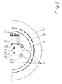
- FIG. 1 shows a side view of the wheel hub drive according to FIG. 1 from the right, in this case of the. the side of the wheel hub drive facing the center of the vehicle.
- the bore 42 or the like For receiving the Connection line 41 for guiding the cooling medium in the support plate pin open at the Outside of the support plate 6. In this case, two bores 42 are parallel to each other arranged. Below the bore 42 or the like.
- a feed line 18 is for the Feeding of oil, glycerin or the like into the pressing grooves can be seen.
- a terminal box 12 with the electrical connections 11 of the wheel hub drive arranged.
- the terminal box 12 is fastened to the support plate 6 by screws 12a or the like.
- FIG. 3 schematically shows the connection of the wheel hub drive to the car body 23 of a rail vehicle.
- Two wheel hub drives are mutually perpendicular to the direction of travel arranged opposite each other.
- the with the rotor housing 8 of the wheel hub drives connected wheel tires 1 run on rails 28.
- the carrying plates 6 of the invention opposite wheel hub drives are over the vehicle frame 19, such as a Axle bridge, interconnected, which the car body 23, preferably via springs 29, e.g. Primary springs.
- FIG. 4 shows a variant of the wheel hub drive according to the invention for the tire 4 not rail-bound vehicle.
- Such drives find e.g. for trolleybuses, trolleybuses or so-called people movers at airports.
- it is Rotor housing 8 by means of an intermediate ring 31 and screws 32 or the like with the rim 5, which carries the tire 4, firmly connected.
- the rim is 5 for an easy tire change removable after removing the screws 32.
Landscapes
- Engineering & Computer Science (AREA)
- Transportation (AREA)
- Mechanical Engineering (AREA)
- Power Engineering (AREA)
- Chemical & Material Sciences (AREA)
- Combustion & Propulsion (AREA)
- Electromagnetism (AREA)
- Sustainable Energy (AREA)
- Sustainable Development (AREA)
- Physics & Mathematics (AREA)
- Life Sciences & Earth Sciences (AREA)
- Arrangement Or Mounting Of Propulsion Units For Vehicles (AREA)
- Arrangement And Mounting Of Devices That Control Transmission Of Motive Force (AREA)
- Braking Arrangements (AREA)
- Lubricants (AREA)
- Transmissions By Endless Flexible Members (AREA)
- Automatic Cycles, And Cycles In General (AREA)
- Motor Power Transmission Devices (AREA)
- Connection Of Motors, Electrical Generators, Mechanical Devices, And The Like (AREA)
Abstract
Description
- Fig. 1
- einen Längsschnitt eines Radnabenantriebs für den Radreifen eines Schienenfahrzeuges,
- Fig. 1a
- das Detail A der Fig. 1 in größerem Maßstab,
- Fig. 1b
- das Detail B der Fig. 1 in größerem Maßstab;
- Fig. 2
- eine Seitenansicht des Radnabenantriebs gemäß Fig. 1,
- Fig. 3
- schematisch die Verbindung des erfindungsgemäßen Radnabenantriebs mit dem Wagenkasten eines Schienenfahrzeuges, und
- Fig. 4
- eine Variante des Radnabenantriebs für das Rad eines nicht schienengebundenen Fahrzeuges.
Claims (10)
- Elektromotorischer Radnabenantrieb für ein Fahrzeugrad, insbesondere für ein Rad eines Schienenfahrzeuges, unter Verwendung eines Außenläufermotors, bei dem das Rotorgehäuse mit dem Fahrzeugrad verbunden ist und der Stator auf einer stillstehenden Achse sitzt, welche Achse einseitig am Fahrzeugrahmen od. dgl. aufgehängt ist, dadurch gekennzeichnet, daß die einseitige Aufhängung über ein mit der Achse (14) verbundenes Tragschild (6) geschieht, welches Tragschild (6) einen Tragschildzapfen (7) aufweist, der in eine Bohrung (15) in der Achse (14) in das Innere des Radnabenantriebs hineinragt.
- Radnabenantrieb nach Anspruch 1, dadurch gekennzeichnet, daß das Tragschild (6) an der, der Fahrzeugmitte zugewandten Seite des Radnabenantriebs mit der Achse (14) verbunden ist.
- Radnabenantrieb nach Anspruch 1 oder 2, dadurch gekennzeichnet, daß der Tragschildzapfen (7) bis über den mittleren Aufstandspunkt (24) des Fahrzeugrades (1, 4) in das Innere des Radnabenantriebs hineinragt.
- Radnabenantrieb nach einem der Ansprüche 1 bis 3, dadurch gekennzeichnet, daß die Bohrung (15) in der Achse (14) in Richtung des Inneren des Radnabenantriebs konisch verjüngend ausgebildet ist, und daß der Tragschildzapfen (7) zur Bohrung (15) vorzugsweise komplementäre Gestalt aufweist.
- Radnabenantrieb nach mindestens einem der Ansprüche 1 bis 4, dadurch gekennzeichnet, daß der Tragschildzapfen (7) mindestens eine, vorzugsweise ringförmige Abpreßnut (17) aufweist, welche mit mindestens einer Zuleitung (18) verbunden ist.
- Radnabenantrieb nach mindestens einem der Ansprüche 1 bis 5, dadurch gekennzeichnet, daß die Achse (14) mäanderförmig verlaufende Kühlkanäle (9) aufweist, deren Anschlüsse (10) an der Stirnseite der Bohrung (15) in der Achse (12) münden.
- Radnabenantrieb nach mindestens einem der Ansprüche 1 bis 5, dadurch gekennzeichnet, daß die Achse (14) Kühlkanäle (9) in Form einer Doppelschraube bzw. -spirale aufweist, deren Anschlüsse (10) an der Stirnseite der Bohrung (15) in der Achse (12) münden.
- Radnabenantrieb nach Anspruch 6 oder 7, dadurch gekennzeichnet, daß im Tragschildzapfen (7) Bohrungen (42) od. dgl. zur Aufnahme von Anschlußleitungen zur Führung des Kühlmediums enthalten sind.
- Radnabenantrieb nach mindestens einem der Ansprüche 1 bis 8, dadurch gekennzeichnet, daß elektrische Anschlüsse (11) des Radnabenantriebs in einem am Tragschild (6) befestigten Klemmenkasten (12) angeordnet sind.
- Radnabenantrieb nach mindestens einem der Ansprüche 1 bis 9, dadurch gekennzeichnet, daß der Radnabenantrieb durch eine Synchron-, Asynchron- oder Transversalflußmaschine gebildet ist.
Applications Claiming Priority (3)
| Application Number | Priority Date | Filing Date | Title |
|---|---|---|---|
| AT48497 | 1997-03-19 | ||
| AT484/97 | 1997-03-19 | ||
| AT0048497A AT405390B (de) | 1997-03-19 | 1997-03-19 | Elektromotorischer radnabenantrieb für ein fahrzeugrad |
Publications (2)
| Publication Number | Publication Date |
|---|---|
| EP0865978A1 true EP0865978A1 (de) | 1998-09-23 |
| EP0865978B1 EP0865978B1 (de) | 1999-06-30 |
Family
ID=3491829
Family Applications (1)
| Application Number | Title | Priority Date | Filing Date |
|---|---|---|---|
| EP98890058A Expired - Lifetime EP0865978B1 (de) | 1997-03-19 | 1998-03-05 | Elektromotorischer Radnabenantrieb für ein Fahrzeugrad |
Country Status (8)
| Country | Link |
|---|---|
| EP (1) | EP0865978B1 (de) |
| JP (1) | JPH10271754A (de) |
| AT (2) | AT405390B (de) |
| AU (1) | AU724568B2 (de) |
| CZ (1) | CZ284477B6 (de) |
| DE (1) | DE59800010D1 (de) |
| ES (1) | ES2135985T3 (de) |
| PL (1) | PL185739B1 (de) |
Cited By (8)
| Publication number | Priority date | Publication date | Assignee | Title |
|---|---|---|---|---|
| EP0937585A3 (de) * | 1998-02-19 | 2001-05-09 | Gabbidon, Willitz Decartered | Radvorrichtung |
| EP1223068A1 (de) * | 2001-01-11 | 2002-07-17 | Lothar Bieschewski | Antriebsrad eines Elektrofahrzeugs |
| EP1258410A1 (de) * | 2001-05-08 | 2002-11-20 | Gutehoffnungshütte Radsatz GmbH | Losrad-Anordnung für Schienenfahrzeuge |
| EP1568530A3 (de) * | 2000-01-26 | 2006-10-04 | e-Traction Europe B.V. | Rad mit Antriebsmitteln |
| WO2013001480A2 (en) | 2011-06-28 | 2013-01-03 | Gyoeker Gyula Istvan | Railway vehicle wheel with in-wheel motor |
| US9233603B2 (en) | 2000-01-26 | 2016-01-12 | E-Traction Europe B.V. | Wheel provided with driving means |
| WO2018024295A1 (de) * | 2016-08-02 | 2018-02-08 | Ziehl-Abegg Automotive Gmbh & Co. Kg | Radnabenantrieb |
| CN108016287A (zh) * | 2017-09-20 | 2018-05-11 | 北京理工大学 | 低地板模块化电动车桥 |
Families Citing this family (8)
| Publication number | Priority date | Publication date | Assignee | Title |
|---|---|---|---|---|
| JP2012508549A (ja) | 2008-11-03 | 2012-04-05 | モーター エクセレンス, エルエルシー | 横方向および/またはコンミュテート式磁束システムの固定子の概念 |
| WO2011115633A1 (en) | 2010-03-15 | 2011-09-22 | Motor Excellence Llc | Transverse and/or commutated flux system for electric bicycles |
| CN102959832B (zh) | 2010-03-15 | 2016-11-16 | 电扭矩机器股份有限公司 | 具有相偏移的横向和/或换向通量系统 |
| WO2011115632A1 (en) | 2010-03-15 | 2011-09-22 | Motor Excellence Llc | Transverse and/or commutated flux systems configured to provide reduced flux leakage, hysteresis loss reduction, and phase matching |
| EP2551995B1 (de) * | 2010-03-26 | 2017-03-01 | Honda Motor Co., Ltd. | Fahrzeug mit antriebsmotor |
| DE102010016770B4 (de) | 2010-05-04 | 2013-01-17 | Martin Locher | Fahrzeug |
| RU2709055C1 (ru) * | 2019-02-11 | 2019-12-13 | Акционерное общество Научно-исследовательский и конструкторско-технологический институт подвижного состава (АО "ВНИКТИ") | Колёсно-моторный блок |
| CN111547080B (zh) * | 2020-05-15 | 2021-11-16 | 中车株洲电力机车有限公司 | 一种开关磁阻电机直驱的独立轮对及单轴转向架 |
Citations (4)
| Publication number | Priority date | Publication date | Assignee | Title |
|---|---|---|---|---|
| EP0413337A1 (de) | 1989-08-18 | 1991-02-20 | Magnet-Motor Gesellschaft Für Magnetmotorische Technik Mbh | Elektromotorischer Schienenfahrzeug-Direktantrieb |
| EP0579084A1 (de) | 1992-07-17 | 1994-01-19 | Siemens Aktiengesellschaft | Antriebsmotor |
| EP0582563A1 (de) * | 1992-08-05 | 1994-02-09 | ABB VERKEHRSTECHNIK Gesellschaft m.b.h. | Schienenfahrzeug-Direktantrieb für ein Fahrzeugrad |
| DE4230137A1 (de) * | 1992-09-09 | 1994-03-10 | Abb Henschel Waggon Union | Einzelrad mit Radnabenmotor für Schienenfahrzeuge |
Family Cites Families (4)
| Publication number | Priority date | Publication date | Assignee | Title |
|---|---|---|---|---|
| FR2379394A1 (fr) * | 1977-02-04 | 1978-09-01 | Poclain Hydraulics Sa | Dispositif de fixation et d'entrainement d'un organe de deplacement d'un vehicule |
| JP2554697B2 (ja) * | 1988-03-29 | 1996-11-13 | 新日本製鐵株式会社 | 電気自動車のモータ冷却装置 |
| IT1244276B (it) * | 1990-07-03 | 1994-07-08 | Elettromeccanica Parizzi Spa | Gruppo ruota-motore elettrico per carrelli di veicoli ferrotranviari |
| IT1241366B (it) * | 1990-12-21 | 1994-01-10 | Fiat Auto Spa | Gruppo ruota-motore per un veicolo a trazione elettrica |
-
1997
- 1997-03-19 AT AT0048497A patent/AT405390B/de not_active IP Right Cessation
-
1998
- 1998-03-05 EP EP98890058A patent/EP0865978B1/de not_active Expired - Lifetime
- 1998-03-05 AT AT98890058T patent/ATE181706T1/de active
- 1998-03-05 AU AU57391/98A patent/AU724568B2/en not_active Ceased
- 1998-03-05 DE DE59800010T patent/DE59800010D1/de not_active Expired - Lifetime
- 1998-03-05 ES ES98890058T patent/ES2135985T3/es not_active Expired - Lifetime
- 1998-03-09 CZ CZ98692A patent/CZ284477B6/cs not_active IP Right Cessation
- 1998-03-10 PL PL98325226A patent/PL185739B1/pl not_active IP Right Cessation
- 1998-03-18 JP JP10068376A patent/JPH10271754A/ja active Pending
Patent Citations (5)
| Publication number | Priority date | Publication date | Assignee | Title |
|---|---|---|---|---|
| EP0413337A1 (de) | 1989-08-18 | 1991-02-20 | Magnet-Motor Gesellschaft Für Magnetmotorische Technik Mbh | Elektromotorischer Schienenfahrzeug-Direktantrieb |
| EP0579084A1 (de) | 1992-07-17 | 1994-01-19 | Siemens Aktiengesellschaft | Antriebsmotor |
| EP0582563A1 (de) * | 1992-08-05 | 1994-02-09 | ABB VERKEHRSTECHNIK Gesellschaft m.b.h. | Schienenfahrzeug-Direktantrieb für ein Fahrzeugrad |
| AT401761B (de) | 1992-08-05 | 1996-11-25 | Abb Daimler Benz Transp | Getriebeloser radnabenmotor für ein rad eines schienenfahrzeuges |
| DE4230137A1 (de) * | 1992-09-09 | 1994-03-10 | Abb Henschel Waggon Union | Einzelrad mit Radnabenmotor für Schienenfahrzeuge |
Cited By (13)
| Publication number | Priority date | Publication date | Assignee | Title |
|---|---|---|---|---|
| EP0937585A3 (de) * | 1998-02-19 | 2001-05-09 | Gabbidon, Willitz Decartered | Radvorrichtung |
| US9233603B2 (en) | 2000-01-26 | 2016-01-12 | E-Traction Europe B.V. | Wheel provided with driving means |
| EP1568530A3 (de) * | 2000-01-26 | 2006-10-04 | e-Traction Europe B.V. | Rad mit Antriebsmitteln |
| EP2284031A3 (de) * | 2000-01-26 | 2011-04-27 | e-Traction Europe B.V. | Rad mit Antriebsmitteln |
| EP1223068A1 (de) * | 2001-01-11 | 2002-07-17 | Lothar Bieschewski | Antriebsrad eines Elektrofahrzeugs |
| EP1258410A1 (de) * | 2001-05-08 | 2002-11-20 | Gutehoffnungshütte Radsatz GmbH | Losrad-Anordnung für Schienenfahrzeuge |
| KR100822091B1 (ko) * | 2001-05-08 | 2008-04-15 | 구테호프눙쉬테 라드사츠 게엠베하 | 궤도 차량용 아이들러 휠 장치 |
| WO2013001480A2 (en) | 2011-06-28 | 2013-01-03 | Gyoeker Gyula Istvan | Railway vehicle wheel with in-wheel motor |
| WO2018024295A1 (de) * | 2016-08-02 | 2018-02-08 | Ziehl-Abegg Automotive Gmbh & Co. Kg | Radnabenantrieb |
| CN109562684A (zh) * | 2016-08-02 | 2019-04-02 | 施乐百有限公司 | 轮毂驱动装置 |
| US11220174B2 (en) | 2016-08-02 | 2022-01-11 | Ziehl-Abegg Automotive Gmbh & Co. Kg | Wheel hub drive |
| CN108016287A (zh) * | 2017-09-20 | 2018-05-11 | 北京理工大学 | 低地板模块化电动车桥 |
| CN108016287B (zh) * | 2017-09-20 | 2023-08-18 | 北京理工大学 | 低地板模块化电动车桥 |
Also Published As
| Publication number | Publication date |
|---|---|
| CZ69298A3 (cs) | 1998-12-16 |
| DE59800010D1 (de) | 1999-08-05 |
| PL185739B1 (pl) | 2003-07-31 |
| JPH10271754A (ja) | 1998-10-09 |
| ES2135985T3 (es) | 1999-11-01 |
| ATA48497A (de) | 1998-12-15 |
| AT405390B (de) | 1999-07-26 |
| AU724568B2 (en) | 2000-09-28 |
| ATE181706T1 (de) | 1999-07-15 |
| PL325226A1 (en) | 1998-09-28 |
| AU5739198A (en) | 1998-09-24 |
| EP0865978B1 (de) | 1999-06-30 |
| CZ284477B6 (cs) | 1998-12-16 |
Similar Documents
| Publication | Publication Date | Title |
|---|---|---|
| EP0865978B1 (de) | Elektromotorischer Radnabenantrieb für ein Fahrzeugrad | |
| DE112009003757B4 (de) | Radantriebsvorrichtung | |
| DE69911275T2 (de) | Flugzeugbremse mit elektromechanischen Betätigungsmodulen sowie Methode zu deren Wartung | |
| DE19506888C2 (de) | Antriebseinheit für elektrische Schienenfahrzeuge | |
| DE2501134A1 (de) | Schnellaufendes fahrgestell mit elastischen raedern | |
| AT408333B (de) | Fahrzeugrad | |
| DE19954585A1 (de) | Verfahren zum Herstellen eines Reibringes, insbesondere für eine Bremsscheibe und Bremsscheibe | |
| AT401761B (de) | Getriebeloser radnabenmotor für ein rad eines schienenfahrzeuges | |
| DE3730983A1 (de) | Scheibenbremsmotor | |
| DE112021000773B4 (de) | Elektrofahrzeug und verfahren zur herstellung desselben | |
| DE2606807B2 (de) | Elektromotor zum beidseitigen Abtrieb | |
| EP0052244B1 (de) | Drehgestell für Schienenfahrzeuge, wie Strassenbahnen | |
| EP0542173A1 (de) | Antriebseinheit für Schienentriebfahrzeuge | |
| DE4316201C2 (de) | Laufradblock | |
| EP3980312B1 (de) | Einzelachsantrieb und schienenfahrzeug | |
| EP1065122B1 (de) | Losradachse für Schienenfahrzeuge | |
| DE202011103889U1 (de) | Einrichtung an Portaldrehmaschinen zum Bearbeiten von Eisenbahnradsätzen mit Achslagergehäusen | |
| EP0855989B1 (de) | Laufradblock | |
| EP3319754A1 (de) | Antriebsanordnung für eine schwenkbrücke | |
| EP0814993A1 (de) | Elektrofahrzeug, insbesondere elektrisch angetriebenes schienenfahrzeug, zum beispiel niederflurstrassenbahn | |
| DE19540217C1 (de) | Laufradblock mit einem Gehäuse | |
| DE3931912A1 (de) | Einzelradlagerung eines triebrades an schienenfahrzeugen | |
| DE4429173C1 (de) | Antriebsaggregat | |
| EP0727528B1 (de) | Kehrvorrichtung für Arbeitsfahrzeuge | |
| EP0638980A1 (de) | Antriebsaggregat |
Legal Events
| Date | Code | Title | Description |
|---|---|---|---|
| PUAI | Public reference made under article 153(3) epc to a published international application that has entered the european phase |
Free format text: ORIGINAL CODE: 0009012 |
|
| AK | Designated contracting states |
Kind code of ref document: A1 Designated state(s): AT BE CH DE ES FR GB IT LI NL SE |
|
| AX | Request for extension of the european patent |
Free format text: AL;LT;LV;MK;RO;SI |
|
| GRAG | Despatch of communication of intention to grant |
Free format text: ORIGINAL CODE: EPIDOS AGRA |
|
| 17P | Request for examination filed |
Effective date: 19980929 |
|
| 17Q | First examination report despatched |
Effective date: 19981123 |
|
| GRAG | Despatch of communication of intention to grant |
Free format text: ORIGINAL CODE: EPIDOS AGRA |
|
| GRAH | Despatch of communication of intention to grant a patent |
Free format text: ORIGINAL CODE: EPIDOS IGRA |
|
| GRAA | (expected) grant |
Free format text: ORIGINAL CODE: 0009210 |
|
| AKX | Designation fees paid |
Free format text: AT BE CH DE ES FR GB IT LI NL SE |
|
| RBV | Designated contracting states (corrected) |
Designated state(s): AT BE CH DE ES FR GB IT LI NL SE |
|
| AK | Designated contracting states |
Kind code of ref document: B1 Designated state(s): AT BE CH DE ES FR GB IT LI NL SE |
|
| REF | Corresponds to: |
Ref document number: 181706 Country of ref document: AT Date of ref document: 19990715 Kind code of ref document: T |
|
| REG | Reference to a national code |
Ref country code: CH Ref legal event code: NV Representative=s name: FREI PATENTANWALTSBUERO Ref country code: CH Ref legal event code: EP |
|
| GBT | Gb: translation of ep patent filed (gb section 77(6)(a)/1977) |
Effective date: 19990630 |
|
| ET | Fr: translation filed | ||
| REF | Corresponds to: |
Ref document number: 59800010 Country of ref document: DE Date of ref document: 19990805 |
|
| ITF | It: translation for a ep patent filed | ||
| REG | Reference to a national code |
Ref country code: ES Ref legal event code: FG2A Ref document number: 2135985 Country of ref document: ES Kind code of ref document: T3 |
|
| PLBE | No opposition filed within time limit |
Free format text: ORIGINAL CODE: 0009261 |
|
| STAA | Information on the status of an ep patent application or granted ep patent |
Free format text: STATUS: NO OPPOSITION FILED WITHIN TIME LIMIT |
|
| 26N | No opposition filed | ||
| REG | Reference to a national code |
Ref country code: GB Ref legal event code: IF02 |
|
| NLS | Nl: assignments of ep-patents |
Owner name: BOMBARDIER TRANSPORTATION GMBH |
|
| NLT1 | Nl: modifications of names registered in virtue of documents presented to the patent office pursuant to art. 16 a, paragraph 1 |
Owner name: BOMBARDIER TRANSPORTATION AUSTRIA GMBH |
|
| REG | Reference to a national code |
Ref country code: CH Ref legal event code: PUE Owner name: BOMBARDIER TRANSPORTATION AUSTRIA GMBH TRANSFER- B Ref country code: CH Ref legal event code: PFA Free format text: ABB DAIMLER BENZ TRANSPORTATION AUSTRIA GMBH TRANSFER- BOMBARDIER TRANSPORTATION AUSTRIA GMBH |
|
| REG | Reference to a national code |
Ref country code: ES Ref legal event code: PC2A |
|
| BECH | Be: change of holder |
Free format text: 20020215 *BOMBARDIER TRANSPORTATION G.M.B.H. |
|
| PGFP | Annual fee paid to national office [announced via postgrant information from national office to epo] |
Ref country code: SE Payment date: 20030318 Year of fee payment: 6 |
|
| PG25 | Lapsed in a contracting state [announced via postgrant information from national office to epo] |
Ref country code: SE Free format text: LAPSE BECAUSE OF NON-PAYMENT OF DUE FEES Effective date: 20040306 |
|
| REG | Reference to a national code |
Ref country code: GB Ref legal event code: 732E |
|
| EUG | Se: european patent has lapsed | ||
| REG | Reference to a national code |
Ref country code: FR Ref legal event code: PLFP Year of fee payment: 18 |
|
| PGFP | Annual fee paid to national office [announced via postgrant information from national office to epo] |
Ref country code: NL Payment date: 20150319 Year of fee payment: 18 Ref country code: CH Payment date: 20150319 Year of fee payment: 18 Ref country code: IT Payment date: 20150326 Year of fee payment: 18 Ref country code: ES Payment date: 20150326 Year of fee payment: 18 Ref country code: DE Payment date: 20150320 Year of fee payment: 18 |
|
| PGFP | Annual fee paid to national office [announced via postgrant information from national office to epo] |
Ref country code: GB Payment date: 20150319 Year of fee payment: 18 Ref country code: AT Payment date: 20150320 Year of fee payment: 18 Ref country code: FR Payment date: 20150319 Year of fee payment: 18 |
|
| PGFP | Annual fee paid to national office [announced via postgrant information from national office to epo] |
Ref country code: BE Payment date: 20150319 Year of fee payment: 18 |
|
| PG25 | Lapsed in a contracting state [announced via postgrant information from national office to epo] |
Ref country code: BE Free format text: LAPSE BECAUSE OF NON-PAYMENT OF DUE FEES Effective date: 20160331 |
|
| REG | Reference to a national code |
Ref country code: DE Ref legal event code: R119 Ref document number: 59800010 Country of ref document: DE |
|
| REG | Reference to a national code |
Ref country code: CH Ref legal event code: PL |
|
| REG | Reference to a national code |
Ref country code: AT Ref legal event code: MM01 Ref document number: 181706 Country of ref document: AT Kind code of ref document: T Effective date: 20160305 |
|
| REG | Reference to a national code |
Ref country code: NL Ref legal event code: MM Effective date: 20160401 |
|
| GBPC | Gb: european patent ceased through non-payment of renewal fee |
Effective date: 20160305 |
|
| REG | Reference to a national code |
Ref country code: FR Ref legal event code: ST Effective date: 20161130 |
|
| PG25 | Lapsed in a contracting state [announced via postgrant information from national office to epo] |
Ref country code: GB Free format text: LAPSE BECAUSE OF NON-PAYMENT OF DUE FEES Effective date: 20160305 Ref country code: CH Free format text: LAPSE BECAUSE OF NON-PAYMENT OF DUE FEES Effective date: 20160331 Ref country code: DE Free format text: LAPSE BECAUSE OF NON-PAYMENT OF DUE FEES Effective date: 20161001 Ref country code: FR Free format text: LAPSE BECAUSE OF NON-PAYMENT OF DUE FEES Effective date: 20160331 Ref country code: LI Free format text: LAPSE BECAUSE OF NON-PAYMENT OF DUE FEES Effective date: 20160331 Ref country code: NL Free format text: LAPSE BECAUSE OF NON-PAYMENT OF DUE FEES Effective date: 20160401 |
|
| PG25 | Lapsed in a contracting state [announced via postgrant information from national office to epo] |
Ref country code: IT Free format text: LAPSE BECAUSE OF NON-PAYMENT OF DUE FEES Effective date: 20160305 Ref country code: AT Free format text: LAPSE BECAUSE OF NON-PAYMENT OF DUE FEES Effective date: 20160305 |
|
| REG | Reference to a national code |
Ref country code: ES Ref legal event code: FD2A Effective date: 20170428 |
|
| PG25 | Lapsed in a contracting state [announced via postgrant information from national office to epo] |
Ref country code: ES Free format text: LAPSE BECAUSE OF NON-PAYMENT OF DUE FEES Effective date: 20160306 |