EP0865988A1 - Vorrichtung zum Stapeln von zu verpackenden sortierten Gegenständen - Google Patents
Vorrichtung zum Stapeln von zu verpackenden sortierten Gegenständen Download PDFInfo
- Publication number
- EP0865988A1 EP0865988A1 EP98830125A EP98830125A EP0865988A1 EP 0865988 A1 EP0865988 A1 EP 0865988A1 EP 98830125 A EP98830125 A EP 98830125A EP 98830125 A EP98830125 A EP 98830125A EP 0865988 A1 EP0865988 A1 EP 0865988A1
- Authority
- EP
- European Patent Office
- Prior art keywords
- belt
- cans
- group
- groups
- speed
- Prior art date
- Legal status (The legal status is an assumption and is not a legal conclusion. Google has not performed a legal analysis and makes no representation as to the accuracy of the status listed.)
- Withdrawn
Links
- 238000011144 upstream manufacturing Methods 0.000 claims description 7
- 239000002985 plastic film Substances 0.000 claims description 5
- 229920006255 plastic film Polymers 0.000 claims description 5
- 230000003019 stabilising effect Effects 0.000 claims description 3
- 230000003213 activating effect Effects 0.000 claims description 2
- 230000006641 stabilisation Effects 0.000 claims description 2
- 238000000034 method Methods 0.000 claims 4
- 238000004806 packaging method and process Methods 0.000 description 3
- 238000004519 manufacturing process Methods 0.000 description 2
- 238000010276 construction Methods 0.000 description 1
- 238000012986 modification Methods 0.000 description 1
- 230000004048 modification Effects 0.000 description 1
Images


Classifications
-
- B—PERFORMING OPERATIONS; TRANSPORTING
- B65—CONVEYING; PACKING; STORING; HANDLING THIN OR FILAMENTARY MATERIAL
- B65G—TRANSPORT OR STORAGE DEVICES, e.g. CONVEYORS FOR LOADING OR TIPPING, SHOP CONVEYOR SYSTEMS OR PNEUMATIC TUBE CONVEYORS
- B65G57/00—Stacking of articles
- B65G57/32—Stacking of articles characterised by stacking during transit
-
- B—PERFORMING OPERATIONS; TRANSPORTING
- B65—CONVEYING; PACKING; STORING; HANDLING THIN OR FILAMENTARY MATERIAL
- B65B—MACHINES, APPARATUS OR DEVICES FOR, OR METHODS OF, PACKAGING ARTICLES OR MATERIALS; UNPACKING
- B65B35/00—Supplying, feeding, arranging or orientating articles to be packaged
- B65B35/30—Arranging and feeding articles in groups
- B65B35/50—Stacking one article, or group of articles, upon another before packaging
Definitions
- the present invention relates to a device for the stacking of continuously fed groups of sorted articles. It is particularly applicable on machines for packaging groups of products in boxes using shrink-wrap plastic film.
- the production line (which has the task of defining and sorting a group of products to then package them according to different criteria) is made up in the following way: a station which continuously feeds products, such as cans or similar of various shapes and sizes, placed upstream of the machine relative to the direction in which the cans are moving.
- the latter move forward continuously in ordered rows one behind the other on a horizontally moving conveyor belt towards an intermediate sorting station designed to select the format of the groups of cans to be wrapped (that is to say the number).
- This intermediate station has a second horizontally moving conveyor belt at the end of which there is a station that feeds cardboard sheets which are used to make the base for each group of cans. The cardboard sheets are fed from a position below the machine.
- the aim of the present invention is to create a device for stacking groups of sorted products to be packaged. It is designed in such away as to permit its use in conjunction with existing machinery by making small adjustments to said machinery without altering its ease of use, safety aspects and speed of production.
- the stacking device in question is applicable on all automatic machines for the wrapping of groups of products, which here have been shown as cans 2 purely by way of example, but it is obvious that any other type of product that can be stacked into at least two groups of the same product could make use of such a device without affecting the scope of the inventive concept.
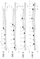
- the machine illustrated in figure 1 is made up of a group of stations (labelled 3) placed one after the other in a feed direction A and equipped with sorting means 4.
- the latter acts on said cans 2 to create groups 1 whose length can be predetermined, each group 1 being equipped with a sheet 5 to act as a base. Furthermore each group 1 is spaced from the previous and successive one according to a pre-set gap L, relative to feed direction A.
- this first group of stations 3 is made up of a first horizontal sorting belt 8 closed in a loop around a first set of motorised pulleys 31 and is equipped, at its downstream end, relative to feed direction A, with the above mentioned sorting means 4 (here illustrated schematically in that they do not strictly form part of the invention).
- sorting means 4 act on cans 2 so that groups 1 of cans 2 can be passed one after the other from the first feed belt 30 to a second feed belt 32, which is closed in a loop around a second set of motorised pulleys 33, equipped with a set of crosspieces 32t for pushing the groups 1.
- a station 34, for feeding the above mentioned sheets 5, is located near the downstream end, relative to the feed direction A, of the second conveyor belt 32.
- the sheets 5 are fed from a line that is positioned below the line along which the groups 1 of cans 2 are fed so that the sheets 5 can be placed underneath said cans at an intermediate conveyor station 8 for the groups 1.
- This intermediate station 8 constitutes part of a stacking station 7 made up of two other belts 8 and 10 (better described below).
- the intermediate station 8 is positioned between the above mentioned feed belt 32 and a station 6 for wrapping the groups 1 of cans 2 in a sheet of plastic film. (This station 6 is only partially illustrated in that it does not strictly form part of the invention).
- FIG 1 shows that the first belt 8 is equipped with first drive means 9 to move the downstream end 8a of the first belt 8, relative to the feed direction A, from a horizontal to a raised position, that is to say inclined position in order to alternately feed a single group of cans onto a second and third belt 10 and 11.
- first drive means 9 consist of a piston 16 positioned underneath the first belt 8.
- the free end of the piston's stem 17 is connected to the first belt 8 in order to obtain the above mentioned horizontal and inclined positions.
- the upstream end 8b, relative to the feed direction A, of the first belt 8 is pivoted at B to a load-bearing structure 20 attached to the machine.
- the second belt 10 extends horizontally between the first belt 8 and the above mentioned wrapping station 6 and moves at a constant speed V10 that is equal to the speed V8 of the first belt 8.
- This second belt 10 extends in such a way that its downstream end is connected to the above mentioned wrapping station 6.
- the above mentioned third belt 11 is positioned above the second belt 10 at a height H that can be altered according to the height of the cans 2 in order to create a passage-way for the lower set of cans 1' which have been fed from the first belt 8.
- the active conveying branch 11r of the third belt 11 is concave in profile in that its outline is defined by a support structure which divides the active conveying branch 11r into three uninterrupted portions: the first, infeed portion 11a is placed upstream relative to feed direction A and is inclined upwards; the second, intermediate portion 11b extends in a straight line parallel to the second belt 10, while the third, outfeed portion 11c, located downstream of the previous portion, is inclined downwards.
- the third belt 11 is connected to a second drive means 12 designed to move the third belt at a variable speed V11 so as to permit the loading of an upper group 1" of cans in arrival from the first belt 8 and the simultaneous unloading of the previous upper group of cans 1" onto a group of lower cans 1', that are constantly moving forward on the second belt 10, at the downstream end of the second belt.
- These second drive means 12 consist of a variable timing drive (as, for example, a conventional brushless motor.) connected, via a second return pulley 12p, to a first pulley 13a for driving the third belt 11 forming part of a plurality of pulleys 13 around which the third belt 11 is looped.
- a variable timing drive as, for example, a conventional brushless motor.
- Figure 2 shows the means 18 for adjusting the height H of the third belt 11 relative to the second belt 10.
- These means are made up of a plurality of vertical arms 19 which are placed on either side of the third belt 11 and joined to the above mentioned fixed load bearing structure 20 of the machine.
- These arms 19 support threaded rods 21, that can be rotated on their axes and screwed to their respective threaded bushes 22 which are attached to the sides 14a of the load support structure 14 of the third belt 11.
- means 23 for activating the rotation of the rods 21 are envisaged. These might consist of a mechanism made up of a toothed wheel 27, joined to the upper end of each of the two rods 21, onto which is engaged a chain 28 that is closed in a loop around said rods.
- One of the rods 21 is equipped with a crank 26 that is connected to its toothed wheel 27.
- the rotation of this crank resulting in the movement of the chain 28, allows the whole of the third belt 11 to be raised or lowered (see arrow F in figure 2).
- This adjusting movement is transmitted to second drive means 12 which are rigidly connected to the third belt 11 and are supported by guides 29.
- crank 26 can be substituted by an automatic drive system connected to the machine's central control unit.
- an automatic drive system connected to the machine's central control unit.
- Such a system might envisage, for example, the use of an encoder to check the position of the third belt 11.
- the numeral 24 indicates the means for stabilising the upper groups 1" of cans 2 with which the third belt can be equipped.
- these stabilisation means have been shown as a fourth belt 25 (shown as a dashed line), positioned above the first portion 11a of the active branch 11r, whose lower active branch 25r is parallel to the first portion: this prevents the cans 2 from moving slightly out of position on the upwards incline of the portion 11a.
- Such a device therefore, achieves the stated aims thanks to an extremely simple stacking structure with low application costs and without necessarily having to alter either the general make-up of the wrapping machine or the positioning of the existing stations of conventional machines.
- the simplicity of construction and above all the use of a variable timing drive ensure that the rate of productive output over time is maintained.
Landscapes
- Engineering & Computer Science (AREA)
- Mechanical Engineering (AREA)
- Container Filling Or Packaging Operations (AREA)
Applications Claiming Priority (2)
| Application Number | Priority Date | Filing Date | Title |
|---|---|---|---|
| ITBO970139 | 1997-03-12 | ||
| IT97BO000139A IT1291255B1 (it) | 1997-03-12 | 1997-03-12 | Dispositivo per l'impilamento di gruppi di prodotti selezionati da impacchettare. |
Publications (1)
| Publication Number | Publication Date |
|---|---|
| EP0865988A1 true EP0865988A1 (de) | 1998-09-23 |
Family
ID=11342087
Family Applications (1)
| Application Number | Title | Priority Date | Filing Date |
|---|---|---|---|
| EP98830125A Withdrawn EP0865988A1 (de) | 1997-03-12 | 1998-03-09 | Vorrichtung zum Stapeln von zu verpackenden sortierten Gegenständen |
Country Status (2)
| Country | Link |
|---|---|
| EP (1) | EP0865988A1 (de) |
| IT (1) | IT1291255B1 (de) |
Cited By (9)
| Publication number | Priority date | Publication date | Assignee | Title |
|---|---|---|---|---|
| WO2004052726A1 (en) * | 2002-12-11 | 2004-06-24 | Meadwestvaco Packaging Systems Llc | Article aligning apparatus |
| US7156606B2 (en) | 2002-12-11 | 2007-01-02 | Meadwestvaco Packaging Systems, Llc | Article aligning apparatus |
| DE102006058370A1 (de) * | 2006-12-08 | 2008-06-12 | Focke & Co.(Gmbh & Co. Kg) | Verfahren und Vorrichtung zum Herstellen von Zigarettenpackungen |
| WO2008074327A1 (en) * | 2006-12-20 | 2008-06-26 | Schur Packaging Systems A/S | Wrapper |
| GB2447763A (en) * | 2008-03-18 | 2008-09-24 | Gd Spa | Group forming system |
| DE102013113199A1 (de) * | 2013-11-28 | 2015-05-28 | Textor Maschinenbau GmbH | Vorrichtung und Verfahren zum Erstellen von Formatsätzen aus Kombinationsportionen |
| CN105314405A (zh) * | 2015-12-05 | 2016-02-10 | 重庆元创自动化设备有限公司 | 一种防止工件叠放位置颠倒的传送装置 |
| EP3162740A1 (de) | 2015-10-29 | 2017-05-03 | C.E.R.M.E.X. Constructions Etudes Et Recherches De Materiels Pour L'emballage D'expedition | Überlagerungsvorrichtung und -methode |
| DE102016121576A1 (de) * | 2016-11-10 | 2018-05-17 | Meurer Verpackungssysteme Gmbh | Verfahren und Vorrichtung zum Stapeln von Produkten |
Citations (5)
| Publication number | Priority date | Publication date | Assignee | Title |
|---|---|---|---|---|
| DE2558340A1 (de) * | 1975-12-23 | 1977-07-07 | Dunlopillo Gmbh | Verfahren und vorrichtung zur stapelung von blockfoermigen guetern |
| US4450949A (en) * | 1982-12-06 | 1984-05-29 | Five X Corporation | Machine for transporting and stacking loaded cartons |
| GB2163119A (en) * | 1984-08-14 | 1986-02-19 | Gambetti Mario Baumer | Stacking apparatus |
| EP0274229A2 (de) * | 1986-12-10 | 1988-07-13 | Thurne Engineering Co Ltd | Fördersystem |
| US5092448A (en) * | 1988-07-29 | 1992-03-03 | Pemco Company, Inc. | Equipment for stacking layers of cylindrical commodities such as rolls of paper in readiness for transfer to a wrapping machine |
-
1997
- 1997-03-12 IT IT97BO000139A patent/IT1291255B1/it active IP Right Grant
-
1998
- 1998-03-09 EP EP98830125A patent/EP0865988A1/de not_active Withdrawn
Patent Citations (5)
| Publication number | Priority date | Publication date | Assignee | Title |
|---|---|---|---|---|
| DE2558340A1 (de) * | 1975-12-23 | 1977-07-07 | Dunlopillo Gmbh | Verfahren und vorrichtung zur stapelung von blockfoermigen guetern |
| US4450949A (en) * | 1982-12-06 | 1984-05-29 | Five X Corporation | Machine for transporting and stacking loaded cartons |
| GB2163119A (en) * | 1984-08-14 | 1986-02-19 | Gambetti Mario Baumer | Stacking apparatus |
| EP0274229A2 (de) * | 1986-12-10 | 1988-07-13 | Thurne Engineering Co Ltd | Fördersystem |
| US5092448A (en) * | 1988-07-29 | 1992-03-03 | Pemco Company, Inc. | Equipment for stacking layers of cylindrical commodities such as rolls of paper in readiness for transfer to a wrapping machine |
Cited By (11)
| Publication number | Priority date | Publication date | Assignee | Title |
|---|---|---|---|---|
| WO2004052726A1 (en) * | 2002-12-11 | 2004-06-24 | Meadwestvaco Packaging Systems Llc | Article aligning apparatus |
| US7156606B2 (en) | 2002-12-11 | 2007-01-02 | Meadwestvaco Packaging Systems, Llc | Article aligning apparatus |
| DE102006058370A1 (de) * | 2006-12-08 | 2008-06-12 | Focke & Co.(Gmbh & Co. Kg) | Verfahren und Vorrichtung zum Herstellen von Zigarettenpackungen |
| WO2008074327A1 (en) * | 2006-12-20 | 2008-06-26 | Schur Packaging Systems A/S | Wrapper |
| GB2447763A (en) * | 2008-03-18 | 2008-09-24 | Gd Spa | Group forming system |
| DE102013113199A1 (de) * | 2013-11-28 | 2015-05-28 | Textor Maschinenbau GmbH | Vorrichtung und Verfahren zum Erstellen von Formatsätzen aus Kombinationsportionen |
| EP2878556B1 (de) | 2013-11-28 | 2016-04-20 | Textor Maschinenbau GmbH | Vorrichtung und Verfahren zum Erstellen von Formatsätzen aus Kombinationsportionen |
| EP3162740A1 (de) | 2015-10-29 | 2017-05-03 | C.E.R.M.E.X. Constructions Etudes Et Recherches De Materiels Pour L'emballage D'expedition | Überlagerungsvorrichtung und -methode |
| CN105314405A (zh) * | 2015-12-05 | 2016-02-10 | 重庆元创自动化设备有限公司 | 一种防止工件叠放位置颠倒的传送装置 |
| DE102016121576A1 (de) * | 2016-11-10 | 2018-05-17 | Meurer Verpackungssysteme Gmbh | Verfahren und Vorrichtung zum Stapeln von Produkten |
| DE102016121576B4 (de) | 2016-11-10 | 2018-10-11 | Illinois Tool Works Inc. | Verfahren und Vorrichtung zum Stapeln von Produkten |
Also Published As
| Publication number | Publication date |
|---|---|
| IT1291255B1 (it) | 1998-12-30 |
| ITBO970139A1 (it) | 1998-09-12 |
| ITBO970139A0 (it) | 1997-03-12 |
Similar Documents
| Publication | Publication Date | Title |
|---|---|---|
| EP3746365B1 (de) | Kontinuierliche verpackungsmaschine mit kartonwendestation | |
| KR100444887B1 (ko) | 멀티팩포장장치 | |
| EP1764318B1 (de) | Zurückziehbare Übergabeeinrichtung für eine Dosiervorrichtung | |
| US5341915A (en) | Article phasing, transfer and squaring system for packaging line | |
| US6793064B2 (en) | Retractable transfer device metering and product arranging and loading apparatus and methods | |
| US6694706B1 (en) | Facility and method for filling product receptacles with products | |
| US4646908A (en) | Apparatus for stacking packages in particular for wrapping installations using a strip of heat-shrinkable material | |
| US4881357A (en) | Packaging machine for the continuous packaging of products having a variable size | |
| US6308817B1 (en) | Method and unit for forming a group of products on a cartoning machine | |
| US7306087B1 (en) | Arrangement and a method for controlling units within a flow | |
| US5092448A (en) | Equipment for stacking layers of cylindrical commodities such as rolls of paper in readiness for transfer to a wrapping machine | |
| US5460272A (en) | Apparatus for sorting objects, especially those of flat shape | |
| EP1256519A1 (de) | Vorrichtung zum Umhüllen von Produktgruppen mit Kunststofffolie | |
| JP2009518257A (ja) | 製品緩衝装置及び該装置を操作する方法 | |
| US6640961B2 (en) | Unit for feeding an ordered succession of products to an unloading station | |
| JP7568719B2 (ja) | 物品の配置方法及びシステム | |
| EP0703167B1 (de) | Vorrichtung zum Gruppieren von kontinuierlich zugeführten Gegenständen | |
| EP0317198A2 (de) | Systeme und Verfahren zur Verpackung | |
| JP3390136B2 (ja) | コンベア | |
| CN113490579A (zh) | 用于对纸卷进行封装的系统和操作方法 | |
| AU762668B2 (en) | Transfer mechanism | |
| US3502194A (en) | Conveyor system | |
| EP3245135A1 (de) | Vorrichtung zur umhüllung mit einer folie | |
| WO2018089727A1 (en) | Device and method for distributing products conveyed in succession | |
| EP0837015B1 (de) | Vorrichtung zum Zuführen von ausgewählten Gruppen von Gegenständen |
Legal Events
| Date | Code | Title | Description |
|---|---|---|---|
| PUAI | Public reference made under article 153(3) epc to a published international application that has entered the european phase |
Free format text: ORIGINAL CODE: 0009012 |
|
| AK | Designated contracting states |
Kind code of ref document: A1 Designated state(s): DE ES FR GB IT PT |
|
| AX | Request for extension of the european patent |
Free format text: AL;LT;LV;MK;RO;SI |
|
| RIN1 | Information on inventor provided before grant (corrected) |
Inventor name: PONTI, GIUSEPPE Inventor name: BETTINI, RODOLFO |
|
| 17P | Request for examination filed |
Effective date: 19980930 |
|
| AKX | Designation fees paid |
Free format text: DE ES FR GB IT PT |
|
| RBV | Designated contracting states (corrected) |
Designated state(s): DE ES FR GB IT PT |
|
| RAP1 | Party data changed (applicant data changed or rights of an application transferred) |
Owner name: AETNA GROUP S.P.A. |
|
| GRAG | Despatch of communication of intention to grant |
Free format text: ORIGINAL CODE: EPIDOS AGRA |
|
| 17Q | First examination report despatched |
Effective date: 20010607 |
|
| STAA | Information on the status of an ep patent application or granted ep patent |
Free format text: STATUS: THE APPLICATION HAS BEEN WITHDRAWN |
|
| 18W | Application withdrawn |
Withdrawal date: 20010806 |