EP0866002B1 - Méthode et dispositif pour préparer automatiquement des commandes d'articles - Google Patents
Méthode et dispositif pour préparer automatiquement des commandes d'articles Download PDFInfo
- Publication number
- EP0866002B1 EP0866002B1 EP98103108A EP98103108A EP0866002B1 EP 0866002 B1 EP0866002 B1 EP 0866002B1 EP 98103108 A EP98103108 A EP 98103108A EP 98103108 A EP98103108 A EP 98103108A EP 0866002 B1 EP0866002 B1 EP 0866002B1
- Authority
- EP
- European Patent Office
- Prior art keywords
- shelf
- articles
- chute
- drive
- article
- Prior art date
- Legal status (The legal status is an assumption and is not a legal conclusion. Google has not performed a legal analysis and makes no representation as to the accuracy of the status listed.)
- Expired - Lifetime
Links
- 238000000034 method Methods 0.000 title claims description 20
- 230000002441 reversible effect Effects 0.000 claims description 4
- 230000001360 synchronised effect Effects 0.000 claims description 4
- 238000003780 insertion Methods 0.000 claims description 3
- 230000037431 insertion Effects 0.000 claims description 3
- 230000007935 neutral effect Effects 0.000 claims description 3
- 238000003491 array Methods 0.000 claims 1
- 230000001747 exhibiting effect Effects 0.000 claims 1
- 238000012946 outsourcing Methods 0.000 description 21
- 238000012546 transfer Methods 0.000 description 3
- 206010015535 Euphoric mood Diseases 0.000 description 1
- 230000001419 dependent effect Effects 0.000 description 1
- 238000013461 design Methods 0.000 description 1
- 230000009977 dual effect Effects 0.000 description 1
- 238000000605 extraction Methods 0.000 description 1
- 238000000926 separation method Methods 0.000 description 1
- 210000002023 somite Anatomy 0.000 description 1
- 238000011144 upstream manufacturing Methods 0.000 description 1
Images







Classifications
-
- B—PERFORMING OPERATIONS; TRANSPORTING
- B65—CONVEYING; PACKING; STORING; HANDLING THIN OR FILAMENTARY MATERIAL
- B65G—TRANSPORT OR STORAGE DEVICES, e.g. CONVEYORS FOR LOADING OR TIPPING, SHOP CONVEYOR SYSTEMS OR PNEUMATIC TUBE CONVEYORS
- B65G1/00—Storing articles, individually or in orderly arrangement, in warehouses or magazines
- B65G1/02—Storage devices
- B65G1/04—Storage devices mechanical
- B65G1/06—Storage devices mechanical with means for presenting articles for removal at predetermined position or level
- B65G1/08—Storage devices mechanical with means for presenting articles for removal at predetermined position or level the articles being fed by gravity
-
- B—PERFORMING OPERATIONS; TRANSPORTING
- B65—CONVEYING; PACKING; STORING; HANDLING THIN OR FILAMENTARY MATERIAL
- B65G—TRANSPORT OR STORAGE DEVICES, e.g. CONVEYORS FOR LOADING OR TIPPING, SHOP CONVEYOR SYSTEMS OR PNEUMATIC TUBE CONVEYORS
- B65G1/00—Storing articles, individually or in orderly arrangement, in warehouses or magazines
- B65G1/02—Storage devices
- B65G1/04—Storage devices mechanical
- B65G1/0407—Storage devices mechanical using stacker cranes
Definitions
- the invention relates to an automatic picking system according to the preamble of claim 1 and methods for storage and retrieval according to the Claims 7 and 11.
- a picking machine known from DE 35 33 382 A1 the aforementioned type has a computer-controlled storage and retrieval unit in the form of individual computer controlled dispensers.
- the dispensers are located at the bottom End of each inclined shaft, which, if the Controlled by computer, individual items on a conveyor belt in the give free fall.
- the conveyor belt runs parallel in Longitudinal direction of the shelf. With two parallel shelves the conveyor belt between the two shelves on a lower one Job.
- the articles are hand made by an operator from the rear of the shelf, i.e. from the conveyor belt facing away shelf side in the individual sloping shafts entered. Outdoor picking is a disadvantage Fall, which can damage the items.
- the main disadvantage are the limited shelf height, i.e. the limited storage capacity, as well as manual storage.
- the shelf height is normally limited to man height. With higher shelves, mezzanines must be be provided to hand in the shelves to be able to fill at a greater height.
- a generic picking machine is known from US-A-3 750 804.
- the object of the invention is to create an automatic picking system of the type mentioned above and a process for automatic order picking with the help of the order picking machine, which also with larger, i.e. taller than a man Shelves in a simple, reliable, fast and particularly serves the shelves in a variety of ways, depending on how the software of the computer is designed.
- the essence of the invention is that the separate assigned to the shelf Storage and retrieval machine a positionable at each shaft end computer-controlled operating unit for both outsourcing, preferably piecewise outsourcing, as well as for a Containing articles.
- shelf rows There may be two opposing rectilinearly spaced apart Shelf rows can be provided, the storage and retrieval unit in the middle of the middle of the shelf aisle arranged and movable in the longitudinal direction of the shelf or is movable.
- the operating unit of the storage and retrieval machine is by a computer-controlled first drive in the longitudinal direction of the shelf, if necessary also on the other longitudinal side of the Shelves, movable and by a computer-controlled second Height adjustable drive.
- the control unit has a guer-extending table, on which stored or retrieved items in the cross-shelf direction can be stored temporarily.
- the table is cross-directional by a computer controlled one third drive cross adjustable.
- the first endless drive for outsourcing articles from a selected shaft and the second endless drive for storing articles in a selected one Shaft are provided.
- the second endless drive is arranged in the middle of the transverse table, while the first Endless drive on both sides of the second endless drive runs symmetrically to this drive.
- the second endless drive expediently comprises at least a protruding article stop, preferably three equally distributed to the endless scope of the second endless drive Article stops, and is particularly as a chain drive trained, the article stop perpendicular to a Chain link of the chain drive is attached.
- the article stop is centered in a special design divided, with the two halves of the stop laterally from Chain drive are located.
- the table also has an article stop centering device on.
- the first endless drive can have one or more synchronous drives Be flat belt drives.
- the first endless drive is, however, advantageous one or more synchronous round belt drives.
- the transverse table in particular has at least at one end an operating finger in the middle, in which too the first and the second endless drive are integrated is, the operating finger when outsourcing a selected bottom-most item or during storage an article from the table into a selected one Manually engages the bottom of this article is.
- the bottom of a shaft or each flat bottom of the shelf includes on the lower shaft, facing the storage and retrieval machine Side a central recess, which is slightly larger than the operating finger is in plan view, with one at a storage and retrieval machine positioned at the bottom of the shaft the operating finger can be held in the recess without contact is, i.e. moved up or down without contact can be.
- the lower end of the shaft or flat bottom has at least a standing tine, which preferably is height and / or side adjustable, or with attachable Additional shape plates can be changed in shape and size is.
- the shaft cover wall is on the shelf side with regard to the holding tine set back and has an angled upwards Border, which has the function of storing and retrieving articles relieved or secured in a shaft.
- the shelf has flat bottoms instead of manholes, it is expediently in the ceiling area of a flat floor set back on the shelf side with respect to the upright holding tine hold-down device angled upwards.
- the table can also have an adjustable article side guide have, as well as a height-adjustable article hold-down.
- the height-adjustable article retainer is an advantage and the adjustable article side guide on each side the angled guide rail of the second endless drive, with both guide rails with respect to the transverse axis of the table are synchronously or simultaneously adjustable and also the centering device can form for the article stop.
- the article stop preferably shows, seen in the longitudinal direction of the shelf, a rounded shape.
- first and the second endless drive can be mounted on a common axis.
- Each shaft expediently has one at the lower end Positioning plate to find the shelf location with the help a native sensor system.
- the shelf can have at least one outlet chute on the longitudinal side for picked items that are opposite inclined towards the shafts opposite the horizontal is.
- a process for automatically swapping articles with The method steps defined in claim 7 are provided with the aid of an aforementioned automatic picking device.
- the same shaft can be used again or another one selected shaft can be approached and operated accordingly, until the outsourcing or picking order is completed is or the table is completely outsourced Articles is stocked.
- the storage and retrieval machine can be used with a table loaded with articles through the native drives to one on the Long side of the shelf or between two shelves Transfer point to be moved, at which by pressing of the first or the second endless drive on the Intermediate table items a collection container and / or a conveyor belt or an outlet chute.
- a picking machine has at least two opposite ones spaced-apart shelves, can be at a Operation of an opposite shelf at least the first endless drive switched and the article stop of the second endless drive on the other side of the table be positioned.
- the same shaft can be used again or another one selected shaft can be approached and operated accordingly, until the storage order is completed.
- the picking machine sees at least two opposite spaced-apart shelves in front of one Operation of an opposite shelf with the table reversed operated and the article stop of the second endless drive before inserting the articles into the shaft positioned on the other side of the table.
- items can be hand-made by an operator be stored at a low height on the shelf, and it you can then place these items on a higher position on the shelf are automatically relocated using the stacker crane Locations that cannot be reached by an operator are.
- low-commission items can also be used high up on the shelves are relocated and high-turnover articles near the delivery or transfer station be placed on the shelf to cover short distances often set up commission articles.
- the invention is also suitable for storing articles on the rear long side of the shelf at the top of the shaft ends there. There is no need for the second endless drive.
- the articles are simply inserted into the selected upper shaft ends by the first endless drive and slide down the shaft to the rearmost article stored there or to the holding tine.
- the storage and retrieval machine moves on rails that are then laid around the shelf at one end of the shelf. If the storage and retrieval machine makes a 180 ° reversal, there is no need for a reversing drive for the first endless drive.
- the upper shaft ends each have recesses like the lower shaft ends, and the operating finger fits into these recesses as on the underside of the shaft.
- the invention thus turns a removal unit into an automatic one Storage and retrieval of articles or products, preferably cubic products, but also bags with a planner stiff floor surface, created from a shelving system.
- the removal unit is part of a mobile robot or Storage and retrieval unit.
- the robot enables the process of Withdrawal unit to any location on a shelf system in the so-called X and Y axis (shelf longitudinal axis or Shelf vertical axis).
- the shelving system can, for example, be constructed on two sides.
- the removal unit is designed so that both of them Sides of the shelving system.
- the withdrawal unit can intervene in the shelving system at right angles to the direction of travel, in the so-called Z-axis (shelf transverse axis) to process articles.
- the main function of the removal unit is automatic loading and unloading Outsourcing items from one or two sides of the shelving system.
- the articles are stored in shelves on shelves or in Shafts that are inclined at a certain angle, so the articles independently against the holding tines, i.e. in the removal position, slip.
- Articles are outsourced, for example, via a Belt drive, which is driven by a motor.
- the belt drive can be operated in both directions, to allow outsourcing from both sides.
- For removal the removal or operating finger through the recess lifted between the tines. This is the article gripped by the belt and conveyed out.
- the following Article slides against the "nose" of the removal finger, i.e. against the foremost transverse extension of the table, and cannot be funded as a result. After another Lowering the removal finger can outsource the next item become. This makes it possible to separate the articles.
- the articles can be temporarily stored on the removal unit be approached when several different shelf locations become.
- Automatic storage can also be carried out.
- This will an article stop or slide that uses the article pushes in the respective direction.
- the slide can on a circulating chain can be attached. This chain is using driven by an engine.
- the chain motor and the belt motor can be independent of each other (in the speed and in the direction of rotation).
- Multiple sliders can be attached to the lead time shorten the chain.
- the slide has two functions. He pushes the items into the shelving system and acts as a stop when outsourcing. To do this, the slide always on the opposite side before relocation procedure to intercept the outsourced items.
- the Slider head has a special rounded shape to make it Push the item into the shelving system to optimize it.
- This Head is firmly connected with a chain link.
- the Slider is split to counterbend the chain over one To enable gear.
- the sprocket and the pulley are mounted on a common axis. The diameter are coordinated.
- the chain is in a groove led to avoid contact with the article.
- the removal unit includes a movable table on which it is assembled. Three positions are required (right, center (basic position), left) to insert an To allow outsourcing.
- the movable table is on one Base frame attached. This basic frame is used by the storage and retrieval machine move to the respective shelf location.
- the robot can position itself using suitable sensors.
- the location of the shelf is found automatically and can be corrected using the positioning plate.
- an automatic picking device 1 for automatic Picking Article 2 two opposite, parallel, straight, spaced from each other Shelves 3 with a central shelf aisle in the longitudinal direction of the shelf.
- Each shelf 3 has one above the other and side by side Shafts 4, which extend in the transverse direction Z of the rack and in their longitudinal direction with respect to the horizontal are inclined. Located in or in individual shafts articles of the same type, one after the other are stored.
- the inclination of the shafts 4 is chosen so that the stored ones Articles slide down due to their own weight can.
- the shafts open at the top and bottom have at the lower end of the shaft, which is a storage and retrieval machine 10 facing FIGS. 1 to 12, at least in each case a holding tine 22 pointing upward from the shaft floor 13, 14, which the lowest manhole article and hence possibly subordinate articles of the same Holds the shaft or prevents it from slipping out of the shaft 4.
- the shelves 3 each have an outlet chute on the longitudinal end 5 for picked articles 2, which are opposite is inclined to the shafts 4 with respect to the horizontal.
- the storage and retrieval machine is located in the center of the aisle 10, which in the rack longitudinal direction X by a first drive 12 on rails 7 at least between the two shelves 3 is movable.
- the drive 12, as well as the following other drives 13, 14, 16 and 17 mentioned or are computer-controlled.
- the one that controls these drives Electronic control unit 8 is attached to the storage and retrieval unit 10.
- the storage and retrieval unit 10 comprises an operating unit 11, which by a second drive 13 in the rack vertical direction Y is adjustable in height.
- the height-adjustable control unit in turn has a transverse table 15 which is in the transverse direction of the shelf Z is transverse adjustable by a third drive 14.
- the arrangement is such that the transverse Table 15 of the operating unit 11 at each lower one End of the pit through the first, second and third Drive 12, 13 and 14 can be positioned.
- the control takes place in accordance with the input to the control unit 8 Software.
- the arrangement is also such that articles are made outsourced the shaft to the table over the lower end of the shaft and can be stored there temporarily.
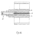
- each endless drive 16 and 17 is integrated in the table top according to FIGS. 7 to 10.
- the first endless drive 16 which consists of several parallel there is synchronously driven round belt drives to outsource articles from a selected one Shaft 4 provided, while the second endless drive 17, which is a chain drive, for storing articles in a selected shaft 4 is determined.
- the second endless drive 17 is in the center according to FIGS. 7 and 10 arranged in the transverse table 15, while the first Endless drive 16 on both sides of the second endless drive 17 runs symmetrically to this drive 17.
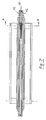
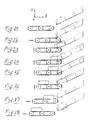
- the second endless drive 17 comprises in the form of a chain drive 6 three equally distributed on the endless circumference protruding article stops 18 which, in FIG. 6 shown hatched, vertically on corresponding link plates 19 of FIG. 12 of the chain drive are attached.
- the article stops 18 perform a dual function, such as will be described below.
- the article stops 18 are in the center according to FIGS. 8, 9 and 11 divided, with both halves of the stop laterally from Chain drive lie so that the return run inside the table the chain can run over drive sprockets.
- the transverse table 15 shows according to FIGS. 6, 7, 10 its two transverse ends in the middle one in plan view narrow operating finger 20, in which also the first and the second endless drive 16, 17 is designed to be integrated.
- the operating finger 20 can outsource a selected one lowest item 2 on the table 15 or when storing an article from table 15 into one selected slot 4 with the bottom of this item in 23, as shown in FIG. 23 in particular to 26 and 37 to 39.
- each shaft 4 of the shelf 3 comprises at the lower shaft side facing the storage and retrieval unit 10 a central recess 21 according to FIG. 13, which is slight is larger than the operating finger 20 in plan view, wherein with a storage and retrieval machine positioned at a lower shaft end the operating finger 20 in the recess without contact is recordable, i.e. non-contact upwards or downwards moved below when the second drive 13 is actuated can be.
- the upright holding tine 22 can be adjusted in height and / or side be trained.
- the upstanding holding tines 22 can also be of shape and size also by means of additional shaped plates or clip-on tines 9, for example according to FIG. 14, can be changed.
- Each shaft top wall 23 is in relation to the holding prong 22 14 is set back on the shelf side and has one upwardly angled edge 24, which the passage of an article at the bottom of the shaft during storage or an outsourcing easier.
- the transverse table 15 has a height-adjustable top of the table Article hold-down and an adjustable Article guiding on each side of the second endless drive 17 in the form of two angled guide rails 25 on, with both guide rails 25 with respect to the transverse axis of the Table 15 synchronously or at the same time adjustable in height and side are.
- the guide rails 25 provide in particular Centering in advance when storing articles in the shaft of the article stop 18 and an alignment of the on the Table 15 stored item 2 before being inserted into the Shelf at a selected location.
- Rollers 26 of the first and second endless drives 16, 17 can be mounted on a common axis 27 according to FIG. 8 his.
- the storage and retrieval machine becomes 10 to that located on the long side of the shelf 3 Transfer point 3 as shown in FIG. 1 via an upstream outlet chute 5 moves, which with respect to the horizontal in is inclined in the opposite direction of the shafts.
- the second drive 13 then the operating finger 20 together with the table is raised so far, that the operating finger is touch-free through the recess 21 arrives and the bottom of the manhole bottom engages underneath and lifts in such a way that Item in the shaft) the second lowest item in the Tray 4 up to the prepositioned articles to be stored slips on the table 15 and the articles due the dead weight of the series of articles against the article stop 18 pushes.
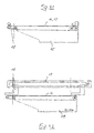
- the second endless drive 17 in one Setting operation taken, the article stop 18 in the direction Shelf 3 up to the operator finger end as shown in Fig. 31, 34 is moved above the table. The article stop pushes 18 the items to be stored 2 in the selected Schacht.
- the storage and retrieval machine 10 not only allows selected ones Articles outsourced from shafts 4, but also to others Shelf space stored, i.e. selected items on the shelf 3 be relocated.
- a removal unit or a transverse one Tables 15 are for one-sided article storage and outsourcing one not illustrated left shelf designed and compared to the aforementioned Version not symmetrical, but asymmetrical educated. Both variants work with one Slider for storing the articles.
- Fig. 41 a chain or toothed belt solution.
- Fig. 42 illustrates a linear unit solution in which the slider is raised with respect to the table conveyor belt the slide motor is correspondingly high. at the latter or the removal finger can be used 20 are very narrow.
- a unilateral removal unit can be used for each shelf side be used, or with a single extraction unit this removal unit is moved around the shelf, to serve both sides of the shelf.
Landscapes
- Engineering & Computer Science (AREA)
- Mechanical Engineering (AREA)
- Warehouses Or Storage Devices (AREA)
Claims (14)
- Automate (1) pour préparer de façon automatique des commandes pour articles (2) comportant :caractérisé en ce que l'autre entraínement est réalisé en tant que deuxième entraínement sans fin (17) guidé par rouleaux et est disposé de façon médiane dans la table s'étendant de façon transversale lorsque le premier entraínement sans fin (16) est disposé de façon symétrique des deux cotés du deuxième entraínement sans fin (17).au moins une étagère (3) pourvue de couloirs (4) disposés l'un sur l'autre et l'un à coté de l'autre ou pourvue de fonds à compartiments ; lesquels couloirs ou fonds s'étendent en direction transversale par rapport à l'étagère tout en étant inclinés dans leurs direction longitudinale par rapport à l'horizontale et dans lesquels fonds à casiers on peut stocker à chaque fois des articles de type identique l'un derrière l'autre,où, lorsqu'on retire ou enlève un article le plus bas dans le couloir, les articles dans le couloir (4) ou dans le fond à casiers peuvent suivrent, etavec un appareil de desserte d'étagère (10) séparé, associé à l'étagère (3), comportant une unité de commande (11) positionnée à chaque extrémité de couloir , commandée par ordinateur et destinée à enlever ou amener des articles (2)et où l'unité de commande (1) de l'appareil de desserte d'étagère peut être déplacée en direction longitudinale de l'étagère par un premier entraínement (12) commandé par ordinateur et peut être réglé en hauteur par un deuxième entraínement (13) commandé par ordinateuret où l'unité de commande (1) comporte une table (15) s'étendant de façon transversale par rapport à la direction longitudinale de l'étagère (3), sur laquelle table on peut entreposer en direction de l'étagère des articles (2) déposés ou enlevés,où la table (15) peut être déplacée de façon transversale par un troisième entraínement (14) commandé par ordinateur en direction transversale de l'étagère etoù on a réalisé dans la table (15) un premier entraínement sans fin (16) s'étendant en direction transversale de l'étagère et guidé par rouleaux et commandé par ordinateur et sur la table (15) un autre entraínement , commandé par ordinateur, pour le transport horizontal d'articles (2) s'étendant en direction transversale de l'étagère, etoù on a prévu le premier entraínement sans fin (16) pour enlever des articles d'un couloir (4) choisi et l'autre entraínement est prévu pour déposer des articles dans un couloir choisi,
- Automate pour préparer de façon automatique des commandes pour articles selon la revendication 1, caractérisé en ce que le deuxième entraínement sans fin (17) comporte au moins une butée (18) d'articles en saillie et de préférence trois butées d'articles (18) reparties de façon régulière sur la circonférence sans fin, que notamment le deuxième entraínement sans fin (17) est un entraínement par chaíne, où la butée d'articles (18) est fixée de façon particulière sur une patte de chaíne (19) de l'entraínement par chaíne, et où la butée d'articles (18) est divisée au milieu, c'est à dire où les deux moitiés de butée sont situées latéralement par rapport à l'entraínement par chaíne, et où notamment le premier entraínement sans fin est un ou plusieurs entraínement par courroie plate synchrones ou des entraínements par courroie ronde synchrones.
- Automate pour préparer de façon automatique des commandes pour articles selon la revendication 1 ou 2, caractérisé en ce qu'on a prévu deux rangées d'étagères droites , faisant faces, éloignées l'une de l'autre, où l'appareil (10) de desserte d'étagère est disposé au milieu en direction longitudinale du couloir d'étagères situé entre les deux rangées d'étagère et où ledit appareil peut être déplacé ou glissé en direction longitudinale de l'étagère (3) et en ce que le premier et deuxième entraínement sans fin (16, 17) sont des entraínements à inversion que l'on peut faire fonctionner de façon indépendante l'un de l'autre dans les deux directions transversales de l'étagère.
- Automate pour préparer de façon automatique des commandes pour articles selon une des revendications 1 à 3, caractérisé en ce que la table (15), s'étendant de façon transversale, comporte au moins à une extrémité au milieu un doigt de desserte dans lequel est intégré un premier et un deuxième entraínement sans fin (16, 17) où on peut introduire le doigt de desserte (20) dans le coté de fond de cet article pendant l'enlèvement d'un article (2) choisi du coté inférieur du couloir ou pendant le dépôt d'un article à partir de la table (15) vers un couloir (4) choisi et en ce que le fond d'un couloir ou chaque fond plat de l'étagère (3) présente sur le coté inférieur du couloir tourné vers l'appareil de desserte d'étagères un évidement central (21) qui est un peu plus grand , vu du dessus, que le doigt de desserte où on peut recevoir , pour un appareil de desserte d'étagères , positionné près de l'extrémité du couloir inférieur, le doigt de desserte (20) sans le toucher dans l'évidement, c'est à dire que l'on peut faire passer doigt de desserte de façon sans le toucher vers le haut et vers le bas.
- Automate pour préparer de façon automatique des commandes pour articles selon une des revendications 1 à 4, caractérisé en ce que l'extrémité inférieure du fond de couloir comporte au moins une pointe de maintient (22) debout qui peut être réglé de préférence en hauteur et / ou latéralement, et en ce que notamment la paroi (23) de couverture de couloir est décalée en arrière , du coté de l'étagère, par rapport à la pointe de maintient et comporte au bord (24) formant un angle vers le haut et en ce qu'on a prévu dans la zone de plafond d'un fond plat un dispositif de maintient de niveau haut formant un angle vers le haut et décalé vers l'arrière du coté de l'étagère par rapport à la pointe de maintient debout.
- Automate pour préparer de façon automatique des commandes pour articles selon une des revendications 1 à 5, caractérisé en ce que la table (15) comporte un dispositif de centrage de butée d'articles et / ou un guidage latéral réglable pour les articles et / ou un dispositif de maintient de niveau haut réglable en hauteur pour les articles, où notamment le dispositif de maintient de niveau haut d'articles, réglable en hauteur, et le guidage latéral d'articles, réglable en hauteur, sont un rail de guidage (25) formant un angle sur chaque coté du deuxième entraínement sans fin (17), et en ce que les deux rails de guidage (25) peuvent être réglés de façon synchrone ou simultanée par rapport à l'axe transversal de la table (15).
- Procédé pour enlever automatiquement des articles du stock au moyen d'un automate de préparation de commandes selon une des revendications 1 à 6, où on a stocké des articles de façon contiguë l'un derrière l'autre dans des couloirs inclinés de l'étagère et où on bloque à l'extrémité inférieure du couloir, à chaque fois, l'article le plus en bas de couloir contre une sortie du couloir au moyen d'une pointe de maintient fixe,
caractérisé en ce que l'on déplacé l'appareil de commande d'étagère (10) au moyen d'un premier, deuxième et troisième entraínement commandés par ordinateurs vers l'extrémité inférieure du couloir choisi (4) et qu'on positionne le doigt de desserte (20) en dessous de l'extrémité du couloir en dessous de l'évidement et en ce que l'on lève et descend au moyen du deuxième entraínement (13) , lorsque le premier entraínement (16) sans fin fonctionnant en permanence est en service, l'unité de commande avec la table (15) et le doigt de desserte (20) de manière telle que le doigt de desserte (20) arrive sans toucher à travers l'évidement (21) et saisit à ce moment, du coté du fond, par en dessous l'article le plus bas du couloir et le soulève, puis le baisse de manière à ce que le deuxième article le plus bas dans le couloir, éventuellement avec d'autres articles présents dans le couloir, glisse jusqu'à la pointe (22) de maintient et en ce que l'on transporte l'article, qui était auparavant le plus bas, au moyen du premier entraínement (16) sans fin en direction transversale loin de l'étagère et qu'on le place ensuite sur la table (15) jusqu'à une butée d'articles positionnée sur l'autre table au moyen d'un service de réglage du deuxième entraínement (17) sans fin , disposé dans la direction de transport au milieu entre les deux premiers parties d'entraínement sans fin, l'unité de commande (11) est ensuite déplacée au moyen du troisième entraínement (14) vers une position neutre loin de l'étagère. - Procédé selon la revendication 7, caractérisé en ce que l'on approche et dessert encore une fois le même couloir ou un autre couloir choisi jusqu'à ce que la commande d'enlèvement et de préparation de commande soit terminée et que la table soit remplie complètement d'articles enlevés.
- Procédé selon la revendication 7 ou 8, caractérisé en ce que l'appareil de commande d'étagère (10) est déplacé vers un endroit de transfert (3) situé du coté longitudinal de l'étagère (3) ou entre deux étagères, à l'endroit duquel on sort , en actionnant le premier ou deuxième entraínement sans fin (16, 17), les articles entreposés sur la table (15) vers un conteneur de réception et / ou un convoyeur à bande ou un couloir de sortie (5).
- Procédé selon une des revendications 7 à 9, de préparation d'articles au moyen d'un automate de préparation d'articles entre au moins deux étagères opposées et dont l'une est espacée de l'autre, caractérisé en ce que l'on inverse au moins , lorsqu'on fait fonctionner l'étagère opposée , la marche du premier entraínement sans fin (16) et en ce que l'on positionne la butée d'articles (18) du deuxième entraínement sans fin (17) sur l'autre coté transversal de la table.
- Procédé pour déposer automatiquement des articles au moyen d'un automate de préparation d'articles selon une des revendications 1 à 6, caractérisé en ceque l'on positionne et centre éventuellement au moyen d'un centreur fermé la butée d'articles (18) du deuxième entraínement sans fin sur le coté supérieur de la table, loin de l'étagère, en direction de transport au milieu entre les deux parties d'entraínement du premier entraínement sans fin,en ce que l'on oriente de façon médiane les articles à déposer l'un derrière l'autre sur le coté supérieur de la table en réglant le guidage latéral d'article et en ce que l'on guide les articles en hauteur au moyen d'un dispositif de maintien de niveau haut,en ce que l'on déplace les articles, au moyen d'une butée d'articles (18), vers l'avant dans une position de dépôt sur la table près de l'étagère, où on maintient le doigt de desserte (20) sans qu'il touche des articles,en ce que l'on positionne le doigt de desserte (20) en dessous de l'évidement (21) du couloir choisi en actionnant le premier, deuxième et troisième entraínement,en ce que l'on soulève le doigt de desserte (20) avec la table jusqu'à ce que le doigt de desserte arrive sans toucher à travers l'évidemment (21) et saisit à ce moment, du coté du fond, par en dessous l'article le plus bas du couloir et le soulève de manière telle que le deuxième article (4) le plus bas dans le couloir glisse sur la table (15) jusqu'aux articles prépositionnés à déposer et pousse ces articles contre la butée (18) d'articles,en ce que le deuxième entraínement sans fin (17) fonctionne en mode de réglage et déplace sur le coté supérieur de la table la butée d'articles (18) en direction de l'étagère (3) directement jusqu'à l'extrémité du doigt de desserte et pousse en même temps les articles à déposer dans le choisi,en ce que l'on règle, au moyen du deuxième entraínement (13), le doigt de desserte avec la table vers le bas, en ce que le doigt arrive sans toucher, à travers l'évidement (21) et que les articles (2) glissent dans le couloir (4) contre la pointe (22), selon quoi on déplace l'unité de commande (11) au moins par le troisième entraínement (14) vers une position neutre loin de l'étagère.
- Procédé selon la revendication 11, caractérisé en ce que l'on approche et dessert encore une fois le même couloir ou un autre couloir choisi jusqu'à ce que la commande de dépôt soit terminée.
- Procédé selon une des revendications 11 ou 12, de préparation d'articles au moyen d'un automate entre au moins deux étagères opposées et dont l'une est espacée de l'autre,
caractérisé en ce que l'on inverse latéralement le fonctionnement de la table (15), lorsqu'on fait fonctionner l'étagère opposée , et en ce que l'on positionne , avant l'introduction des articles dans le couloir, la butée d'articles (18) du deuxième entraínement sans fin (17) sur l'autre coté transversal de la table. - Procédé selon une des revendications 7 à 13, caractérisé en ce que l'on retire du couloir (4) des articles choisis au moyen de l'appareil de commande d'étagère (10) et qu'on les déposent à d'autres endroits de l'étagère, c'est à dire que l'on change la place des articles choisis sur l'étagère (3).
Applications Claiming Priority (2)
| Application Number | Priority Date | Filing Date | Title |
|---|---|---|---|
| DE19714455A DE19714455A1 (de) | 1997-02-24 | 1997-02-24 | Verfahren und Vorrichtung zum automatischen Kommissionieren von Artikeln |
| DE19714455 | 1997-02-24 |
Publications (3)
| Publication Number | Publication Date |
|---|---|
| EP0866002A2 EP0866002A2 (fr) | 1998-09-23 |
| EP0866002A3 EP0866002A3 (fr) | 1999-12-15 |
| EP0866002B1 true EP0866002B1 (fr) | 2003-05-07 |
Family
ID=7825783
Family Applications (1)
| Application Number | Title | Priority Date | Filing Date |
|---|---|---|---|
| EP98103108A Expired - Lifetime EP0866002B1 (fr) | 1997-02-24 | 1998-02-23 | Méthode et dispositif pour préparer automatiquement des commandes d'articles |
Country Status (3)
| Country | Link |
|---|---|
| EP (1) | EP0866002B1 (fr) |
| AT (1) | ATE239651T1 (fr) |
| DE (2) | DE19714455A1 (fr) |
Cited By (1)
| Publication number | Priority date | Publication date | Assignee | Title |
|---|---|---|---|---|
| CN101054127B (zh) * | 2007-05-18 | 2011-07-20 | 苏州艾隆科技有限公司 | 斜坡式储药库 |
Families Citing this family (9)
| Publication number | Priority date | Publication date | Assignee | Title |
|---|---|---|---|---|
| DE10021365C2 (de) * | 2000-05-02 | 2002-06-13 | P & P Materialflussysteme Gmbh | Bedienanordnung zum Bedienen eines Produktlagerregals, insbesondere einer Kommissioniervorrichtung |
| DE10130984B4 (de) * | 2001-06-27 | 2004-03-25 | Knapp Logistik Automation Ges.M.B.H. | Regalbediengerät und Verfahren zum Bedienen eines Produktlagerregals insbesondere einer Kommissioniervorrichtung |
| ITMI20051727A1 (it) * | 2005-09-19 | 2007-03-20 | Bottigelli Service S R L | Dispositivo di immagazzinamento e di prelievo di prodotti e suo procedimento di gestione |
| US7686560B2 (en) * | 2005-12-08 | 2010-03-30 | Conestoga Cold Storage | Rack, conveyor and shuttle automated pick system |
| EP1806302A1 (fr) * | 2006-01-05 | 2007-07-11 | von Liechtenstein, Alexander | Procede et dispositif de préparation de commandes et de stockage |
| CN102390652A (zh) * | 2011-07-19 | 2012-03-28 | 江苏迅捷装具科技有限公司 | “h”形储物槽及组合式储物架 |
| AT512970A1 (de) * | 2012-04-11 | 2013-12-15 | Knapp Systemintegration Gmbh | Verfahren und Vorrichtung zur Sortierung von Gütern, insbesondere Getränkekisten |
| CN107176405B (zh) * | 2016-03-10 | 2023-10-10 | 周兆弟 | 一种建材自动存放装置 |
| US20240005270A1 (en) * | 2022-07-02 | 2024-01-04 | Printec Bulgaria Jsc | Increasing the capacity of different types of products and matching stock with forecasted sales volumes per product type in automatic vending machines |
Family Cites Families (6)
| Publication number | Priority date | Publication date | Assignee | Title |
|---|---|---|---|---|
| US3750804A (en) * | 1969-03-07 | 1973-08-07 | Triax Co | Load handling mechanism and automatic storage system |
| GB2205822A (en) * | 1987-06-18 | 1988-12-21 | Supac Systems Inc | Container extraction and transfer mechanism for an automated storage and retrieval system |
| DE9301797U1 (de) * | 1993-02-09 | 1993-07-22 | Frazier Industrial Co., Long Valley, N.J. | Lagergestell |
| US5551823A (en) * | 1993-08-20 | 1996-09-03 | Tsubakimoto Chain Co. | Transfer apparatus having traction pin moved with height difference |
| DE9409881U1 (de) * | 1994-06-18 | 1994-09-15 | P+P Materialflußsysteme GmbH, 04626 Schmölln | Kommissionieranlage |
| DE29703230U1 (de) * | 1997-02-24 | 1997-07-31 | P + P Materialfluß-Systeme GmbH, 04626 Schmölln | Kommissionierautomat zum automatischen Kommissionieren von Artikeln |
-
1997
- 1997-02-24 DE DE19714455A patent/DE19714455A1/de not_active Withdrawn
-
1998
- 1998-02-23 EP EP98103108A patent/EP0866002B1/fr not_active Expired - Lifetime
- 1998-02-23 DE DE59808215T patent/DE59808215D1/de not_active Expired - Fee Related
- 1998-02-23 AT AT98103108T patent/ATE239651T1/de not_active IP Right Cessation
Cited By (1)
| Publication number | Priority date | Publication date | Assignee | Title |
|---|---|---|---|---|
| CN101054127B (zh) * | 2007-05-18 | 2011-07-20 | 苏州艾隆科技有限公司 | 斜坡式储药库 |
Also Published As
| Publication number | Publication date |
|---|---|
| DE19714455A1 (de) | 1998-09-03 |
| EP0866002A2 (fr) | 1998-09-23 |
| EP0866002A3 (fr) | 1999-12-15 |
| ATE239651T1 (de) | 2003-05-15 |
| DE59808215D1 (de) | 2003-06-12 |
Similar Documents
| Publication | Publication Date | Title |
|---|---|---|
| DE19509951C2 (de) | Vorrichtung zum unsortierten Lagern von Waren oder sonstigen Gegenständen | |
| DE4336885A1 (de) | Kommissionierungsanlage für Apothekenprodukte | |
| EP1820754A2 (fr) | Système d'étagère et procédé de stockage automatisé de petits objets | |
| EP0866002B1 (fr) | Méthode et dispositif pour préparer automatiquement des commandes d'articles | |
| DE202012012928U1 (de) | Vorrichtung zum Lagern von Waren, insbesondere Arzneimitteln | |
| DE3830373A1 (de) | Automatisch arbeitendes lager- und transportsystem zur ver- und entsorgung von arbeitsplaetzen | |
| DE19812147A1 (de) | Kommissionieranlage mit Schnelldrehautomat und Regalbediengerät | |
| EP2199229A2 (fr) | Moyen de réception de charge pour un appareil de commande de rayonnage, installation de transport dotée d'un appareil de commande de rayonnage et procédé de fonctionnement de l'installation de transport | |
| EP1762511B1 (fr) | Entrepôt automatique avec transstockeur avec gaine tampon et méthode d'opération d'un tel entrepôt | |
| DE102004025070B4 (de) | Verfahren und Vorrichtung zur Einlagerung von Waren in eine automatisierte Lagervorrichtung | |
| EP0062233B1 (fr) | Convoyeur de marchandises pour l'expédition avec stations de transfert disposées successivement dans la direction de transport | |
| EP2163491B1 (fr) | Automate de stockage | |
| DE102015113401A1 (de) | Ausgabeeinheit für Backwaren | |
| EP0496992A1 (fr) | Dispositif de chargement et déchargement d'un plateau support | |
| DE10130984B4 (de) | Regalbediengerät und Verfahren zum Bedienen eines Produktlagerregals insbesondere einer Kommissioniervorrichtung | |
| DE102004059809B4 (de) | Verfahren und Vorrichtung zur Bestückung und Entnahme von Lagergut aus Regalfächern eines Lagerregals | |
| DE29703230U1 (de) | Kommissionierautomat zum automatischen Kommissionieren von Artikeln | |
| EP0869084B1 (fr) | Installation d'emmagasinage avec supports pour transporter des matériaux et dispositif pour la manipulation des supports | |
| EP0416627B1 (fr) | Procédé et dispositif pour stocker et reprendre automatiquement des sortes de marchandises de détail de rayonnages dans de grands entrepôts | |
| DE10015272C2 (de) | Vorrichtung zum Ein- und Auslagern von Laststrägern in einem Regallager | |
| EP1652799B1 (fr) | Dispositif pour individualiser des marchandises | |
| EP2163492A2 (fr) | Entrepôt combiné | |
| EP0560206B1 (fr) | Aménagement d'entrepÔt pour le ramassage automatique d'articles | |
| WO1997042110A1 (fr) | Procede et dispositif pour stocker, grouper et transporter des produits, notamment des biscuits | |
| DE19618918C2 (de) | Kommissionierautomat zum automatischen Kommissionieren und Versandbereitstellen von gestapelten Artikeln |
Legal Events
| Date | Code | Title | Description |
|---|---|---|---|
| PUAI | Public reference made under article 153(3) epc to a published international application that has entered the european phase |
Free format text: ORIGINAL CODE: 0009012 |
|
| AK | Designated contracting states |
Kind code of ref document: A2 Designated state(s): AT BE CH DE ES FR GB IT LI NL |
|
| AX | Request for extension of the european patent |
Free format text: AL;LT;LV;MK;RO;SI |
|
| PUAL | Search report despatched |
Free format text: ORIGINAL CODE: 0009013 |
|
| AK | Designated contracting states |
Kind code of ref document: A3 Designated state(s): AT BE CH DE DK ES FI FR GB GR IE IT LI LU MC NL PT SE |
|
| AX | Request for extension of the european patent |
Free format text: AL;LT;LV;MK;RO;SI |
|
| 17P | Request for examination filed |
Effective date: 20000426 |
|
| AKX | Designation fees paid |
Free format text: AT BE CH DE ES FR GB IT LI NL |
|
| 17Q | First examination report despatched |
Effective date: 20010821 |
|
| GRAH | Despatch of communication of intention to grant a patent |
Free format text: ORIGINAL CODE: EPIDOS IGRA |
|
| GRAH | Despatch of communication of intention to grant a patent |
Free format text: ORIGINAL CODE: EPIDOS IGRA |
|
| GRAH | Despatch of communication of intention to grant a patent |
Free format text: ORIGINAL CODE: EPIDOS IGRA |
|
| GRAA | (expected) grant |
Free format text: ORIGINAL CODE: 0009210 |
|
| AK | Designated contracting states |
Designated state(s): AT BE CH DE ES FR GB IT LI NL |
|
| PG25 | Lapsed in a contracting state [announced via postgrant information from national office to epo] |
Ref country code: NL Free format text: LAPSE BECAUSE OF FAILURE TO SUBMIT A TRANSLATION OF THE DESCRIPTION OR TO PAY THE FEE WITHIN THE PRESCRIBED TIME-LIMIT Effective date: 20030507 Ref country code: GB Free format text: LAPSE BECAUSE OF FAILURE TO SUBMIT A TRANSLATION OF THE DESCRIPTION OR TO PAY THE FEE WITHIN THE PRESCRIBED TIME-LIMIT Effective date: 20030507 |
|
| REG | Reference to a national code |
Ref country code: GB Ref legal event code: FG4D Free format text: NOT ENGLISH |
|
| REG | Reference to a national code |
Ref country code: CH Ref legal event code: EP |
|
| REF | Corresponds to: |
Ref document number: 59808215 Country of ref document: DE Date of ref document: 20030612 Kind code of ref document: P |
|
| PG25 | Lapsed in a contracting state [announced via postgrant information from national office to epo] |
Ref country code: ES Free format text: LAPSE BECAUSE OF FAILURE TO SUBMIT A TRANSLATION OF THE DESCRIPTION OR TO PAY THE FEE WITHIN THE PRESCRIBED TIME-LIMIT Effective date: 20030818 |
|
| NLV1 | Nl: lapsed or annulled due to failure to fulfill the requirements of art. 29p and 29m of the patents act | ||
| GBV | Gb: ep patent (uk) treated as always having been void in accordance with gb section 77(7)/1977 [no translation filed] |
Effective date: 20030507 |
|
| PG25 | Lapsed in a contracting state [announced via postgrant information from national office to epo] |
Ref country code: AT Free format text: LAPSE BECAUSE OF NON-PAYMENT OF DUE FEES Effective date: 20040223 |
|
| PG25 | Lapsed in a contracting state [announced via postgrant information from national office to epo] |
Ref country code: BE Free format text: LAPSE BECAUSE OF NON-PAYMENT OF DUE FEES Effective date: 20040228 |
|
| PG25 | Lapsed in a contracting state [announced via postgrant information from national office to epo] |
Ref country code: LI Free format text: LAPSE BECAUSE OF NON-PAYMENT OF DUE FEES Effective date: 20040229 Ref country code: CH Free format text: LAPSE BECAUSE OF NON-PAYMENT OF DUE FEES Effective date: 20040229 |
|
| PLBE | No opposition filed within time limit |
Free format text: ORIGINAL CODE: 0009261 |
|
| STAA | Information on the status of an ep patent application or granted ep patent |
Free format text: STATUS: NO OPPOSITION FILED WITHIN TIME LIMIT |
|
| ET | Fr: translation filed | ||
| 26N | No opposition filed |
Effective date: 20040210 |
|
| BERE | Be: lapsed |
Owner name: *P+P MATERIALFLUSS-SYSTEME G.M.B.H. Effective date: 20040228 |
|
| PG25 | Lapsed in a contracting state [announced via postgrant information from national office to epo] |
Ref country code: DE Free format text: LAPSE BECAUSE OF NON-PAYMENT OF DUE FEES Effective date: 20040901 |
|
| REG | Reference to a national code |
Ref country code: CH Ref legal event code: PL |
|
| PG25 | Lapsed in a contracting state [announced via postgrant information from national office to epo] |
Ref country code: FR Free format text: LAPSE BECAUSE OF NON-PAYMENT OF DUE FEES Effective date: 20041029 |
|
| REG | Reference to a national code |
Ref country code: FR Ref legal event code: ST |
|
| PG25 | Lapsed in a contracting state [announced via postgrant information from national office to epo] |
Ref country code: IT Free format text: LAPSE BECAUSE OF NON-PAYMENT OF DUE FEES Effective date: 20050223 |