EP0866014B1 - Bobinoir automatique - Google Patents
Bobinoir automatique Download PDFInfo
- Publication number
- EP0866014B1 EP0866014B1 EP19980105230 EP98105230A EP0866014B1 EP 0866014 B1 EP0866014 B1 EP 0866014B1 EP 19980105230 EP19980105230 EP 19980105230 EP 98105230 A EP98105230 A EP 98105230A EP 0866014 B1 EP0866014 B1 EP 0866014B1
- Authority
- EP
- European Patent Office
- Prior art keywords
- yarn
- automatic winder
- hairiness
- winder according
- capsule
- Prior art date
- Legal status (The legal status is an assumption and is not a legal conclusion. Google has not performed a legal analysis and makes no representation as to the accuracy of the status listed.)
- Expired - Lifetime
Links
- 239000002775 capsule Substances 0.000 claims description 50
- 206010020112 Hirsutism Diseases 0.000 claims description 44
- 239000000919 ceramic Substances 0.000 claims description 2
- 238000004804 winding Methods 0.000 description 6
- 238000010586 diagram Methods 0.000 description 2
- 238000004140 cleaning Methods 0.000 description 1
- 239000000428 dust Substances 0.000 description 1
- 238000005516 engineering process Methods 0.000 description 1
- 239000002783 friction material Substances 0.000 description 1
- 238000000034 method Methods 0.000 description 1
- 230000000737 periodic effect Effects 0.000 description 1
- 238000009987 spinning Methods 0.000 description 1
Images


Classifications
-
- D—TEXTILES; PAPER
- D01—NATURAL OR MAN-MADE THREADS OR FIBRES; SPINNING
- D01H—SPINNING OR TWISTING
- D01H7/00—Spinning or twisting arrangements
- D01H7/92—Spinning or twisting arrangements for imparting transient twist, i.e. false twist
- D01H7/923—Spinning or twisting arrangements for imparting transient twist, i.e. false twist by means of rotating devices
-
- B—PERFORMING OPERATIONS; TRANSPORTING
- B65—CONVEYING; PACKING; STORING; HANDLING THIN OR FILAMENTARY MATERIAL
- B65H—HANDLING THIN OR FILAMENTARY MATERIAL, e.g. SHEETS, WEBS, CABLES
- B65H54/00—Winding, coiling, or depositing filamentary material
- B65H54/70—Other constructional features of yarn-winding machines
- B65H54/705—Arrangements for reducing hairyness of the filamentary material
-
- B—PERFORMING OPERATIONS; TRANSPORTING
- B65—CONVEYING; PACKING; STORING; HANDLING THIN OR FILAMENTARY MATERIAL
- B65H—HANDLING THIN OR FILAMENTARY MATERIAL, e.g. SHEETS, WEBS, CABLES
- B65H59/00—Adjusting or controlling tension in filamentary material, e.g. for preventing snarling; Applications of tension indicators
- B65H59/10—Adjusting or controlling tension in filamentary material, e.g. for preventing snarling; Applications of tension indicators by devices acting on running material and not associated with supply or take-up devices
- B65H59/20—Co-operating surfaces mounted for relative movement
- B65H59/22—Co-operating surfaces mounted for relative movement and arranged to apply pressure to material
-
- B—PERFORMING OPERATIONS; TRANSPORTING
- B65—CONVEYING; PACKING; STORING; HANDLING THIN OR FILAMENTARY MATERIAL
- B65H—HANDLING THIN OR FILAMENTARY MATERIAL, e.g. SHEETS, WEBS, CABLES
- B65H2701/00—Handled material; Storage means
- B65H2701/30—Handled filamentary material
- B65H2701/31—Textiles threads or artificial strands of filaments
Definitions
- the present invention relates to an automatic winder according to the preamble of claim 1.
- a winder of this type that controls the hairiness of spun yarn by providing the yarn with a false twist through a pair of soft, barrel-shaped rotating drums positioned so as to intersect and form a nip point in the yarn path is disclosed in JP-81 88 332.
- the rotation speed of the soft, barrel-shaped rotating drums in this kind of a conventional winder is limited, and the winder thus has difficulty winding at speeds over 1000m/minute.
- the pair of rotating drums that nip the yarn and provide the false twist function as a kind of feed roller that actively feeds out the yarn at a fixed speed, they pose problems for winders that form a cone package wherein the yarn speed must differ at the opposite ends of the wound package.
- the present invention is defined by the features of the characterizing portion of claim 1.
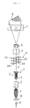
- 1 is a supply bobbin like a spinning bobbin arranged on a bobbin tray 1a
- 2 is a vertically moveable balloon control tube
- 3 is a hairiness control member comprised of a capsule member C which is allowed to contact the yarn unwound from the supply bobbin 1
- 5 is a container member, which houses the capsule member C
- 4 is a disk-type friction false twisting device in which three vertical shafts 4a are arranged at points forming an equilateral triangle, each of said vertical shafts is attached to friction disks 4b.
- the friction disks 4b are arranged on a different planes. Moreover, when seen in a planar view, the disks 4b may be overlapped partially.
- a third vertical shaft with attached friction disks located in the middle behind the two vertical shafts 4a shown in the diagram, has been omitted.
- the false-twisting device is arranged such that by rotating the three vertical shafts in the same direction, a yarn y, which runs zig-zag-like between the friction disks 4b, is imparted a false twist.
- the outer surface of the friction discs 4b which contacts the yarn y should preferably be comprised of low-friction materials like ceramics in order to prevent hariness.
- 5 is an automatic yarn-splicing device
- 6 is a yarn clearer
- 7 is a traverse drum
- 8 is a for example cone-shaped wound package.
- 9 is an air ejection nozzle arranged below the supply bobbin 1 to blow the tip of yarn y inserted inside the hole of newly supplied supply bobbin 1 upwards toward the hairiness control member 3.
- the yarn clearer 6 may also be positioned in front of the automatic yarn-splicing device 5.
- the hairiness control member 3 which comprises the capsule member C and the container member S that houses the capsule member C, and is positioned on the supply bobbin 1 side of the false twisting device 4, will now be explained.
- s1 is an outer tube provided with a flange section s2 on the upper end, and into the lower end of which the small-diameter upper end section s5 of a yarn guiding member s4, in which a tapered yarn guide hole s3 which gradually widens in a descending direction is formed, is engaged. Further, a slit s6 which extends to the upper end of the outer tube s1 is formed in the flange section s2.
- s7 is a tubular holding member provided with a tapered hole s8 that widens in the upward direction, and which is inserted into outer tube s1.
- the moveable holding member s9 is a vertically moveable holding member inserted into the slit s6 formed in the above-described outer tube s1 and flange s2.
- the moveable holding member s9 is comprised of beam-shaped stopper s10 which is slightly longer than the outer radius of the outer tube s1, and tubular shaped holding tube s11 which is affixed to about the center of stopper s10.
- the inner yarn passage s15 inside the holding tube s11 is comprised of tapered opening s12 which widens downwardly tubular opening s13 which is located below and connects to the large diameter section of tapered opening s12 above, and tubular opening s14 which is located above and connects to the small diameter section of tapered opening s12 below.
- s16 is an air hole opened in a vertical direction and running between the guiding member s4 and the flange section s2 of outer tube s1.
- Lateral air hole s17, opened in flange section s2 and connected to air hole s16, is provided with a pipe that is connected to high pressure air supply source (not shown).
- lateral air hole s18, opened in guiding member s4 and connecting to air hole s16 is provided with exit hole s18' which exits facing in the direction of capsule member C held in container member S.
- Capsule member C comprises an upper capsule body c1 and lower capsule body c2 which fit one inside the other, and a coiled spring c3 which applies force in opposing directions against upper capsule body c1 and lower capsule body c2.
- Upper capsule body c1 and lower capsule body c2 are arranged so as to be able to slide against each other, and the upper end of upper capsule body c1 and the lower end of lower capsule body c2 each form hemispheres.
- Capsule member C is contained inside the outer tube s1 of the container member S.
- the lower part of the lower capsule body c2 is inserted into the holding member s7 on the inside of outer tube s1 formed by tapered hole s8.
- moveable holding member s9 is inserted into slit s6 which is formed in outer tube s1 and flange section s2 such that the tapered hole s12 and the tubular hole s13 that form the inner yarn path s15 of the holding member s11 the top part of capsule member C.
- the capsule member C contained inside the outer tube s1 of the container member S is formed such that the holding member s6 and holding member s9 inserted inside the slit s6 fit into each other and engage inside outer tube s1.
- capsule member C contained inside container member S on the inside of outer tube s1 is held by holding member s7, which itself is engaged with the inside of outer tube s1, and moveable holding member s9 which in turn is inserted inside slit s6.
- a curved interstice is formed between the outer surface of capsule member C and the moveable holding member s9, and between the outer surface of capsule member C and the inner surface of outer tube s1 such that the yarn is able to pass through.
- Capsule member C which is stored inside the container member S on the inside of outer tube s1 is arranged such that moveable member s9 which is inserted into slit s6 and holding member s7 engaged with the inside of outer tube s1, functions to compress coil spring c3 which is arranged between the upper capsule body c1 and the lower capsule body c2. Consequentially, the lower part of lower capsule body c2 comes into contact with the slanted surface s7' formed by tapered hole s8 of the holding member s7 which itself is engaged with the inside of outer tube s1. Further, the upper part of the upper capsule body c1 comes into contact with the slanted surface s12' formed by tapered hole s12 of moveable holding member s9 of holding member s11.
- Yarn y is led from tapered yarn guide hole s3 of yarn guiding member s4, between the slanted surface s7' which is formed in the hole s8 of the holding member s7 and the bottom of the lower capsule body c2 of the capsule C which is in contact with the slanted surface s7' through the weight of the coil spring arranged inside the capsule member C and the weight of the capsule member C itself.
- the yarn y passes the tubular passage 10, and then between the upper part of the upper capsule body c1 of capsule member C which is in contact with the slanted surface s12' of hole s12 formed in the moveable holding member s9 of holding member s11, said contact induced by means of-coil spring c3 arranged inside the capsule member C, and slanted surface s12'.
- the yarn is then passed out above moveable holding member s9.
- the yarn y drawn out from supply bobbin 1 passes through the balloon control tube 2 and the hairiness control member 3, and is supplied to the false twisting device 4 located above the hairiness control member 3.
- the yarn is then passed through the yarn-splicing device 5 and the yarn clearer 6, and is wound into a package 8 as it is traversed by way of traverse drum 7.
- the running yarn is imparted a false twist which spreads downwardly from the false twisting device 4.
- the hairiness control member 3 meaning that the hairiness control device 3 also functions as a twist transmission-stopping member, thus enabling yarn Y to be effectively twisted. Hairiness is thus prevented through the imparting of a false twist to yarn y, whereby the hairiness on the surface of yarn Y is twisted into the yarn.
- Moveable holding member s9 at the point where it is not pulled completely out of slit 6, after moveable holding member s9 is lifted, stops the rise of balloon control tube 2. Thereby, the lifting of moveable holding member s9 causes an interstice to be formed between the slanted surface s12' of the tapered hole s12 of the holding tube s11 of the moveable holding member s9 and the-upper capsule body c1 of capsule C such that the yarn y can pass through.
- the air ejection nozzle 9 arranged below the supply bobbin 1 is activated, causing the end of the yarn which has been inserted into the hole of the supply bobbin 1 to be blown upwards from the top of the hole of the supply bobbin 1.
- a high-pressure air supply (not shown)
- air is ejected from exit hole s18' in the direction of the capsule member C, thus creating an upward air current inside hairiness control member 3.
- the yarn blown upwards from the top hole of supply bobbin 1 is passed through the interstice between the bottom of the lower capsule body c2 of the capsule member C which is floated up by the high pressured air, and the slanted surface s7' of the holding member s7 inserted in outer tube s1.
- the yarn is then passed through the tubular passage 10 and then through the interstice formed between the slanted surface s12' of the tapered hole s12 formed in the holding tube s11 of the moveable holding member s9, and the upper capsule body c1 of the capsule member C.
- the yarn then is drawn out of the top of the hairiness control member 3, completing the passage.
- the yarn passage through the hairiness control member 3 occurs by the supply of high pressured air from the high pressured air supply source (not shown) through the air ejection hole s19 opening into the container member S, but the air supplied through air ejection hole s19 can be low pressure air, and by creating an upward flow of air at the the tubular passage 10 of hairiness control member 3, fluff that has collected in the hairiness control device 3 can still be removed.
- the embodiment described above is arranged such that the balloon control tube 2 is raised into the moveable holding member s9 when a new supply bobbin 1 is supplied, but the present invention can also be arranged such that the moveable holding member s9 is raised without the balloon control tube 2 being raised, using a completely separate machanism like a lever member.
- the present invention it is possible to reduce of eliminate the hairiness of spun yarn wound into a package. Further, the present invention enables a cone package to be wound at high speeds (above 1000m/ minute) while still preventing hairiness, and without negatively affecting the winding process. Still further, the disk-type friction false twisting device allows easy yarn threading, which permits automatic yarn splicing. Further still, the present invention enables the yarn tension to be controlled without the need for providing a separate yarn tensor.
- the present invention allows an effective reduction of hairiness. Further, the present invention allows the hairiness to be even more effectively reduced at high winding speeds, and yarn threading during yarn splicing is made easier.
- the capsule member Since the capsule member is held by the moveable holding member by moving the movable holding member when the yarn is passed through the hairiness control member, moving the capsule member becomes easy, and consequentially, the passing of the yarn through the hairiness control member is accomplished rapidly and reliably.
- the moveable holding member is moved by the balloon control tube, it is unnecessary to supply a special separate moving device, and it becomes possible to move the moveable holding member when the yarn is passed through the hairiness control member.
- the capsule When yarn is passed through the hairiness control member, by creating an air flow in an upward direction through the inside of the hairiness control member, the capsule is forced to float upwards, creating an interstice inside the hairiness control member through which the yarn can pass. Consequentially, it is possible to automate the passage of yarn through the hairiness control member. Furthermore, using this air flow, clearance of the fluff accumulated inside the hairiness control device whenever the supply bobbin is changed is enabled, allowing for cleaning of the hairiness control member each time, and reliably preventing decrease in the machine's performance.
Landscapes
- Engineering & Computer Science (AREA)
- Textile Engineering (AREA)
- Mechanical Engineering (AREA)
- Spinning Or Twisting Of Yarns (AREA)
- Guides For Winding Or Rewinding, Or Guides For Filamentary Materials (AREA)
- Forwarding And Storing Of Filamentary Material (AREA)
- Tension Adjustment In Filamentary Materials (AREA)
Claims (13)
- Bobinoir automatique, dans lequel un fil (y) déroulé d'une bobine d'alimention (1) est enroulé sur une structure de bobinage (8) comportant un dispositif de fausse torsion (4) pour contrôler la pilosité du fil, caracterisé en ce que le dispositif de fausse torsion est un dispositif de fausse torsion (4) du type à disque de friction prévu dans le chemin du fil s'étendant de la bobine d'alimentation à la structure de bobinage.
- Bobinoir automatique selon la revendication 1, caracterisé en ce qu'un élément de contrôle de pilosité (3) est prévu entre le dispositif de fausse torsion (4) et la bobine d'alimentation (1).
- Bobinoir automatique selon la revendication 2, caracterisé en ce que l'élément de contrôle de pilosité (3) comporte un tenseur de capsule (C) qui est élastiquement en contact avec des surfaces environnantes (s7', S12') formant ensemble au moins partiellement un chemin de fil.
- Bobinoir automatique selon la revendication 3, caracterisé en ce que le tenseur de capsule (C) se trouve dans un tube extérieur (S1) d'un élément (S) déstiné à le contenir.
- Bobinoir automatique selon la revendication 4, caracterisé en ce que la partie inférieure du tenseur de capsule (S) est logée dans un élément de maintien tubulaire (7) inséré dans le tube externe (S1) et présentant un trou conique (s8) qui s'élargit vers l'intérieur, et dont la partie supérieure est contactée par un élément de maintien déplaçable verticalement (s9) présentant une ouverture conique (s12) qui s'élargit vers l'intérieur.
- Bobinoir automatique selon la revendication 5, caracterisé en ce que l'élément de maintien (s9) est inséré dans une fente (s6) ménagée dans le tube externe (s1).
- Bobinoir automatique selon la revendication 5 ou 6, caracterisé en ce que l'élément de maintien mobile (s9) comprend une butée d'arrêt (s10) configurée en poutre.
- Bobinoir automatique selon les revendications 4 à 7, caracterisé en ce que le tenseur de capsule (C) est constitué de deux corps de capsule (c1, c2), s'adaptant l'un dans l'autre, qui sont mobiles relativement et qui contiennent un élément élastique.
- Bobinoir automatique selon la revendication 8, caracterisé en ce que l'élément élastique est un ressort helicoïdal (c3).
- Bobinoir automatique selon la revendication 6 ou 7, caracterisé en ce que l'élément de maintien (s9) fait saillir du tube externe (s1).
- Bobinoir automatique selon les revendications 4 à 10, caracterisé par un canal d'air (s17, s18, s18', s19) s'ouvrant dans la partie inférieure du tenseur de capsule (C) .
- Bobinoir automatique selon la revendication 10, caracterisé par un tube de contrôle à ballon déplaçable vers le haut et vers le bas, entre l'élément de contrôle de pilosité (3) et une bobine d'alimentation (1) présentant un diamètre intérieur suffisant pour contenir l'élément de contrôle de pilosité (3) et coopérant avec l'élément de maintien saillant (s9) déplaçable verticalement.
- Bobinoir automatique selon la revendication 1, caracterisé en ce qu'au moins la circonférence extérieure du disque de friction du dispositif de fausse torsion (3), qui vient en contact avec le fil, est réalisée en céramique.
Applications Claiming Priority (3)
| Application Number | Priority Date | Filing Date | Title |
|---|---|---|---|
| JP87731/97 | 1997-03-21 | ||
| JP9087731A JP2973968B2 (ja) | 1997-03-21 | 1997-03-21 | ワインダー |
| JP8773197 | 1997-03-21 |
Publications (3)
| Publication Number | Publication Date |
|---|---|
| EP0866014A2 EP0866014A2 (fr) | 1998-09-23 |
| EP0866014A3 EP0866014A3 (fr) | 1999-05-19 |
| EP0866014B1 true EP0866014B1 (fr) | 2002-06-12 |
Family
ID=13923073
Family Applications (1)
| Application Number | Title | Priority Date | Filing Date |
|---|---|---|---|
| EP19980105230 Expired - Lifetime EP0866014B1 (fr) | 1997-03-21 | 1998-03-23 | Bobinoir automatique |
Country Status (3)
| Country | Link |
|---|---|
| EP (1) | EP0866014B1 (fr) |
| JP (1) | JP2973968B2 (fr) |
| DE (1) | DE69805894T2 (fr) |
Families Citing this family (4)
| Publication number | Priority date | Publication date | Assignee | Title |
|---|---|---|---|---|
| JP3331356B2 (ja) * | 1998-06-12 | 2002-10-07 | 村田機械株式会社 | 毛羽制御装置による張力制御方法 |
| JP2012020837A (ja) * | 2010-07-14 | 2012-02-02 | Murata Machinery Ltd | 毛羽伏せ装置、張力付与ユニット、及び自動ワインダ |
| JP2020172362A (ja) * | 2019-04-10 | 2020-10-22 | 村田機械株式会社 | ガイド筒 |
| CN114808214B (zh) * | 2021-01-18 | 2024-12-20 | 嵊州市科隆自动化设备有限公司 | 一种复合捻线机 |
Family Cites Families (5)
| Publication number | Priority date | Publication date | Assignee | Title |
|---|---|---|---|---|
| FR1261747A (fr) * | 1960-07-05 | 1961-05-19 | Zd Y I Maja Narodni Podnik Lip | Dispositif de frisage en continu de fibres synthétiques |
| JPS5943403Y2 (ja) * | 1982-12-28 | 1984-12-22 | 村田機械株式会社 | 二重撚糸機におけるテンシヨン装置 |
| DE4311272A1 (de) * | 1993-04-06 | 1994-10-13 | Thueringisches Inst Textil | Vorrichtung zur Reduzierung der Haarigkeit von Fasergarnen am laufenden Faden |
| DE19526905A1 (de) * | 1994-08-03 | 1996-02-08 | Barmag Barmer Maschf | Überproportionales D/Y-Verhältnis |
| JP2933201B2 (ja) * | 1995-01-10 | 1999-08-09 | 村田機械株式会社 | 自動ワインダーにおける毛羽抑制装置 |
-
1997
- 1997-03-21 JP JP9087731A patent/JP2973968B2/ja not_active Expired - Fee Related
-
1998
- 1998-03-23 EP EP19980105230 patent/EP0866014B1/fr not_active Expired - Lifetime
- 1998-03-23 DE DE1998605894 patent/DE69805894T2/de not_active Expired - Lifetime
Also Published As
| Publication number | Publication date |
|---|---|
| EP0866014A3 (fr) | 1999-05-19 |
| JPH10265129A (ja) | 1998-10-06 |
| JP2973968B2 (ja) | 1999-11-08 |
| EP0866014A2 (fr) | 1998-09-23 |
| DE69805894T2 (de) | 2003-02-13 |
| DE69805894D1 (de) | 2002-07-18 |
Similar Documents
| Publication | Publication Date | Title |
|---|---|---|
| US4281508A (en) | Yarn brake mechanism | |
| US4469290A (en) | Thread guide for coaxially mounted bobbins | |
| US5170619A (en) | Apparatus for producing yarn | |
| EP0866014A2 (fr) | Bobinoir automatique | |
| CN105398880A (zh) | 储纱装置以及具备该储纱装置的纱线卷绕装置 | |
| JP2006124179A (ja) | 自動綾巻機の巻取り部における糸引き出しを最適化するための装置 | |
| JP3651414B2 (ja) | 自動ワインダにおける毛羽抑制方法 | |
| JP3331356B2 (ja) | 毛羽制御装置による張力制御方法 | |
| US4552320A (en) | Method and apparatus for forming snarl-free thread reserves | |
| US5448880A (en) | Spinning apparatus of a centrifugal spinning machine | |
| JP2505139B2 (ja) | 自動ワインダの解舒補助装置 | |
| JPS62199823A (ja) | 糸加工機のスピンドルアツセンブリ−に用いる糸ブレ−キ機構 | |
| JPH0157027B2 (fr) | ||
| JPH0311250Y2 (fr) | ||
| JPH0811666B2 (ja) | 自動ワインダの解舒補助装置 | |
| EP1231305A2 (fr) | Dispositif de support pour des bobines dans un métier à filer | |
| JPH0578018A (ja) | 自動ワインダの解舒補助装置 | |
| RU2008379C1 (ru) | Центрифугальная прядильная машина | |
| JP3651415B2 (ja) | 自動ワインダ | |
| JP2002068594A (ja) | 自動ワインダ | |
| JPS639052B2 (fr) | ||
| JPS63230482A (ja) | 自動ワインダ−におけるワキシング装置 | |
| JPH0578017A (ja) | 自動ワインダの解舒補助装置 | |
| JPH0245247Y2 (fr) | ||
| JPH05132229A (ja) | 自動ワインダの解舒補助装置 |
Legal Events
| Date | Code | Title | Description |
|---|---|---|---|
| PUAI | Public reference made under article 153(3) epc to a published international application that has entered the european phase |
Free format text: ORIGINAL CODE: 0009012 |
|
| AK | Designated contracting states |
Kind code of ref document: A2 Designated state(s): DE IT |
|
| AX | Request for extension of the european patent |
Free format text: AL;LT;LV;MK;RO;SI |
|
| PUAL | Search report despatched |
Free format text: ORIGINAL CODE: 0009013 |
|
| AK | Designated contracting states |
Kind code of ref document: A3 Designated state(s): AT BE CH DE DK ES FI FR GB GR IE IT LI LU MC NL PT SE |
|
| AX | Request for extension of the european patent |
Free format text: AL;LT;LV;MK;RO;SI |
|
| 17P | Request for examination filed |
Effective date: 19990907 |
|
| 17Q | First examination report despatched |
Effective date: 19991130 |
|
| AKX | Designation fees paid |
Free format text: DE IT |
|
| GRAG | Despatch of communication of intention to grant |
Free format text: ORIGINAL CODE: EPIDOS AGRA |
|
| GRAG | Despatch of communication of intention to grant |
Free format text: ORIGINAL CODE: EPIDOS AGRA |
|
| GRAH | Despatch of communication of intention to grant a patent |
Free format text: ORIGINAL CODE: EPIDOS IGRA |
|
| GRAH | Despatch of communication of intention to grant a patent |
Free format text: ORIGINAL CODE: EPIDOS IGRA |
|
| GRAA | (expected) grant |
Free format text: ORIGINAL CODE: 0009210 |
|
| AK | Designated contracting states |
Kind code of ref document: B1 Designated state(s): DE IT |
|
| REF | Corresponds to: |
Ref document number: 69805894 Country of ref document: DE Date of ref document: 20020718 |
|
| PLBE | No opposition filed within time limit |
Free format text: ORIGINAL CODE: 0009261 |
|
| STAA | Information on the status of an ep patent application or granted ep patent |
Free format text: STATUS: NO OPPOSITION FILED WITHIN TIME LIMIT |
|
| 26N | No opposition filed |
Effective date: 20030313 |
|
| REG | Reference to a national code |
Ref country code: DE Ref legal event code: R082 Ref document number: 69805894 Country of ref document: DE Representative=s name: WEICKMANN & WEICKMANN PATENT- UND RECHTSANWAEL, DE Ref country code: DE Ref legal event code: R082 Ref document number: 69805894 Country of ref document: DE Representative=s name: WEICKMANN & WEICKMANN PATENTANWAELTE - RECHTSA, DE Ref country code: DE Ref legal event code: R082 Ref document number: 69805894 Country of ref document: DE Representative=s name: PATENTANWAELTE WEICKMANN & WEICKMANN, DE |
|
| PGFP | Annual fee paid to national office [announced via postgrant information from national office to epo] |
Ref country code: DE Payment date: 20170322 Year of fee payment: 20 |
|
| PGFP | Annual fee paid to national office [announced via postgrant information from national office to epo] |
Ref country code: IT Payment date: 20170323 Year of fee payment: 20 |
|
| REG | Reference to a national code |
Ref country code: DE Ref legal event code: R071 Ref document number: 69805894 Country of ref document: DE |