EP0866218B1 - Adsorber-Katalysator- Kombination für Brennkraftmaschinen - Google Patents
Adsorber-Katalysator- Kombination für Brennkraftmaschinen Download PDFInfo
- Publication number
- EP0866218B1 EP0866218B1 EP98102587A EP98102587A EP0866218B1 EP 0866218 B1 EP0866218 B1 EP 0866218B1 EP 98102587 A EP98102587 A EP 98102587A EP 98102587 A EP98102587 A EP 98102587A EP 0866218 B1 EP0866218 B1 EP 0866218B1
- Authority
- EP
- European Patent Office
- Prior art keywords
- acting
- temperature
- adsorber
- manner
- zones
- Prior art date
- Legal status (The legal status is an assumption and is not a legal conclusion. Google has not performed a legal analysis and makes no representation as to the accuracy of the status listed.)
- Expired - Lifetime
Links
Images

Classifications
-
- F—MECHANICAL ENGINEERING; LIGHTING; HEATING; WEAPONS; BLASTING
- F01—MACHINES OR ENGINES IN GENERAL; ENGINE PLANTS IN GENERAL; STEAM ENGINES
- F01N—GAS-FLOW SILENCERS OR EXHAUST APPARATUS FOR MACHINES OR ENGINES IN GENERAL; GAS-FLOW SILENCERS OR EXHAUST APPARATUS FOR INTERNAL-COMBUSTION ENGINES
- F01N3/00—Exhaust or silencing apparatus having means for purifying, rendering innocuous, or otherwise treating exhaust
- F01N3/08—Exhaust or silencing apparatus having means for purifying, rendering innocuous, or otherwise treating exhaust for rendering innocuous
- F01N3/0807—Exhaust or silencing apparatus having means for purifying, rendering innocuous, or otherwise treating exhaust for rendering innocuous by using absorbents or adsorbents
- F01N3/0828—Exhaust or silencing apparatus having means for purifying, rendering innocuous, or otherwise treating exhaust for rendering innocuous by using absorbents or adsorbents characterised by the absorbed or adsorbed substances
- F01N3/0835—Hydrocarbons
-
- B—PERFORMING OPERATIONS; TRANSPORTING
- B01—PHYSICAL OR CHEMICAL PROCESSES OR APPARATUS IN GENERAL
- B01D—SEPARATION
- B01D53/00—Separation of gases or vapours; Recovering vapours of volatile solvents from gases; Chemical or biological purification of waste gases, e.g. engine exhaust gases, smoke, fumes, flue gases, aerosols
- B01D53/34—Chemical or biological purification of waste gases
- B01D53/92—Chemical or biological purification of waste gases of engine exhaust gases
- B01D53/94—Chemical or biological purification of waste gases of engine exhaust gases by catalytic processes
- B01D53/9459—Removing one or more of nitrogen oxides, carbon monoxide, or hydrocarbons by multiple successive catalytic functions; systems with more than one different function, e.g. zone coated catalysts
- B01D53/9463—Removing one or more of nitrogen oxides, carbon monoxide, or hydrocarbons by multiple successive catalytic functions; systems with more than one different function, e.g. zone coated catalysts with catalysts positioned on one brick
- B01D53/9472—Removing one or more of nitrogen oxides, carbon monoxide, or hydrocarbons by multiple successive catalytic functions; systems with more than one different function, e.g. zone coated catalysts with catalysts positioned on one brick in different zones
-
- B—PERFORMING OPERATIONS; TRANSPORTING
- B01—PHYSICAL OR CHEMICAL PROCESSES OR APPARATUS IN GENERAL
- B01D—SEPARATION
- B01D53/00—Separation of gases or vapours; Recovering vapours of volatile solvents from gases; Chemical or biological purification of waste gases, e.g. engine exhaust gases, smoke, fumes, flue gases, aerosols
- B01D53/34—Chemical or biological purification of waste gases
- B01D53/92—Chemical or biological purification of waste gases of engine exhaust gases
- B01D53/94—Chemical or biological purification of waste gases of engine exhaust gases by catalytic processes
- B01D53/9481—Catalyst preceded by an adsorption device without catalytic function for temporary storage of contaminants, e.g. during cold start
- B01D53/9486—Catalyst preceded by an adsorption device without catalytic function for temporary storage of contaminants, e.g. during cold start for storing hydrocarbons
-
- F—MECHANICAL ENGINEERING; LIGHTING; HEATING; WEAPONS; BLASTING
- F01—MACHINES OR ENGINES IN GENERAL; ENGINE PLANTS IN GENERAL; STEAM ENGINES
- F01N—GAS-FLOW SILENCERS OR EXHAUST APPARATUS FOR MACHINES OR ENGINES IN GENERAL; GAS-FLOW SILENCERS OR EXHAUST APPARATUS FOR INTERNAL-COMBUSTION ENGINES
- F01N13/00—Exhaust or silencing apparatus characterised by constructional features
- F01N13/009—Exhaust or silencing apparatus characterised by constructional features having two or more separate purifying devices arranged in series
- F01N13/0097—Exhaust or silencing apparatus characterised by constructional features having two or more separate purifying devices arranged in series the purifying devices are arranged in a single housing
-
- F—MECHANICAL ENGINEERING; LIGHTING; HEATING; WEAPONS; BLASTING
- F01—MACHINES OR ENGINES IN GENERAL; ENGINE PLANTS IN GENERAL; STEAM ENGINES
- F01N—GAS-FLOW SILENCERS OR EXHAUST APPARATUS FOR MACHINES OR ENGINES IN GENERAL; GAS-FLOW SILENCERS OR EXHAUST APPARATUS FOR INTERNAL-COMBUSTION ENGINES
- F01N3/00—Exhaust or silencing apparatus having means for purifying, rendering innocuous, or otherwise treating exhaust
- F01N3/08—Exhaust or silencing apparatus having means for purifying, rendering innocuous, or otherwise treating exhaust for rendering innocuous
- F01N3/0807—Exhaust or silencing apparatus having means for purifying, rendering innocuous, or otherwise treating exhaust for rendering innocuous by using absorbents or adsorbents
- F01N3/0814—Exhaust or silencing apparatus having means for purifying, rendering innocuous, or otherwise treating exhaust for rendering innocuous by using absorbents or adsorbents combined with catalytic converters, e.g. NOx absorption/storage reduction catalysts
-
- F—MECHANICAL ENGINEERING; LIGHTING; HEATING; WEAPONS; BLASTING
- F01—MACHINES OR ENGINES IN GENERAL; ENGINE PLANTS IN GENERAL; STEAM ENGINES
- F01N—GAS-FLOW SILENCERS OR EXHAUST APPARATUS FOR MACHINES OR ENGINES IN GENERAL; GAS-FLOW SILENCERS OR EXHAUST APPARATUS FOR INTERNAL-COMBUSTION ENGINES
- F01N2250/00—Combinations of different methods of purification
- F01N2250/12—Combinations of different methods of purification absorption or adsorption, and catalytic conversion
-
- Y—GENERAL TAGGING OF NEW TECHNOLOGICAL DEVELOPMENTS; GENERAL TAGGING OF CROSS-SECTIONAL TECHNOLOGIES SPANNING OVER SEVERAL SECTIONS OF THE IPC; TECHNICAL SUBJECTS COVERED BY FORMER USPC CROSS-REFERENCE ART COLLECTIONS [XRACs] AND DIGESTS
- Y10—TECHNICAL SUBJECTS COVERED BY FORMER USPC
- Y10T—TECHNICAL SUBJECTS COVERED BY FORMER US CLASSIFICATION
- Y10T29/00—Metal working
- Y10T29/49—Method of mechanical manufacture
- Y10T29/49345—Catalytic device making
Definitions
- the invention relates to a combination of an adsorber with a catalyst for internal combustion engines according to the preamble of the main claim and as e.g. already known from JP-A04141219.
- the desorption temperature of the adsorber ie the temperature at which the adsorber emits the absorbed exhaust gas constituents again must be higher or at least equal to the temperature at which the conversion of the said exhaust gas components begins in the catalytic converter (Light- off temperature).
- downstream catalytic regions should become effective before, or insignificantly after, the desorption of each upstream arranged adsorbent acting Employs area. Without further measures, however, the upstream adsorbent acting Range as a heat sink and heats up therefore faster than the downstream catalytically following acting area. In addition, the downstream catalytically active region reaches its effectiveness (Light-off temperature) significantly later than in a system without upstream adsorbent Area.
- the desorption temperature of the upstream adsorbing region in the region of Light-off temperature of the downstream catalytically active area, the desorption begins, although the subsequent catalytic region is not yet effective.
- the desorp faced fabrics are therefore not converted in the catalytically active region.
- the catalytic region later than in a system without upstream adsorbent acting Range reaches its effectiveness, the emission in the sum is higher than that of a purely catalytic acting system without upstream adsorbing acting area.
- the temperature of the support material is higher than the temperature in the exit region of the upstream adsorptive region or in the whole upstream adsorbing acting area. So the catalytically active area can its Reach light-off temperature even before the beginning of the desorption in the adsorptive region, even if the desorption temperature is slightly lower than the light-off temperature.
- the proposed training can also be about the application in the present adsorber-catalyst combination Be always beneficial if one catalyst to another System is connected. This is especially true in systems with adsorbent - catalytically acting Adsorber coating (integral coating) and nachgeschaitetem catalyst and in systems with a known arrangement of an adsorbing only coated carrier with a downstream Catalyst.
- the advantage achieved with this is in a relation to the temperature of the exhaust gas lower temperature difference in the catalytic acting zones as seen in the adsorbing zones, which allows in a downstream an adsorptive acting zone arranged catalytically acting zone in the entrance area higher Temperatures than in the exit region of the adsorbing zone to achieve.
- a measure of heating i. the per unit of time recordable amount of heat, the product is made Thermal conductivity, density and specific heat capacity of the carrier used. The higher this Product is, the more heat can a given carrier with the same temperature increase in the record the same period. With knowledge of this relationship, the speed of the Heating of adsorbing and catalytically active area at a given exhaust gas mass flow and given exhaust gas temperature can be adjusted to the requirement, as stated above by the Choice of material properties of the carrier in the adsorbing and catalytically active range.
- the volume of the adsorbing region must be chosen so large that the up to Reaching the light-off temperature of the downstream catalyst in from the internal combustion engine supplied amount of HC exhaust gas can be adsorbed.
- the volume of the catalytic acting region must be chosen so large that a complete implementation of the exhaust gas stream located substances in each operating point of the internal combustion engine is possible.
- the temperature distribution in the carrier material can be taken into account by the Thermal conductivity of the carrier material is affected: A high thermal conductivity favors a more uniform temperature distribution in the axial direction stronger than a small thermal conductivity. For the adsorbing acting area is therefore a high thermal conductivity low, since by them Temperature peaks are degraded and thus the desorption can be delayed.
- the concentration of the substance to be adsorbed (here: HC) in the exhaust gas during adsorption.
- HC concentration of the substance to be adsorbed
- the adsorbent-catalyst combination as a stack of carrier slices have the same outer diameter with possibly different lengths and are adsorbed alternately or catalytically coated.
- this construction known, for example, be used on metallic or ceramic supports or combinations thereof.
- the Slices can follow one another with or without spacing.
- this structure possible to standardize the individual components of the combination and the number of used carrier plates to the exhaust gas purification volume of catalytic or adsorbent material. Through this standardization, the manufacturing costs can be significantly be lowered.
- the invention is not limited to the combination of adsorbing zones and catalytically active ones Zones, but expressly on the combination of adsorbing-catalytically active zones with applicable subsequent catalytic zones.
- An adsorber-catalyst combination designated 1 is downstream of a not shown Internal combustion engine arranged in the exhaust line.
- the exhaust gas flows through the Adsorber catalyst combination 1 in the direction indicated by the arrow A direction.
- the Adsorber catalyst combination 1 consists of a housing 2, in the carrier disks 3 to 8 are held.
- the Tragerlismn 3 to 8 are in terms of their outer geometric dimensions with the exception of the length formed in the flow direction A equal and differ in the on the carrier disks applied coating: while the carrier disks 3, 5 and 7 with coated adsorptive material are the Tragerusionn 4, 6 and 8 with a coated catalytically active material.
- the desorption temperature of the used adsorbent acting material is slightly below the light-off point of the catalytic used acting material.
- the support disks 3 to 8 are arranged so that in the flow direction A to one adsorbing acting carrier disk follows a catalytically acting carrier disk.
- the in the flow direction A seen first carrier disc 3 is coated adsorbent acting, while the in Flow direction A seen last carrier plate 8 is coated catalytically acting.
- the light-off temperature tl of the catalytically coated carrier disks 4, 6 and 8 and the desorption temperature td of the adsorbed coated carrier disks 3, 5 and 7 are likewise registered, the desorption temperature td being slightly below the light-off temperature t1.
- the adsorptively coated carrier discs 3, 5 and 7 have a lower heat transfer than the catalytically coated carrier disks 4, and 8.
- the adsorptive coated carrier disks 3, 5 and 7 were designed primarily so that they have a lower cell density than the catalytically coated carrier disks 4, and 8 have. Due to the lower cell density, the surface of the support disks 3, 5 and 7 is lower than that of the support disks 4, 6 and 8.
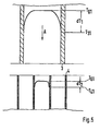
- FIG. 5 shows the effect of these measures on the basis of a temperature distribution in a section through the first two carrier disks 3 and 4: on the flow path in the direction of flow A through the first carrier disk 3, the temperature between the exhaust gas flow T G and the matrix temperature is established T 3 is a large temperature difference dT 1 .
- the first carrier disk 3 is made, for example, of a metallic material and has large cells, ie a low cell density.
- a lesser temperature difference dT 2 arises between the temperature of the exhaust gas flow T G and the matrix temperature T 4 .
- the difference between the first temperature difference dT 1 and the second temperature difference dT 2 may be more than 50 ° C.
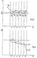
- Fig. 3 illustrates the course of the exhaust gas and Matrixtemperaturen with increasing heating at a time after reaching the desorption temperature td and the light-off temperature tl.
- the desorption temperature td is reached in the area of the first adsorptively coated carrier disk 3 and the light-off temperature t1 in the subsequent catalytically active carrier disk 4.
- the temperature rises disproportionately to the matrix temperature T 42 in the region of the catalytically active carrier disk 4.
- the higher exit temperature at the catalytically active carrier disk 4 causes a corresponding increase in temperature T 52 in the nachfogenden adsorbent carrier disk 5 to a temperature above the desorption temperature td.
- FIG. 4 illustrates the course of the concentration of HC parallel to the temperature profiles shown in FIG. 3.
- HC is adsorbed in the adsorptive carrier disks 3, 5 and 7.
- the HC concentration decreases steadily.
- the following, adsorptively coated support disk 5 also desorbs HC, since its temperature T 52 is above the desorption temperature td. As a result, the HC concentration in the course of this carrier disk 5 increases.
- the following catalytically active carrier disc 6 reduces the increased concentration, in turn, due to the catalytic reaction which acts here.
- Auslegungsgeiques succeeds in the last catalytically active carrier disk 8 a substantially complete conversion of HC, while the first two catalytically active carrier disks 4 and 6 are designed so that a conversion of HC takes place only up to about the HC concentration, the previously present in the entry of the subsequent adsorbent carrier disk 5 and 7 respectively was. By this measure it is prevented that by a too low HC concentration in the inlet the second and third adsorbent carrier disc 5 and 7 then desorption already is initiated when the temperature in the respective subsequent catalytic Carrier disk for a catalytic conversion would not be enough.
Landscapes
- Engineering & Computer Science (AREA)
- Chemical & Material Sciences (AREA)
- Combustion & Propulsion (AREA)
- Chemical Kinetics & Catalysis (AREA)
- General Engineering & Computer Science (AREA)
- Mechanical Engineering (AREA)
- Health & Medical Sciences (AREA)
- General Chemical & Material Sciences (AREA)
- Oil, Petroleum & Natural Gas (AREA)
- Analytical Chemistry (AREA)
- Environmental & Geological Engineering (AREA)
- Biomedical Technology (AREA)
- Materials Engineering (AREA)
- Exhaust Gas After Treatment (AREA)
Description
- Fig. 1
- einen Schnitt durch eine Adsorber-Katalysator-Kombination,
- Fig. 2
- ein Temperturschaubild zur Darstellung der Temperaturverteilung innerhalb der Adsorber-Katalysator-Kombination vor Erreichen der Desorptions-Temperatur und der Light-Off-Temperatur kurz nach dem Kaltstart einer Brennkraftmaschine,
- Fig. 3
- ein Temperturschaubild zur Darstellung der zeitlichen Entwicklung der Temperaturverteilung innerhalb der Adsorber-Katalysator-Kombination nach Erreichen der Desorptions-Temperatur und der Light-Off-Temperatur nach dem Kaltstart einer Brennkraftmaschine und
- Fig. 4
- ein Schaubild zur Darstellung der zeitlichen Entwicklung der Konzentration von HC innerhalb der Adsorber-Katalysator-Kombination nach dem Kaltstart einer Brennkraftmaschine.
Claims (8)
- Adsorber-Katalysator-Kombination für Brennkraftmaschinen, wobei innerhalb der Adsorber-Katalysator-Kombination (1) bezogen auf einen Abgasstrom (A) hintereinanderliegend zwei oder mehr Zonen (3 bis 8) von abwechselnd adsorbierend und katalytisch wirkendem Material vorgesehen sind, daß die adsorbierend wirkenden Zonen (3, 5, 7) thermodynamisch so ausgelegt sind, daß sie einen geringeren Wärmeübergang und/oder eine höhere Wärmekapazität aufweisen als die katalytisch wirkenden Zone (4, 6, 8), dadurch gekennzeichnet, daß die adsorbierend wirkenden Zonen (3, 5, 7) eine geringere Zelldichte und eine glatte Oberfläche aufweisen und die katalytisch wirkenden Zonen (4, 6, 8) eine hohe Zelldichte und eine rauhe Oberfläche aufweisen und daß eine Temperaturleitfähigkeit innerhalb der adsorbierend wirkenden Zone (3, 5, 7) größer gewählt ist als innerhalb der katalytisch wirkenden Zone (4, 6, 8).
- Adsorber-Katalysator-Kombination nach Anspruch 1 oder 2, dadurch gekennzeichnet, daß die Tiefe der Zonen (3 bis 8) so gewählt ist, daß eine Matrix-Temperatur (Ti) am Eintritt einer katalytisch wirkenden Zone (4, 6, 8) schon oberhalb der Light-off-Temperatur liegt, wenn die Matrix-Temperatur am Austritt der vorgeschalteten adsorbierend wirkenden Zone (3, 5, 7) noch unterhalb der Desorptionstemperatur liegt.
- Adsorber-Katalysator-Kombination nach einem der vorstehenden Ansprüche, dadurch gekennzeichnet, daß als letzte Zone eine katalytisch wirkende Zone (8) vorgesehen ist.
- Adsorber-Katalysator-Kombination nach einem der vorstehenden Ansprüche, dadurch gekennzeichnet, daß die adsorbierend wirkenden Zonen (3, 5, 7) zusätzlich in geeigneter Weise katalytisch wirksam beschichtet sind.
- Adsorber-Katalysator-Kombination nach einem der vorstehenden Ansprüche, dadurch gekennzeichnet, daß die Zonen (3 bis 8) in Form von scheibenförmigen Trägermaterial ausgebildet sind, die mit einer adsorbierend bzw. katalytisch wirkenden Beschichtung versehen sind und die Scheiben (3 bis 8) hinsichtlich ihrer äußeren Durchmesser gleich sind.
- Adsorber-Katalysator-Kombination nach Anspruch 8, dadurch gekennzeichnet, daß die Scheiben (3 bis 8) in Form eines Stapels angeordnet sind.
- Adsorber-Katalysator-Kombination nach einem der vorstehenden Ansprüche, dadurch gekennzeichnet, daß die adsorbierend wirkenden Zonen (3, 5, 7) eine höhere Wandstärke aufweisen als die katalytisch wirkenden Zone (4, 6, 8).
- Adsorber-Katalysator-Kombination nach einem der vorstehenden Ansprüche, dadurch gekennzeichnet, daß die Zonen (3 bis 8) hinsichtlich der Auswahl von Werkstoff und geometrischen Abmessungen thermodynamisch so ausgelegt sind, daß ihre Aufheizzeit minimiert ist
Applications Claiming Priority (2)
| Application Number | Priority Date | Filing Date | Title |
|---|---|---|---|
| DE19712087A DE19712087C2 (de) | 1997-03-22 | 1997-03-22 | Adsorber-Katalysator-Kombination für Brennkraftmaschinen |
| DE19712087 | 1997-03-22 |
Publications (2)
| Publication Number | Publication Date |
|---|---|
| EP0866218A1 EP0866218A1 (de) | 1998-09-23 |
| EP0866218B1 true EP0866218B1 (de) | 2003-07-23 |
Family
ID=7824299
Family Applications (1)
| Application Number | Title | Priority Date | Filing Date |
|---|---|---|---|
| EP98102587A Expired - Lifetime EP0866218B1 (de) | 1997-03-22 | 1998-02-14 | Adsorber-Katalysator- Kombination für Brennkraftmaschinen |
Country Status (4)
| Country | Link |
|---|---|
| US (1) | US6113864A (de) |
| EP (1) | EP0866218B1 (de) |
| JP (1) | JPH10266829A (de) |
| DE (2) | DE19712087C2 (de) |
Families Citing this family (15)
| Publication number | Priority date | Publication date | Assignee | Title |
|---|---|---|---|---|
| US6447735B1 (en) * | 1998-04-30 | 2002-09-10 | Nissan Motor Co., Ltd. | Exhaust purifier and manufacturing method of same |
| US6221327B1 (en) | 1998-05-15 | 2001-04-24 | Rohm And Haas Company | Catalyst system using flow-through radiation shielding and a process for producing hydrogen cyanide using the same |
| JP3402200B2 (ja) * | 1998-06-01 | 2003-04-28 | 日産自動車株式会社 | 内燃機関の排気浄化装置 |
| WO2001012961A1 (en) * | 1999-08-13 | 2001-02-22 | Corning Incorporated | Compact catalyst/adsorber for exhaust gas treatment |
| DE10036942B4 (de) * | 2000-07-28 | 2009-12-24 | Volkswagen Ag | Verfahren zur Bestimmung der Temperaturverteilung eines NOx-Katalysators |
| DE10051562A1 (de) * | 2000-10-18 | 2002-04-25 | Emitec Emissionstechnologie | Beheizbarer Wabenkörper mit zwei verschiedenen Beschichtungen |
| JP4863596B2 (ja) * | 2001-06-18 | 2012-01-25 | 日産自動車株式会社 | 排気ガス浄化システム |
| JP2003201832A (ja) | 2001-10-25 | 2003-07-18 | Nissan Motor Co Ltd | 排ガス浄化触媒システム |
| US6532659B1 (en) * | 2001-11-29 | 2003-03-18 | Delphi Technologies, Inc. | Method of forming a gas treatment device using a stuffing cone apparatus |
| US20030202918A1 (en) * | 2002-04-24 | 2003-10-30 | Nissan Motor Co., Ltd. | Exhaust gas purification device |
| US9284226B2 (en) * | 2010-12-08 | 2016-03-15 | Minova International Limited | Cementitious compositions |
| US9541043B2 (en) * | 2015-03-31 | 2017-01-10 | Mann+Hummel Gmbh | Hydrocarbon adsorber and related manufacturing methods |
| US9897049B2 (en) * | 2015-03-31 | 2018-02-20 | Mann+Hummel Gmbh | Air intake tract with a hydrocarbon adsorber and related manufacturing methods |
| JP6575295B2 (ja) * | 2015-10-23 | 2019-09-18 | 日産自動車株式会社 | 燃料電池電極用触媒インクの測定装置、および燃料電池電極用触媒インクの測定方法 |
| WO2020064579A1 (de) * | 2018-09-27 | 2020-04-02 | Vitesco Technologies GmbH | Vorrichtung zur abgasnachbehandlung |
Citations (1)
| Publication number | Priority date | Publication date | Assignee | Title |
|---|---|---|---|---|
| EP0908225A2 (de) * | 1995-06-23 | 1999-04-14 | Ngk Insulators, Ltd. | Verfahren und Vorrichtung zur Abgasreinigung |
Family Cites Families (7)
| Publication number | Priority date | Publication date | Assignee | Title |
|---|---|---|---|---|
| JP3046051B2 (ja) * | 1990-09-28 | 2000-05-29 | マツダ株式会社 | エンジンの排気ガス浄化装置 |
| US5296198A (en) * | 1990-11-09 | 1994-03-22 | Ngk Insulators, Ltd. | Heater and catalytic converter |
| JPH06185342A (ja) * | 1992-12-21 | 1994-07-05 | Mazda Motor Corp | 排気ガス浄化装置 |
| JPH06272542A (ja) * | 1993-03-17 | 1994-09-27 | Hitachi Ltd | 内燃機関の排気浄化制御装置及び制御方法 |
| DE4314043A1 (de) * | 1993-04-29 | 1994-11-03 | Porsche Ag | Abgasreinigungsvorrichtung für eine Brennkraftmaschine |
| JP3526084B2 (ja) * | 1993-12-28 | 2004-05-10 | 日本碍子株式会社 | 排ガス浄化用吸着・触媒体、吸着体、排ガス浄化システム及び排ガス浄化方法 |
| DE19543219C1 (de) * | 1995-11-20 | 1996-12-05 | Daimler Benz Ag | Verfahren zum Betreiben eines Dieselmotors |
-
1997
- 1997-03-22 DE DE19712087A patent/DE19712087C2/de not_active Expired - Fee Related
-
1998
- 1998-02-14 EP EP98102587A patent/EP0866218B1/de not_active Expired - Lifetime
- 1998-02-14 DE DE59809043T patent/DE59809043D1/de not_active Expired - Fee Related
- 1998-03-19 JP JP10069689A patent/JPH10266829A/ja active Pending
- 1998-03-23 US US09/045,699 patent/US6113864A/en not_active Expired - Fee Related
Patent Citations (1)
| Publication number | Priority date | Publication date | Assignee | Title |
|---|---|---|---|---|
| EP0908225A2 (de) * | 1995-06-23 | 1999-04-14 | Ngk Insulators, Ltd. | Verfahren und Vorrichtung zur Abgasreinigung |
Also Published As
| Publication number | Publication date |
|---|---|
| US6113864A (en) | 2000-09-05 |
| DE19712087C2 (de) | 1999-07-22 |
| JPH10266829A (ja) | 1998-10-06 |
| DE19712087A1 (de) | 1998-09-24 |
| DE59809043D1 (de) | 2003-08-28 |
| EP0866218A1 (de) | 1998-09-23 |
Similar Documents
| Publication | Publication Date | Title |
|---|---|---|
| EP0866218B1 (de) | Adsorber-Katalysator- Kombination für Brennkraftmaschinen | |
| DE19539728B4 (de) | Monolithischer Zeolit/Katalysator-Wandflußadsorber | |
| EP0892887B1 (de) | Hitzebeständiger und regenerierbarer filterkörper mit strömungswegen | |
| DE60306305T2 (de) | Bimodales Harnstoff-SCR-Katalysatorsystem zur verbesserten NOx Umwandlung und erhöhter Lebensdauer | |
| DE69417861T2 (de) | Honigwabenheizgerät | |
| EP1078150B1 (de) | Katalytischer konverter, insbesondere für einen dieselmotor oder einen magermotor | |
| EP0505832A1 (de) | Filter- oder Katalysatorkörper | |
| DE4005189A1 (de) | Abgasreinigungsvorrichtung fuer einen dieselmotor | |
| EP1328711B1 (de) | Beheizbarer wabenkörper mit zwei verschiedenen beschichtungen | |
| DE19701169A1 (de) | Katalytischer Konverter | |
| EP2823163B1 (de) | Abgasreinigungsvorrichtung | |
| DE102019101679A1 (de) | Abgasheizelement | |
| DE112013002164T5 (de) | Axial geschnittene keramische Wabeneinheiten | |
| EP1522686B1 (de) | Abgasreinigungsanordnung | |
| EP1527262B1 (de) | Abgasfilter und verfahren zum reinigen eines abgases | |
| EP0056584B1 (de) | Bifunktionaler Filter zur Behandlung von Abgasen | |
| EP2166203B1 (de) | Vorrichtung zur Reinigung eines Abgasstroms einer Brennkraftmaschine eines Kraftfahrzeuges, insbesondere eines Nutzfahrzeuges | |
| EP3879084B1 (de) | Abgasbehandlungssystem für eine abgasanlage einer brennkraftmaschine und verfahren zum betreiben eines derartigen abgasbehandlungssystems | |
| DE102007056213A1 (de) | Verfahren zur Herstellung eines von Abgas durchströmbaren Formkörpers sowie Abgasanlage einer Brennkraftmaschine | |
| DE69414817T2 (de) | Honigwabenheizgerät | |
| DE2826843A1 (de) | Vorrichtung zur behandlung von fluiden, insbesondere zur katalytischen behandlung von fluiden | |
| DE69313695T2 (de) | Verfahren zur katalytischen Reinigung der Abgase einer Brennkraftmaschine und Abgasvorrichtung | |
| DE4431134C2 (de) | Vorrichtung zur Verbesserung der Temperaturbeständigkeit von Katalysatoren für Verbrennungskraftmaschinen | |
| DE102007036254A1 (de) | Abgasanlage einer Brennkraftmaschine | |
| EP1431528B1 (de) | Abgasreinigungsanordnung |
Legal Events
| Date | Code | Title | Description |
|---|---|---|---|
| PUAI | Public reference made under article 153(3) epc to a published international application that has entered the european phase |
Free format text: ORIGINAL CODE: 0009012 |
|
| AK | Designated contracting states |
Kind code of ref document: A1 Designated state(s): DE FR GB IT |
|
| AX | Request for extension of the european patent |
Free format text: AL;LT;LV;MK;RO;SI |
|
| RAP1 | Party data changed (applicant data changed or rights of an application transferred) |
Owner name: VOLKSWAGEN AKTIENGESELLSCHAFT Owner name: BAYERISCHE MOTOREN WERKE AKTIENGESELLSCHAFT Owner name: DAIMLERCHRYSLER AG Owner name: DR.ING.H.C. F. PORSCHE AKTIENGESELLSCHAFT |
|
| 17P | Request for examination filed |
Effective date: 19990226 |
|
| AKX | Designation fees paid |
Free format text: DE FR GB IT |
|
| RBV | Designated contracting states (corrected) |
Designated state(s): DE FR GB IT |
|
| 17Q | First examination report despatched |
Effective date: 20010425 |
|
| GRAH | Despatch of communication of intention to grant a patent |
Free format text: ORIGINAL CODE: EPIDOS IGRA |
|
| GRAH | Despatch of communication of intention to grant a patent |
Free format text: ORIGINAL CODE: EPIDOS IGRA |
|
| GRAA | (expected) grant |
Free format text: ORIGINAL CODE: 0009210 |
|
| AK | Designated contracting states |
Designated state(s): DE FR GB IT |
|
| REG | Reference to a national code |
Ref country code: GB Ref legal event code: FG4D Free format text: NOT ENGLISH |
|
| GBT | Gb: translation of ep patent filed (gb section 77(6)(a)/1977) |
Effective date: 20030728 |
|
| REF | Corresponds to: |
Ref document number: 59809043 Country of ref document: DE Date of ref document: 20030828 Kind code of ref document: P |
|
| ET | Fr: translation filed | ||
| PLBE | No opposition filed within time limit |
Free format text: ORIGINAL CODE: 0009261 |
|
| STAA | Information on the status of an ep patent application or granted ep patent |
Free format text: STATUS: NO OPPOSITION FILED WITHIN TIME LIMIT |
|
| 26N | No opposition filed |
Effective date: 20040426 |
|
| PGFP | Annual fee paid to national office [announced via postgrant information from national office to epo] |
Ref country code: GB Payment date: 20050209 Year of fee payment: 8 |
|
| PGFP | Annual fee paid to national office [announced via postgrant information from national office to epo] |
Ref country code: DE Payment date: 20050214 Year of fee payment: 8 |
|
| PGFP | Annual fee paid to national office [announced via postgrant information from national office to epo] |
Ref country code: FR Payment date: 20050225 Year of fee payment: 8 |
|
| PG25 | Lapsed in a contracting state [announced via postgrant information from national office to epo] |
Ref country code: GB Free format text: LAPSE BECAUSE OF NON-PAYMENT OF DUE FEES Effective date: 20060214 |
|
| PGFP | Annual fee paid to national office [announced via postgrant information from national office to epo] |
Ref country code: IT Payment date: 20060228 Year of fee payment: 9 |
|
| PG25 | Lapsed in a contracting state [announced via postgrant information from national office to epo] |
Ref country code: DE Free format text: LAPSE BECAUSE OF NON-PAYMENT OF DUE FEES Effective date: 20060901 |
|
| GBPC | Gb: european patent ceased through non-payment of renewal fee |
Effective date: 20060214 |
|
| REG | Reference to a national code |
Ref country code: FR Ref legal event code: ST Effective date: 20061031 |
|
| PG25 | Lapsed in a contracting state [announced via postgrant information from national office to epo] |
Ref country code: FR Free format text: LAPSE BECAUSE OF NON-PAYMENT OF DUE FEES Effective date: 20060228 |
|
| PG25 | Lapsed in a contracting state [announced via postgrant information from national office to epo] |
Ref country code: IT Free format text: LAPSE BECAUSE OF NON-PAYMENT OF DUE FEES Effective date: 20070214 |