EP0866224A1 - Pompe à engrenages pour le déplacement de fluides - Google Patents
Pompe à engrenages pour le déplacement de fluides Download PDFInfo
- Publication number
- EP0866224A1 EP0866224A1 EP98103651A EP98103651A EP0866224A1 EP 0866224 A1 EP0866224 A1 EP 0866224A1 EP 98103651 A EP98103651 A EP 98103651A EP 98103651 A EP98103651 A EP 98103651A EP 0866224 A1 EP0866224 A1 EP 0866224A1
- Authority
- EP
- European Patent Office
- Prior art keywords
- working chamber
- gear
- gear pump
- pump according
- parts
- Prior art date
- Legal status (The legal status is an assumption and is not a legal conclusion. Google has not performed a legal analysis and makes no representation as to the accuracy of the status listed.)
- Granted
Links
- 239000012530 fluid Substances 0.000 title claims description 22
- OKTJSMMVPCPJKN-UHFFFAOYSA-N Carbon Chemical compound [C] OKTJSMMVPCPJKN-UHFFFAOYSA-N 0.000 claims abstract description 44
- 229910052799 carbon Inorganic materials 0.000 claims abstract description 29
- 239000000463 material Substances 0.000 claims abstract description 27
- 239000000945 filler Substances 0.000 claims abstract description 19
- 239000000571 coke Substances 0.000 claims abstract description 10
- 229910052751 metal Inorganic materials 0.000 claims abstract description 9
- 239000002184 metal Substances 0.000 claims abstract description 9
- 229910002804 graphite Inorganic materials 0.000 claims abstract description 7
- 239000010439 graphite Substances 0.000 claims abstract description 7
- 239000011159 matrix material Substances 0.000 claims abstract description 6
- 239000011301 petroleum pitch Substances 0.000 claims abstract description 6
- 239000011148 porous material Substances 0.000 claims abstract description 6
- 229920001187 thermosetting polymer Polymers 0.000 claims abstract description 6
- 229910052500 inorganic mineral Inorganic materials 0.000 claims abstract description 5
- 239000011707 mineral Substances 0.000 claims abstract description 5
- 239000007849 furan resin Substances 0.000 claims abstract description 4
- 239000005011 phenolic resin Substances 0.000 claims abstract description 4
- 229920001225 polyester resin Polymers 0.000 claims abstract description 4
- 239000004645 polyester resin Substances 0.000 claims abstract description 4
- 239000004952 Polyamide Substances 0.000 claims abstract description 3
- 239000000919 ceramic Substances 0.000 claims abstract description 3
- 229920001568 phenolic resin Polymers 0.000 claims abstract description 3
- 229920002647 polyamide Polymers 0.000 claims abstract description 3
- 229910000831 Steel Inorganic materials 0.000 claims abstract 2
- HDNHWROHHSBKJG-UHFFFAOYSA-N formaldehyde;furan-2-ylmethanol Chemical compound O=C.OCC1=CC=CO1 HDNHWROHHSBKJG-UHFFFAOYSA-N 0.000 claims abstract 2
- 239000010959 steel Substances 0.000 claims abstract 2
- 239000011230 binding agent Substances 0.000 claims description 18
- 239000000203 mixture Substances 0.000 claims description 15
- 239000000126 substance Substances 0.000 claims description 8
- 239000003795 chemical substances by application Substances 0.000 claims description 6
- 239000011294 coal tar pitch Substances 0.000 claims description 6
- 230000000295 complement effect Effects 0.000 claims description 6
- 238000007789 sealing Methods 0.000 claims description 6
- VYPSYNLAJGMNEJ-UHFFFAOYSA-N Silicium dioxide Chemical compound O=[Si]=O VYPSYNLAJGMNEJ-UHFFFAOYSA-N 0.000 claims description 5
- 238000004939 coking Methods 0.000 claims description 4
- HBMJWWWQQXIZIP-UHFFFAOYSA-N silicon carbide Chemical compound [Si+]#[C-] HBMJWWWQQXIZIP-UHFFFAOYSA-N 0.000 claims description 4
- 229910010271 silicon carbide Inorganic materials 0.000 claims description 4
- 229920003002 synthetic resin Polymers 0.000 claims description 4
- 239000000057 synthetic resin Substances 0.000 claims description 4
- 239000000470 constituent Substances 0.000 claims description 3
- 239000010433 feldspar Substances 0.000 claims description 3
- 229910021382 natural graphite Inorganic materials 0.000 claims description 3
- 235000012239 silicon dioxide Nutrition 0.000 claims description 3
- 239000010935 stainless steel Substances 0.000 claims description 3
- 229910001220 stainless steel Inorganic materials 0.000 claims description 3
- 229910052580 B4C Inorganic materials 0.000 claims description 2
- 229910052581 Si3N4 Inorganic materials 0.000 claims description 2
- INAHAJYZKVIDIZ-UHFFFAOYSA-N boron carbide Chemical compound B12B3B4C32B41 INAHAJYZKVIDIZ-UHFFFAOYSA-N 0.000 claims description 2
- 229930195733 hydrocarbon Natural products 0.000 claims description 2
- 150000002430 hydrocarbons Chemical class 0.000 claims description 2
- 150000001247 metal acetylides Chemical class 0.000 claims description 2
- 229910001092 metal group alloy Inorganic materials 0.000 claims description 2
- 150000004767 nitrides Chemical class 0.000 claims description 2
- TWNQGVIAIRXVLR-UHFFFAOYSA-N oxo(oxoalumanyloxy)alumane Chemical compound O=[Al]O[Al]=O TWNQGVIAIRXVLR-UHFFFAOYSA-N 0.000 claims description 2
- 150000004760 silicates Chemical class 0.000 claims description 2
- 239000000377 silicon dioxide Substances 0.000 claims description 2
- HQVNEWCFYHHQES-UHFFFAOYSA-N silicon nitride Chemical compound N12[Si]34N5[Si]62N3[Si]51N64 HQVNEWCFYHHQES-UHFFFAOYSA-N 0.000 claims description 2
- 239000012815 thermoplastic material Substances 0.000 claims 2
- -1 ferrous metals Chemical class 0.000 claims 1
- 150000002739 metals Chemical class 0.000 claims 1
- 239000000843 powder Substances 0.000 abstract description 9
- 229920001169 thermoplastic Polymers 0.000 abstract description 3
- CWYNVVGOOAEACU-UHFFFAOYSA-N Fe2+ Chemical compound [Fe+2] CWYNVVGOOAEACU-UHFFFAOYSA-N 0.000 abstract description 2
- 239000013032 Hydrocarbon resin Substances 0.000 abstract description 2
- 229910045601 alloy Inorganic materials 0.000 abstract description 2
- 239000000956 alloy Substances 0.000 abstract description 2
- 239000011341 hard coal tar pitch Substances 0.000 abstract description 2
- 229920006270 hydrocarbon resin Polymers 0.000 abstract description 2
- 239000004416 thermosoftening plastic Substances 0.000 abstract description 2
- 229920002994 synthetic fiber Polymers 0.000 abstract 1
- 239000003575 carbonaceous material Substances 0.000 description 26
- 239000007788 liquid Substances 0.000 description 10
- 238000000034 method Methods 0.000 description 8
- 210000003734 kidney Anatomy 0.000 description 6
- 230000001050 lubricating effect Effects 0.000 description 6
- 238000004519 manufacturing process Methods 0.000 description 6
- 238000002156 mixing Methods 0.000 description 6
- YLQBMQCUIZJEEH-UHFFFAOYSA-N Furan Chemical compound C=1C=COC=1 YLQBMQCUIZJEEH-UHFFFAOYSA-N 0.000 description 4
- 235000013339 cereals Nutrition 0.000 description 4
- 230000007797 corrosion Effects 0.000 description 4
- 238000005260 corrosion Methods 0.000 description 4
- 238000000465 moulding Methods 0.000 description 4
- 239000011295 pitch Substances 0.000 description 4
- 238000003763 carbonization Methods 0.000 description 3
- 238000005516 engineering process Methods 0.000 description 3
- 230000003628 erosive effect Effects 0.000 description 3
- 238000005470 impregnation Methods 0.000 description 3
- 230000001737 promoting effect Effects 0.000 description 3
- 230000001681 protective effect Effects 0.000 description 3
- XLYOFNOQVPJJNP-UHFFFAOYSA-N water Substances O XLYOFNOQVPJJNP-UHFFFAOYSA-N 0.000 description 3
- 229910000881 Cu alloy Inorganic materials 0.000 description 2
- 238000005299 abrasion Methods 0.000 description 2
- 238000010000 carbonizing Methods 0.000 description 2
- 238000005229 chemical vapour deposition Methods 0.000 description 2
- 230000007717 exclusion Effects 0.000 description 2
- 238000010304 firing Methods 0.000 description 2
- 238000005087 graphitization Methods 0.000 description 2
- 230000001590 oxidative effect Effects 0.000 description 2
- ISWSIDIOOBJBQZ-UHFFFAOYSA-N phenol group Chemical group C1(=CC=CC=C1)O ISWSIDIOOBJBQZ-UHFFFAOYSA-N 0.000 description 2
- 238000003825 pressing Methods 0.000 description 2
- 229920005989 resin Polymers 0.000 description 2
- 239000011347 resin Substances 0.000 description 2
- 229920003987 resole Polymers 0.000 description 2
- 239000007787 solid Substances 0.000 description 2
- 238000003860 storage Methods 0.000 description 2
- 230000003319 supportive effect Effects 0.000 description 2
- RYGMFSIKBFXOCR-UHFFFAOYSA-N Copper Chemical compound [Cu] RYGMFSIKBFXOCR-UHFFFAOYSA-N 0.000 description 1
- 239000004642 Polyimide Substances 0.000 description 1
- 229910001245 Sb alloy Inorganic materials 0.000 description 1
- 229910052787 antimony Inorganic materials 0.000 description 1
- 239000002140 antimony alloy Substances 0.000 description 1
- WATWJIUSRGPENY-UHFFFAOYSA-N antimony atom Chemical compound [Sb] WATWJIUSRGPENY-UHFFFAOYSA-N 0.000 description 1
- 230000005540 biological transmission Effects 0.000 description 1
- 238000009835 boiling Methods 0.000 description 1
- 238000006243 chemical reaction Methods 0.000 description 1
- 238000005253 cladding Methods 0.000 description 1
- 230000006835 compression Effects 0.000 description 1
- 238000007906 compression Methods 0.000 description 1
- 239000004035 construction material Substances 0.000 description 1
- 238000001816 cooling Methods 0.000 description 1
- 239000010949 copper Substances 0.000 description 1
- 230000001419 dependent effect Effects 0.000 description 1
- 239000002283 diesel fuel Substances 0.000 description 1
- 238000007599 discharging Methods 0.000 description 1
- 230000000694 effects Effects 0.000 description 1
- 239000000835 fiber Substances 0.000 description 1
- 239000012765 fibrous filler Substances 0.000 description 1
- 238000011049 filling Methods 0.000 description 1
- 239000010419 fine particle Substances 0.000 description 1
- 235000013312 flour Nutrition 0.000 description 1
- 238000010438 heat treatment Methods 0.000 description 1
- 239000003350 kerosene Substances 0.000 description 1
- 229910001338 liquidmetal Inorganic materials 0.000 description 1
- 238000005461 lubrication Methods 0.000 description 1
- 238000011089 mechanical engineering Methods 0.000 description 1
- 239000007769 metal material Substances 0.000 description 1
- 238000010310 metallurgical process Methods 0.000 description 1
- 239000003921 oil Substances 0.000 description 1
- 239000004033 plastic Substances 0.000 description 1
- 229920003023 plastic Polymers 0.000 description 1
- 229920006122 polyamide resin Polymers 0.000 description 1
- 229920001721 polyimide Polymers 0.000 description 1
- 229910052573 porcelain Inorganic materials 0.000 description 1
- 239000002243 precursor Substances 0.000 description 1
- 238000002360 preparation method Methods 0.000 description 1
- 238000005086 pumping Methods 0.000 description 1
- 238000000197 pyrolysis Methods 0.000 description 1
- 239000010453 quartz Substances 0.000 description 1
- 230000035939 shock Effects 0.000 description 1
- 238000005979 thermal decomposition reaction Methods 0.000 description 1
- 229920005992 thermoplastic resin Polymers 0.000 description 1
Images


Classifications
-
- F—MECHANICAL ENGINEERING; LIGHTING; HEATING; WEAPONS; BLASTING
- F01—MACHINES OR ENGINES IN GENERAL; ENGINE PLANTS IN GENERAL; STEAM ENGINES
- F01C—ROTARY-PISTON OR OSCILLATING-PISTON MACHINES OR ENGINES
- F01C21/00—Component parts, details or accessories not provided for in groups F01C1/00 - F01C20/00
- F01C21/10—Outer members for co-operation with rotary pistons; Casings
- F01C21/104—Stators; Members defining the outer boundaries of the working chamber
-
- F—MECHANICAL ENGINEERING; LIGHTING; HEATING; WEAPONS; BLASTING
- F04—POSITIVE - DISPLACEMENT MACHINES FOR LIQUIDS; PUMPS FOR LIQUIDS OR ELASTIC FLUIDS
- F04C—ROTARY-PISTON, OR OSCILLATING-PISTON, POSITIVE-DISPLACEMENT MACHINES FOR LIQUIDS; ROTARY-PISTON, OR OSCILLATING-PISTON, POSITIVE-DISPLACEMENT PUMPS
- F04C2/00—Rotary-piston machines or pumps
- F04C2/08—Rotary-piston machines or pumps of intermeshing-engagement type, i.e. with engagement of co-operating members similar to that of toothed gearing
- F04C2/082—Details specially related to intermeshing engagement type machines or pumps
-
- F—MECHANICAL ENGINEERING; LIGHTING; HEATING; WEAPONS; BLASTING
- F04—POSITIVE - DISPLACEMENT MACHINES FOR LIQUIDS; PUMPS FOR LIQUIDS OR ELASTIC FLUIDS
- F04C—ROTARY-PISTON, OR OSCILLATING-PISTON, POSITIVE-DISPLACEMENT MACHINES FOR LIQUIDS; ROTARY-PISTON, OR OSCILLATING-PISTON, POSITIVE-DISPLACEMENT PUMPS
- F04C2/00—Rotary-piston machines or pumps
- F04C2/08—Rotary-piston machines or pumps of intermeshing-engagement type, i.e. with engagement of co-operating members similar to that of toothed gearing
- F04C2/10—Rotary-piston machines or pumps of intermeshing-engagement type, i.e. with engagement of co-operating members similar to that of toothed gearing of internal-axis type with the outer member having more teeth or tooth-equivalents, e.g. rollers, than the inner member
- F04C2/102—Rotary-piston machines or pumps of intermeshing-engagement type, i.e. with engagement of co-operating members similar to that of toothed gearing of internal-axis type with the outer member having more teeth or tooth-equivalents, e.g. rollers, than the inner member the two members rotating simultaneously around their respective axes
-
- F—MECHANICAL ENGINEERING; LIGHTING; HEATING; WEAPONS; BLASTING
- F04—POSITIVE - DISPLACEMENT MACHINES FOR LIQUIDS; PUMPS FOR LIQUIDS OR ELASTIC FLUIDS
- F04C—ROTARY-PISTON, OR OSCILLATING-PISTON, POSITIVE-DISPLACEMENT MACHINES FOR LIQUIDS; ROTARY-PISTON, OR OSCILLATING-PISTON, POSITIVE-DISPLACEMENT PUMPS
- F04C2/00—Rotary-piston machines or pumps
- F04C2/08—Rotary-piston machines or pumps of intermeshing-engagement type, i.e. with engagement of co-operating members similar to that of toothed gearing
- F04C2/12—Rotary-piston machines or pumps of intermeshing-engagement type, i.e. with engagement of co-operating members similar to that of toothed gearing of other than internal-axis type
- F04C2/14—Rotary-piston machines or pumps of intermeshing-engagement type, i.e. with engagement of co-operating members similar to that of toothed gearing of other than internal-axis type with toothed rotary pistons
- F04C2/18—Rotary-piston machines or pumps of intermeshing-engagement type, i.e. with engagement of co-operating members similar to that of toothed gearing of other than internal-axis type with toothed rotary pistons with similar tooth forms
-
- F—MECHANICAL ENGINEERING; LIGHTING; HEATING; WEAPONS; BLASTING
- F04—POSITIVE - DISPLACEMENT MACHINES FOR LIQUIDS; PUMPS FOR LIQUIDS OR ELASTIC FLUIDS
- F04C—ROTARY-PISTON, OR OSCILLATING-PISTON, POSITIVE-DISPLACEMENT MACHINES FOR LIQUIDS; ROTARY-PISTON, OR OSCILLATING-PISTON, POSITIVE-DISPLACEMENT PUMPS
- F04C2240/00—Components
- F04C2240/80—Other components
- F04C2240/802—Liners
-
- F—MECHANICAL ENGINEERING; LIGHTING; HEATING; WEAPONS; BLASTING
- F05—INDEXING SCHEMES RELATING TO ENGINES OR PUMPS IN VARIOUS SUBCLASSES OF CLASSES F01-F04
- F05C—INDEXING SCHEME RELATING TO MATERIALS, MATERIAL PROPERTIES OR MATERIAL CHARACTERISTICS FOR MACHINES, ENGINES OR PUMPS OTHER THAN NON-POSITIVE-DISPLACEMENT MACHINES OR ENGINES
- F05C2203/00—Non-metallic inorganic materials
- F05C2203/08—Ceramics; Oxides
- F05C2203/0865—Oxide ceramics
- F05C2203/0882—Carbon, e.g. graphite
Definitions
- the invention relates to a gear pump for conveying Fluids according to the preamble of claim 1.
- Gear pumps with internal teeth and those with external teeth are used to a considerable extent in technology hydraulic power transmission in the pressure range of approx. 10 to 250 bar used.
- Conveying lubricating fluids such as oils of all kinds Type or of diesel fuel.
- Conveying lubricating fluids such as oils of all kinds Type or of diesel fuel.
- poorly or non-lubricating fluids such as Water, low boiling hydrocarbons, in particular Petrol or kerosene, or from solutions or mixtures existing drinks occur when using gear pumps even at low fluid pressures on the outlet side problems from about 2 to 10 bar after a short time.
- the Friction becomes too high and the pumps fall due to erosion and / or corrosion. Problems of this kind also result in Operating areas in which with a temporary dry run or worked with temporarily interrupted lubricating films must be to the failure of the pumps.
- Parts made of carbon have long been used in mechanical engineering e.g. as slip rings, sealing rings, slide bearings, slide rings or slide gate (see e.g. Jörres, engineering materials I No. 11/12 (1989) and engineering materials 2, No. 1/2 (1990)).
- the use of such Parts made of carbon - the following should, if on corresponding differences in material qualities not specifically pointed out in the term Carbon also included graphite - not unproblematic as it is when using carbon parts always choosing one for the prevailing Suitable material pairing for operating conditions arrives.
- Gear pumps used for pumping fluids missing or insufficient lubricity are, because up to now corresponding attempts at Conveying such media with gear pumps early erosion and / or corrosion-related Failure of the pumps failed.
- the promotion of fluids of the above type with gear pumps is not technically manageable. It’s therefore a result of inventive rank, if only for promoting such bad or suitable for non-lubricating fluids in continuous operation Gear pumps are provided.
- An essential feature of the pumps is that they are the most promotional gears surrounding housing of the working chamber the pump made of a synthetically manufactured carbon material exists, which is fluid-tight.
- the pump made of a synthetically manufactured carbon material exists, which is fluid-tight.
- both gear wheels located in the delivery chamber axially on the surrounding them on both sides, from the Carbon material existing walls of the delivery chamber slidably mounted.
- the two sides of the working chamber also as bearing blocks trained for the axes of the gears, so that also the axes of the gears in suitably shaped Bearing bushes made of carbon are stored.
- the housing of the working chamber preferably consists of a carbon material with a matrix of a carbonized carbon which has not been heated to the graphitization temperature.
- This matrix is obtained by coking or carbonizing the binder of a precursor body containing coking materials for the production of the carbon material.
- the pre-product body is composed of the binder and certain fillers. When carbonizing this body, work must be carried out below a temperature at which graphitization processes occur. A final temperature of 900 to 1000 ° C. is preferably used. Coking or carbonization is carried out in the manner known to those skilled in the field of carbon technology with the exclusion of substances having an oxidizing effect.
- the binder used is either a coal tar pitch, a petroleum pitch or a mixture of one of the aforementioned types of pitch and a synthetic resin.
- care must be taken to ensure that after carbonization the binder has a coke yield of at least 50, preferably more than 60 and particularly preferably more than 65 percent by weight (determination according to DIN 51905).
- the binder is mixed with the filler.
- the binder can be mixed with the filler in both liquid and finely powdered form. Mixing in finely powdered form is used especially when processing pitches with high softening points. However, it is also possible to mix the binder in liquid form with the filler at temperatures above its softening point.
- carbon moldings can be pressed from mixtures produced by both mixing processes.
- the preferred procedure when working with pitches is the introduction and mixing in of the binder in powdered form and the subsequent pressing of shaped bodies from the filler powder / binder powder mixture obtained. If a mixture of a binder in liquid form with the filler has been chosen, it is advantageous to grind the binder-filler mixture obtained into a fine particle size before compression to form shaped bodies and then to compress this ground material into shaped bodies.
- the pressing is preferably carried out in die or isostatic presses. All of the so-called green moldings produced by one of the aforementioned processes are then fed to the carbonization process.
- the filler content in the preliminary product and in the carbon material consists of 35 to 97% by weight of graphite, 0 to 62% by weight of non-graphitized petroleum or hard coal tar pitch coke and 3 to 20% by weight of mineral, the tribological properties of the components influencing the material.
- the graphitic part of the filler can be natural graphite, kishgraphite, electrographite, ie graphite produced synthetically, electrothermally or also graphitized coke, or it can consist of a mixture of one or more of the aforementioned substances.
- the material in the graphitizing process which must also be carried out with the exclusion of oxidizing media, must be exposed to a temperature of at least 1800 ° C., preferably of more than 2400 ° C. to 3000 ° C.
- the second part of the filler consists of non-graphitized petroleum or coal tar pitch coke. These cokes already belong to the harder part of the carbon material which has less lubricity but which increases the resistance to abrasion.
- the third part of the filler is formed by hard materials, which preferably consist of or contain oxides, carbides, nitrides, borides or silicates.
- Silicon dioxide, silicon carbide, aluminum oxide, boron carbide, silicon nitride or feldspar are particularly preferably used.
- the purpose of these materials is to further increase the abrasion resistance of the carbon material and to keep the counter surfaces clean during operation by means of a slight sanding effect.
- each of the constituents that later form the filler is ground to a fineness of flour.
- the moldings produced are after firing the exit of pyrolysis products of the binder fraction porous.
- a liquid impregnating agent that either solidifies after impregnation, or is cured.
- Impregnation agents become thermosetting and thermoplastic Resins used.
- resins from the group of phenolic resins, in particular the Resol types, furan or polyester resins, perfluorinated Hydrocarbon resins or polyamide resins.
- synthetic resins as impregnating agents must be observed that the operating temperature of the pump by the respective Heat resistance of the impregnating agent is limited.
- Carbon parts for pumps operating at very high temperatures are to be operated with liquid metals or their alloys such as copper and Copper alloys or antimony and antimony alloys impregnated.
- the carbon parts can meet the highest demands also by a so-called, the specialist known chemical vapor impregnation (CVI) fluid-tight be made.
- CVI chemical vapor impregnation
- gaseous substances in the pore system of the carbon parts introduced the carbon during thermal decomposition or form other hard materials. With this thermal At least the pore entrances are completely decomposed filled with carbon or one of the hard materials what tightness of the body.
- the gears meshing with each other in the delivery chamber or the working area of the pump can consist of different materials depending on the design, mechanical or thermal load or the medium to be delivered.
- Stainless steel or a non-ferrous metal is preferably used for the conveyance of water, the parts preferably being produced by a powder metallurgical process.
- parts made from solid metal pieces or full pieces from a metal alloy can also be used, the manufacture of which, however, is more complex and which have practically no pores. If the requirements regarding the corrosion resistance in the range of comparatively low temperatures are not too high, the parts can consist of thermosetting or thermoplastic plastics such as, for example, hardened phenolic, furan or polyester resins, or polyamides, polyimides.
- thermosets and thermoplastics are frequently used advantageously in molds equipped with powder and / or fibrous fillers.
- the specialist uses the known specialist knowledge.
- gearwheels made of technical ceramics such as porcelain or silicon carbide or, in particular, synthetically produced carbon qualities suitable for use as slide ring or bearing material are used.
- the carbon bodies can be impregnated or coated with a hard material such as SiC, TiC, WC by one of the methods known from the prior art, for example CVI, CVD (Chemical Vapor Deposition), CVR (Chemical Vapor Reaction) , TiB 2 , Si 3 N 4 , BC.
- a hard material such as SiC, TiC, WC by one of the methods known from the prior art, for example CVI, CVD (Chemical Vapor Deposition), CVR (Chemical Vapor Reaction) , TiB 2 , Si 3 N 4 , BC.
- the housing of the pump which delimits the working chamber of the Pump made of the carbon material can be used accordingly more stable, i.e. thick-walled version also without others this case supportive and protective cover get along.
- the housing is made of the carbon material from a mechanically supporting internal pressure force absorbing and against mechanical damage like shocks or bumps surrounding the protective sheath.
- This Shell can be made of a metallic material, a plastic or a material reinforced with fibers. She is trained according to known rules of technology.
- One of the preferred embodiments of the invention Pumps are internal gear pumps where two are in the Working chamber of the pump gears arranged one inside the other, of which the inner is driven, in one Rotate way that when meshing the external teeth of the inner gear with those on the inside of the outer, ring-shaped gear teeth on the suction side the pump is constantly creating new delivery rooms penetrate into the fluids to be pumped and on the Pressure side of the pump these delivery rooms continuously be reduced again to a minimum value, whereby the fluids located in the production rooms in the Pressure channel are ejected.
- Prerequisite for functionality such a pump is that the inner Gear a smaller number of teeth than the external gear Has.
- the housing of the working chamber of the pump consists of two parts which are connected to one another in a fluid-tight manner.
- the first part has the shape of a pot with a bottom and a cylindrical wall.
- the second part completely covers the interior of the first part, whereby it has a fluid-tight connection with the upper part of the cylindrical wall of the first part. It preferably lies on the upper, free edge of the wall of the first part in a fluid-tight manner.
- the lidded pot lying on its outer surface.
- the gears of the conveyor are mounted within the chamber formed from the pot and the lid, with all the walls of the carbon material delimiting the chamber simultaneously being the bearings. The following different positions result.
- the outer circumferential surface of the outer gearwheel viewed in the radial direction, is mounted on the inner wall of the cylindrical jacket-shaped wall of the pot and is unrolled there when the pump is in operation, and on the other hand, both sides of the two gearwheels are on the side walls of the working chamber, i.e. once on the floor of the pot and the other on the inside of the lid in a sliding and sealed manner.
- the suction and pressure-side recesses in the side walls of the working chamber which are matched to the delivery spaces in the gearwheels of the pump and which are connected to the corresponding suction and pressure channels, can be used in one of the two side parts delimiting the working chamber (bottom of the pot or lid).
- the side part, in which these recesses are located with their channel connections, must then be made so thick that these functional elements of the pump have space therein.
- These recesses are preferably accommodated in the side part of the work space facing away from the drive of the pump. However, it is also possible to arrange these functional elements on the drive side or to arrange the recesses on both sides of the working chamber.
- the storage of the gears and the drive of the Internal gear corresponds to that of a pump two-part housing with the difference that that is in the bottom of the pot in the two-part design arranged bearings now through the camp in a block or plate-shaped Sidewall is replaced. How the This will not pump or store the gears changed.
- the inner gearwheel of the internal gearwheel pump preferably has a shaft which is arranged centrally on one of its flat sides and which, on this side, is sealed out through the housing of the working chamber and is connected to a drive there.
- a shaft which is arranged centrally on one of its flat sides and which, on this side, is sealed out through the housing of the working chamber and is connected to a drive there.
- a further improvement in the guidance of the gears of an internal gear pump is achieved in that on one or both of the flat sides of the driven gear there is a cylindrical elevation which is arranged concentrically around its shaft and is fixedly connected to the gear, and which is in a complementary hollow cylindrical recess in the adjacent inner wall the working chamber fits and is rotatably mounted there and with low tolerance.
- the shaft only extends to one side of the gearwheel, such cylindrical elevations with their complementary bearings can nevertheless be located in the adjacent side wall of the working chamber on its two sides.
- the cylindrical elevation can also be designed in the form of a cylinder jacket arranged concentrically around the shaft, the radially outer jacket surface of which is the running surface sliding in the bearing.
- the version with an additional bearing arranged only on one of the flat sides is preferably used.
- gear pumps of this invention are external gear pumps.
- two gearwheels, each with external toothing are arranged next to one another in a working chamber, and the teeth of these gearwheels mesh with one another, sealing the suction of the pressure chamber of the pump, the fluid between the suction in the interdental spaces of the teeth that are not in meshing engagement - conveyed to the pressure side and is expelled on the pressure side by the pressure built up by the conveyance.
- at least the walls of the working chamber consist of a carbon material and the gearwheels are mounted in multiple ways on and in the walls delimiting the working chamber.
- the axially arranged sides of the gears slide sealingly on the side walls of the working chamber
- the outer radial flanks of the teeth of the gears slide along their entire width sealingly on the inner wall of the envelope part delimiting the working space in the radial direction
- the shafts of the gears in bearing blocks made of carbon which are located in the side parts of the working chamber forming the carbon material.
- the housing of the working chamber of such an external gear pump preferably consists of three parts.
- the pumps according to the invention are preferably used for the Promotion of liquids of the aforementioned type with Pressure on the pressure side of 2 bar and more, especially preferably used from 3 to 8 bar.
- the filler and pitch binder were then mixed intimately at room temperature in a high-speed mixer. After it had been discharged from the mixer, the finely powdered mixture was poured into the mold of a die press and pressed there without extraneous heating under a pressure of 200 MPa to give a shaped body. If the somewhat difficult handling of the fine powder mixture is to be avoided, after thorough mixing of the powder filler with the powder binder, the mixture can be heated to a product temperature of approx. 150 ° C with further mixing. After discharging from the mixer and cooling the mixture, it must then be broken or ground to a fineness with a maximum grain size of 1 mm.
- the lump grind obtained in this way is then pressed into shaped bodies as described above.
- the moldings were then heated in a ring furnace with a firing regime for fine-grained carbon material to a final temperature of 1200 ° C., whereby the binder was carbonized and a porous, solid carbon body was obtained.
- This body was then impregnated with a phenol resole type impregnating resin to make it fluid-tight by the vacuum pressure method.
- the parts required for the housing of a gear pump were then machined from the impregnated blank made of the carbon material.
- the fluid-tight carbon material had the following physical data: Hardness HRB 10/100 (DIN 51917) 100 Bulk density (DIN IEC 413) 1.83 g / cm 3 Flexural strength (DIN 51902) 55 MPa E-module (DIN 51915) 20 GPa
- An internal gear pump according to the invention the gears made of powder-metallurgically manufactured stainless steel (material no. Sint C 40, DIN 30910) and the walls the working chamber consisted of a carbon material, the preparation of which has been described in Example 1, was used with water as the medium to be pumped Speed of 3000 / min with a delivery rate of 6 l / min Operated continuously for 30 days without disruptions. After none of those in the working chamber showed this endurance test parts present any erosion or Signs of corrosion. The sliding and bearing surfaces were in excellent condition.
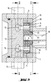
- FIG. 1 through an internal gear pump shows the cast metal housing of the pump (1), which surrounds the casing of the housing (2) made of carbon of the working chamber (3) in a protective and supportive manner, seen from the outside inwards.
- the bearing zone (4) shown here as too large a gap between the housing made of the carbon material (2) and the radially outer running surface (5) of the external gear (6).
- the external gear (6) has an internal toothing (7) which has one tooth more than the external toothing (8) of the internal gear (9) running in it.
- the internal gear (9) is driven by a shaft (10) arranged eccentrically in the pump housing.
- the external gear (6) is arranged centrally in the working chamber (3).
- the internal gear (9) On the side of the shaft (10), the internal gear (9) has a concentric cylindrical elevation (17) which is mounted in the additional bearing (18) shown in FIG. 3, which serves to increase the smooth running of the pump.
- Figure 2 shows a cross section through a block of a Carbon material that is one of the side walls of the Working chamber (3) forms.
- the block is from one again Housing (1) made of cast metal, in which the Intake (16) and the pressure channel (15) of the pump are molded are.
- the intake duct (16) is called the “suction kidney” Recess (12) in the side wall of the working chamber (3) and the pressure channel (15) with the recess called “pressure kidney” (14) connected in the side wall of the working chamber (3).
- the gears rotating in the working chamber (3) (6) and (9) are on the surface of the side wall forming blocks of carbon shown here slidably mounted and the external gear (6) slides as in Fig. 1 reproduced, in addition with its outer Tread (5) on the inner wall of the casing of the housing from carbon (2) of the working chamber (3) as another Camp.
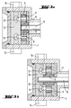
- Figure 3 shows a cross section through the working chamber (3) an internal gear pump parallel to the direction the shaft (10) of the internal gear (9).
- the internal gear (9) has a cylindrical one arranged concentrically around its shaft (10) Elevation (17) with a radial bearing surface (22), in a complementary counter bearing surface (23), which in the bottom of the cup-shaped part of the housing (19) located, fitted and runs in this.
- Figures 4 and 5 show two cross sections through an external gear pump, one of which is parallel to the shafts (24, 24 ') of the gears (25, 25') (Fig. 4) and the other perpendicular to the shafts (24,24 ' ) of the gears (25, 25 ') (Fig. 5) is guided.
- the liquid to be conveyed on the suction side (26) enters the pump driven by one of the shafts (24, 24 ') of the gear wheels (25, 25'), enclosed in the interdental spaces (27) of the counter-rotating gears (25, 25 ') are conveyed into the pressure chamber (28) of the pump and ejected from there from the pump.
- the suction (26) and pressure chamber (28) of the pump are separated from each other by the closely meshing teeth of the gear wheels (25, 25 ').
- the working chamber (3) of the pump is surrounded by a housing made of a carbon material (2) that slides and seals on the tip circle diameter (29) and the side surfaces (30) of the gear wheels (25, 25 ').
- the various carbon parts forming the walls of the working chamber (3) and their function can be clearly seen in FIG.
- the side walls form the blocks 31 and 31 ', which also contain the bearings (32, 32', 32 '', 32 ''') for the shafts (24,24') of the gear wheels (25,25 ').
- the sides of the blocks (31, 31 ') facing the working chamber (3) form the sealing slide bearings for the side surfaces (30) of the gear wheels (25, 25').
- the working chamber (3) is completely surrounded by a jacket made of carbon (2), which lies sealingly and slidingly along the conveying zones (27) formed by the teeth on the tip circle diameter (29) of the gear wheels (25, 25 ').
- This jacket also has the openings for the suction (26) and the pressure channel (28) of the pump.
Landscapes
- Engineering & Computer Science (AREA)
- Mechanical Engineering (AREA)
- General Engineering & Computer Science (AREA)
- Rotary Pumps (AREA)
- Details And Applications Of Rotary Liquid Pumps (AREA)
- Structures Of Non-Positive Displacement Pumps (AREA)
Applications Claiming Priority (2)
| Application Number | Priority Date | Filing Date | Title |
|---|---|---|---|
| DE19710804 | 1997-03-17 | ||
| DE19710804A DE19710804A1 (de) | 1997-03-17 | 1997-03-17 | Zahnradpumpe zum Fördern von Fluiden |
Publications (2)
| Publication Number | Publication Date |
|---|---|
| EP0866224A1 true EP0866224A1 (fr) | 1998-09-23 |
| EP0866224B1 EP0866224B1 (fr) | 2001-10-04 |
Family
ID=7823494
Family Applications (1)
| Application Number | Title | Priority Date | Filing Date |
|---|---|---|---|
| EP98103651A Expired - Lifetime EP0866224B1 (fr) | 1997-03-17 | 1998-03-03 | Pompe à engrenages pour le déplacement de fluides |
Country Status (7)
| Country | Link |
|---|---|
| US (1) | US6053718A (fr) |
| EP (1) | EP0866224B1 (fr) |
| JP (1) | JPH10259785A (fr) |
| KR (1) | KR19980080338A (fr) |
| DE (2) | DE19710804A1 (fr) |
| DK (1) | DK0866224T3 (fr) |
| ES (1) | ES2163816T3 (fr) |
Cited By (9)
| Publication number | Priority date | Publication date | Assignee | Title |
|---|---|---|---|---|
| US6612821B1 (en) | 2000-07-14 | 2003-09-02 | Fluid Management, Inc. | Pump, in particular gear pump including ceramic gears and seal |
| RU2278300C1 (ru) * | 2005-06-01 | 2006-06-20 | ООО "Научно-производственное объединение "Орион ВДМ" | Шестеренный насос |
| RU2307260C1 (ru) * | 2006-06-09 | 2007-09-27 | ООО "Рос ДМ" | Шестеренный дозирующий насос |
| RU2314435C1 (ru) * | 2006-11-15 | 2008-01-10 | ООО "Научно-производственное объединение "Орион ВДМ" | Шестеренный насос-дозатор |
| EP2208889A1 (fr) * | 2009-01-20 | 2010-07-21 | BSH Bosch und Siemens Hausgeräte GmbH | Appareil de boisson |
| WO2010133390A3 (fr) * | 2009-05-22 | 2012-03-15 | Robert Bosch Gmbh | Carter de pompe d'un modulateur hydraulique pour véhicule à moteur |
| US8951027B2 (en) | 2011-10-25 | 2015-02-10 | Danfoss A/S | Vane cell machine |
| US9279424B2 (en) | 2011-10-25 | 2016-03-08 | Danfoss A/S | Vane cell machine having plates containing axial moving inserts bearing against the rotor |
| EP4166751A1 (fr) * | 2021-10-15 | 2023-04-19 | Atlas Copco Airpower N.V. | Compresseur non lubrifié doté d'un élément d'étanchéité abrasible et procédé d'assemblage associé |
Families Citing this family (26)
| Publication number | Priority date | Publication date | Assignee | Title |
|---|---|---|---|---|
| DE19825376C2 (de) * | 1998-06-06 | 2003-12-11 | Bosch Gmbh Robert | Zahnradmaschine |
| DE19826367C2 (de) * | 1998-06-12 | 2000-05-18 | Geraete & Pumpenbau Gmbh | Innenzahnradpumpe |
| DE10019516A1 (de) * | 2000-04-20 | 2001-10-31 | Hoehn Bernd Robert | Zahnräder aus korrosionsbeständigen Stahl |
| ATE348956T1 (de) * | 2001-01-22 | 2007-01-15 | Hnp Mikrosysteme Gmbh | Präzise kleinstlagerung und montageverfahren dafür |
| DE10114148C1 (de) * | 2001-03-22 | 2002-06-06 | Dieter Brox | Selbstzentrierende Zahnradpumpe |
| DE10128055C2 (de) * | 2001-06-01 | 2003-09-25 | Sgl Carbon Ag | Gleitpaarung für von Wasserdampf mit hohem Druck-und Temperaturniveau beaufschlagte Maschinenteile, vorzugsweise für Kolben-Zylinder-Anordnungen von Dampfmotoren |
| US6592348B1 (en) * | 2002-03-27 | 2003-07-15 | Production Research, Inc | Lubricant pump and method of producing |
| US6997689B2 (en) * | 2003-02-20 | 2006-02-14 | Honeywell International Inc. | Offset bearing for extended fuel pump life |
| DE10327321A1 (de) * | 2003-06-16 | 2005-01-13 | Siemens Ag | Als G-Rotorpumpe ausgebildete Verdrängerpumpe |
| KR20050093981A (ko) * | 2004-03-17 | 2005-09-26 | 민경은 | 열경화성 수지를 이용한 미케니컬 씰의 조성물 및 그의제조방법 |
| WO2006015218A1 (fr) * | 2004-07-30 | 2006-02-09 | Pulsafeeder, Inc. | Pompe à engrenages non métallique avec ensemble d'accouplement magnétique |
| US7220111B2 (en) * | 2004-08-02 | 2007-05-22 | Production Research, Llc | Hydraulic pump |
| US7017340B2 (en) * | 2004-08-18 | 2006-03-28 | Ford Global Technologies, Llc | Hydrokinetic torque converter for an automatic vehicle transmission |
| US20060047065A1 (en) * | 2004-08-30 | 2006-03-02 | Wiebke Becker | Aqueous coating compositions based on acrylate copolymers |
| ES2378989T3 (es) * | 2004-10-27 | 2012-04-19 | Sgl Carbon Se | Cuerpo de material deslizante resistente al desgaste de grafito y aglutinante de resina sintética |
| RU2493751C2 (ru) * | 2008-04-09 | 2013-09-27 | Нестек С.А. | Шестеренные насосы и способы их использования |
| JP4977112B2 (ja) * | 2008-11-17 | 2012-07-18 | 日立オートモティブシステムズ株式会社 | ギヤポンプ |
| US8840385B2 (en) | 2011-03-03 | 2014-09-23 | Ti Group Automotive Systems, L.L.C. | Positive displacement fluid pump |
| JP2012202254A (ja) * | 2011-03-24 | 2012-10-22 | Hitachi Automotive Systems Ltd | ポンプ装置 |
| CN102678541B (zh) * | 2012-05-25 | 2014-08-06 | 山东鑫亚工业股份有限公司 | 悬浮式摆线转子输油泵 |
| DE102013201384A1 (de) * | 2013-01-29 | 2014-07-31 | Robert Bosch Gmbh | Innenzahnradpumpe |
| JP6086239B2 (ja) * | 2013-08-09 | 2017-03-01 | アイシン精機株式会社 | 流体ポンプ用インナロータ |
| JP2016205170A (ja) * | 2015-04-17 | 2016-12-08 | セイコーエプソン株式会社 | ギヤポンプおよびこれを備えた印刷装置 |
| DE102015225734A1 (de) | 2015-12-17 | 2017-06-22 | Robert Bosch Gmbh | Innenzahnradpumpe |
| KR20180065312A (ko) * | 2016-12-07 | 2018-06-18 | 엘지전자 주식회사 | 의류처리장치 |
| DE102021004717A1 (de) * | 2021-09-20 | 2023-03-23 | Oerlikon Textile Gmbh & Co. Kg | Dosierpumpe zum Fördern von abrasiven Fluiden |
Citations (3)
| Publication number | Priority date | Publication date | Assignee | Title |
|---|---|---|---|---|
| US2611323A (en) * | 1948-11-30 | 1952-09-23 | Harold D Digney | Pump |
| DE2422783A1 (de) * | 1974-05-10 | 1975-11-27 | Siemens Ag | Vorrichtung zur foerderung von fluessigen medien, insbesondere zur foerderung von kraftstoffen in kraftfahrzeugen |
| JPS57148084A (en) * | 1981-03-09 | 1982-09-13 | Matsushita Electric Ind Co Ltd | Pump device for sprayer |
Family Cites Families (10)
| Publication number | Priority date | Publication date | Assignee | Title |
|---|---|---|---|---|
| US2619040A (en) * | 1949-03-15 | 1952-11-25 | Maisch Oliver | Liquid measuring and dispensing pump |
| GB1236935A (en) * | 1967-09-02 | 1971-06-23 | Plessey Co Ltd | Improvements in or relating to gear pumps more particularly for use with hot hydrocarbon liquid fuels |
| DE7802765U1 (de) * | 1978-01-31 | 1979-10-31 | Allweiler Ag, 7760 Radolfzell | Schraubenspindelmaschine |
| DE2938276A1 (de) * | 1979-09-21 | 1981-04-09 | Robert Bosch Gmbh, 7000 Stuttgart | Fluegelzellenverdichter |
| JPS58220989A (ja) * | 1982-06-14 | 1983-12-22 | Diesel Kiki Co Ltd | 可変容量式ベ−ン型圧縮機 |
| DE3340748C2 (de) * | 1983-11-10 | 1986-09-25 | Fresenius AG, 6380 Bad Homburg | Zahnradpumpe, insbesondere für medizinische Zwecke |
| JPS60204992A (ja) * | 1984-03-29 | 1985-10-16 | Diesel Kiki Co Ltd | ベ−ン型圧縮機 |
| US4804317A (en) * | 1987-03-13 | 1989-02-14 | Eaton Corporation | Rotary vane pump with floating rotor side plates |
| DE4021500C3 (de) * | 1990-07-05 | 1998-10-22 | Mannesmann Vdo Ag | Förderaggregat, insbesondere zum Fördern von Kraftstoff |
| US5181844A (en) * | 1991-08-15 | 1993-01-26 | Sigma Tek, Inc. | Rotary vane pump with carbon/carbon vanes |
-
1997
- 1997-03-17 DE DE19710804A patent/DE19710804A1/de not_active Withdrawn
-
1998
- 1998-03-03 DK DK98103651T patent/DK0866224T3/da active
- 1998-03-03 DE DE59801606T patent/DE59801606D1/de not_active Expired - Lifetime
- 1998-03-03 ES ES98103651T patent/ES2163816T3/es not_active Expired - Lifetime
- 1998-03-03 EP EP98103651A patent/EP0866224B1/fr not_active Expired - Lifetime
- 1998-03-13 JP JP10082941A patent/JPH10259785A/ja active Pending
- 1998-03-17 US US09/042,788 patent/US6053718A/en not_active Expired - Fee Related
- 1998-03-17 KR KR1019980008937A patent/KR19980080338A/ko not_active Withdrawn
Patent Citations (3)
| Publication number | Priority date | Publication date | Assignee | Title |
|---|---|---|---|---|
| US2611323A (en) * | 1948-11-30 | 1952-09-23 | Harold D Digney | Pump |
| DE2422783A1 (de) * | 1974-05-10 | 1975-11-27 | Siemens Ag | Vorrichtung zur foerderung von fluessigen medien, insbesondere zur foerderung von kraftstoffen in kraftfahrzeugen |
| JPS57148084A (en) * | 1981-03-09 | 1982-09-13 | Matsushita Electric Ind Co Ltd | Pump device for sprayer |
Non-Patent Citations (1)
| Title |
|---|
| PATENT ABSTRACTS OF JAPAN vol. 6, no. 253 (M - 178)<1131> 11 December 1982 (1982-12-11) * |
Cited By (13)
| Publication number | Priority date | Publication date | Assignee | Title |
|---|---|---|---|---|
| US6612821B1 (en) | 2000-07-14 | 2003-09-02 | Fluid Management, Inc. | Pump, in particular gear pump including ceramic gears and seal |
| RU2278300C1 (ru) * | 2005-06-01 | 2006-06-20 | ООО "Научно-производственное объединение "Орион ВДМ" | Шестеренный насос |
| RU2307260C1 (ru) * | 2006-06-09 | 2007-09-27 | ООО "Рос ДМ" | Шестеренный дозирующий насос |
| RU2314435C1 (ru) * | 2006-11-15 | 2008-01-10 | ООО "Научно-производственное объединение "Орион ВДМ" | Шестеренный насос-дозатор |
| EP2208889A1 (fr) * | 2009-01-20 | 2010-07-21 | BSH Bosch und Siemens Hausgeräte GmbH | Appareil de boisson |
| WO2010133390A3 (fr) * | 2009-05-22 | 2012-03-15 | Robert Bosch Gmbh | Carter de pompe d'un modulateur hydraulique pour véhicule à moteur |
| US8951027B2 (en) | 2011-10-25 | 2015-02-10 | Danfoss A/S | Vane cell machine |
| US9279424B2 (en) | 2011-10-25 | 2016-03-08 | Danfoss A/S | Vane cell machine having plates containing axial moving inserts bearing against the rotor |
| EP4166751A1 (fr) * | 2021-10-15 | 2023-04-19 | Atlas Copco Airpower N.V. | Compresseur non lubrifié doté d'un élément d'étanchéité abrasible et procédé d'assemblage associé |
| WO2023062479A1 (fr) * | 2021-10-15 | 2023-04-20 | Atlas Copco Airpower, Naamloze Vennootschap | Compresseur non lubrifié doté d'un élément d'étanchéité abradable et son procédé d'assemblage |
| BE1029799B1 (nl) * | 2021-10-15 | 2023-09-01 | Atlas Copco Airpower Nv | Niet-gesmeerde compressor met slijtwillig afdichtingselement en verwante werkwijze om deze te monteren |
| MA65666A1 (fr) * | 2021-10-15 | 2024-07-31 | Atlas Copco Airpower, Naamloze Vennootschap | Compresseur non lubrifié doté d'un élément d'étanchéité abradable et son procédé d'assemblage |
| US12345262B2 (en) | 2021-10-15 | 2025-07-01 | Atlas Copco Airpower, Naamloze Vennootschap | Non-lubricated compressor with abradable sealing element and related method for assembling it |
Also Published As
| Publication number | Publication date |
|---|---|
| DE59801606D1 (de) | 2001-11-08 |
| US6053718A (en) | 2000-04-25 |
| DK0866224T3 (da) | 2002-01-28 |
| JPH10259785A (ja) | 1998-09-29 |
| DE19710804A1 (de) | 1998-09-24 |
| EP0866224B1 (fr) | 2001-10-04 |
| KR19980080338A (ko) | 1998-11-25 |
| ES2163816T3 (es) | 2002-02-01 |
Similar Documents
| Publication | Publication Date | Title |
|---|---|---|
| EP0866224B1 (fr) | Pompe à engrenages pour le déplacement de fluides | |
| DE10066044B4 (de) | Verfahren zum Herstellen eines Reibkörpers aus siliziumfiltriertem, Kohlenstofffaser verstärktem porösen Kohlenstoff und Verwendung eines solchen Reibkörpers | |
| DE68906805T2 (de) | Materialverbindung aus flexiblen Graphitteilchen und unkristallisiertem Kohlenstoff. | |
| DE3855544T2 (de) | Keramische Verbundwerkstoff und Verfahren zur Herstellung desselben | |
| DE3312868C2 (de) | Hydropumpe | |
| EP3380444B1 (fr) | Élément en plastique chargé carbone | |
| DE2353551B2 (de) | Keramisches Turbinenlaufrad | |
| DE69200935T2 (de) | Zahnraddosierpumpe für elastomeres Material. | |
| DE2750137A1 (de) | Kreiselpumpe bzw. -verdichter | |
| EP0464261A1 (fr) | Pompe d'alimentation en combustible | |
| DE19815989A1 (de) | Kolben-Zylinder-Anordnung | |
| EP1337737B1 (fr) | Systeme d'association coulissante pour pieces de machine qui sont soumises a l'effet d'une vapeur d'eau a pression et temperature elevees, de preference pour ensembles piston-cylindre de moteurs a vapeur | |
| EP1489331B1 (fr) | Corps de friction en carbone poreux renforcé par des fibres et infiltré de métal | |
| DE2362940A1 (de) | Dichtungselement fuer den kolben eines verbrennungsmotors | |
| CH646763A5 (de) | Wellendichtung fuer hydraulische maschinen. | |
| EP2654935B1 (fr) | Mélangeur dynamique | |
| DE3506475C2 (fr) | ||
| DE102010055682A1 (de) | Gehäuse einer Außenzahnradmaschine und Außenzahnradmaschine | |
| WO2004101836A2 (fr) | Pompe a huile | |
| DE10032044B4 (de) | Gleitlager mit Festschmierstoff | |
| DE2422783A1 (de) | Vorrichtung zur foerderung von fluessigen medien, insbesondere zur foerderung von kraftstoffen in kraftfahrzeugen | |
| EP0717019B1 (fr) | Garniture étanche à anneau glissant en carbone | |
| EP0900610B1 (fr) | Procédé de préparation de palier en métal fritté pour arbre céramique ainsi que palier obtenu | |
| AT519398A1 (de) | Verfahren zur Herstellung einer Taumelscheibe | |
| DE918909C (de) | Geschlitzter Kolbenring |
Legal Events
| Date | Code | Title | Description |
|---|---|---|---|
| PUAI | Public reference made under article 153(3) epc to a published international application that has entered the european phase |
Free format text: ORIGINAL CODE: 0009012 |
|
| 17P | Request for examination filed |
Effective date: 19980717 |
|
| AK | Designated contracting states |
Kind code of ref document: A1 Designated state(s): BE CH DE DK ES FR GB IE IT LI NL SE |
|
| AX | Request for extension of the european patent |
Free format text: AL;LT;LV;MK;RO;SI |
|
| AKX | Designation fees paid |
Free format text: BE CH DE DK ES FR GB IE IT LI NL SE |
|
| RBV | Designated contracting states (corrected) |
Designated state(s): BE CH DE DK ES FR GB IE IT LI NL SE |
|
| GRAG | Despatch of communication of intention to grant |
Free format text: ORIGINAL CODE: EPIDOS AGRA |
|
| GRAG | Despatch of communication of intention to grant |
Free format text: ORIGINAL CODE: EPIDOS AGRA |
|
| GRAH | Despatch of communication of intention to grant a patent |
Free format text: ORIGINAL CODE: EPIDOS IGRA |
|
| 17Q | First examination report despatched |
Effective date: 20010226 |
|
| GRAH | Despatch of communication of intention to grant a patent |
Free format text: ORIGINAL CODE: EPIDOS IGRA |
|
| GRAA | (expected) grant |
Free format text: ORIGINAL CODE: 0009210 |
|
| AK | Designated contracting states |
Kind code of ref document: B1 Designated state(s): BE CH DE DK ES FR GB IE IT LI NL SE |
|
| REG | Reference to a national code |
Ref country code: CH Ref legal event code: NV Representative=s name: PATENTANWAELTE BREITER + WIEDMER AG Ref country code: CH Ref legal event code: EP |
|
| REF | Corresponds to: |
Ref document number: 59801606 Country of ref document: DE Date of ref document: 20011108 |
|
| REG | Reference to a national code |
Ref country code: IE Ref legal event code: FG4D Free format text: GERMAN |
|
| ET | Fr: translation filed | ||
| REG | Reference to a national code |
Ref country code: GB Ref legal event code: IF02 |
|
| GBT | Gb: translation of ep patent filed (gb section 77(6)(a)/1977) |
Effective date: 20020102 |
|
| REG | Reference to a national code |
Ref country code: DK Ref legal event code: T3 |
|
| REG | Reference to a national code |
Ref country code: ES Ref legal event code: FG2A Ref document number: 2163816 Country of ref document: ES Kind code of ref document: T3 |
|
| PG25 | Lapsed in a contracting state [announced via postgrant information from national office to epo] |
Ref country code: IE Free format text: LAPSE BECAUSE OF NON-PAYMENT OF DUE FEES Effective date: 20020304 Ref country code: ES Free format text: LAPSE BECAUSE OF NON-PAYMENT OF DUE FEES Effective date: 20020304 |
|
| PG25 | Lapsed in a contracting state [announced via postgrant information from national office to epo] |
Ref country code: LI Free format text: LAPSE BECAUSE OF NON-PAYMENT OF DUE FEES Effective date: 20020331 Ref country code: CH Free format text: LAPSE BECAUSE OF NON-PAYMENT OF DUE FEES Effective date: 20020331 Ref country code: BE Free format text: LAPSE BECAUSE OF NON-PAYMENT OF DUE FEES Effective date: 20020331 |
|
| PLBQ | Unpublished change to opponent data |
Free format text: ORIGINAL CODE: EPIDOS OPPO |
|
| PLBI | Opposition filed |
Free format text: ORIGINAL CODE: 0009260 |
|
| PLBF | Reply of patent proprietor to notice(s) of opposition |
Free format text: ORIGINAL CODE: EPIDOS OBSO |
|
| 26 | Opposition filed |
Opponent name: WILO GMBH Effective date: 20020702 |
|
| BERE | Be: lapsed |
Owner name: *GERATE- UND PUMPENBAU G.M.B.H. Effective date: 20020331 Owner name: *SGL CARBON A.G. Effective date: 20020331 |
|
| PG25 | Lapsed in a contracting state [announced via postgrant information from national office to epo] |
Ref country code: NL Free format text: LAPSE BECAUSE OF NON-PAYMENT OF DUE FEES Effective date: 20021001 |
|
| NLR1 | Nl: opposition has been filed with the epo |
Opponent name: WILO GMBH |
|
| REG | Reference to a national code |
Ref country code: CH Ref legal event code: PL |
|
| NLV4 | Nl: lapsed or anulled due to non-payment of the annual fee |
Effective date: 20021001 |
|
| REG | Reference to a national code |
Ref country code: IE Ref legal event code: MM4A |
|
| PLBF | Reply of patent proprietor to notice(s) of opposition |
Free format text: ORIGINAL CODE: EPIDOS OBSO |
|
| PLCK | Communication despatched that opposition was rejected |
Free format text: ORIGINAL CODE: EPIDOSNREJ1 |
|
| PLBN | Opposition rejected |
Free format text: ORIGINAL CODE: 0009273 |
|
| STAA | Information on the status of an ep patent application or granted ep patent |
Free format text: STATUS: OPPOSITION REJECTED |
|
| REG | Reference to a national code |
Ref country code: ES Ref legal event code: FD2A Effective date: 20030410 |
|
| 27O | Opposition rejected |
Effective date: 20031229 |
|
| PLAB | Opposition data, opponent's data or that of the opponent's representative modified |
Free format text: ORIGINAL CODE: 0009299OPPO |
|
| PGFP | Annual fee paid to national office [announced via postgrant information from national office to epo] |
Ref country code: DK Payment date: 20100310 Year of fee payment: 13 |
|
| PGFP | Annual fee paid to national office [announced via postgrant information from national office to epo] |
Ref country code: IT Payment date: 20100327 Year of fee payment: 13 Ref country code: FR Payment date: 20100402 Year of fee payment: 13 |
|
| PGFP | Annual fee paid to national office [announced via postgrant information from national office to epo] |
Ref country code: GB Payment date: 20100322 Year of fee payment: 13 |
|
| PGFP | Annual fee paid to national office [announced via postgrant information from national office to epo] |
Ref country code: SE Payment date: 20100312 Year of fee payment: 13 |
|
| PGFP | Annual fee paid to national office [announced via postgrant information from national office to epo] |
Ref country code: DE Payment date: 20110331 Year of fee payment: 14 |
|
| REG | Reference to a national code |
Ref country code: DK Ref legal event code: EBP |
|
| REG | Reference to a national code |
Ref country code: SE Ref legal event code: EUG |
|
| GBPC | Gb: european patent ceased through non-payment of renewal fee |
Effective date: 20110303 |
|
| REG | Reference to a national code |
Ref country code: FR Ref legal event code: ST Effective date: 20111130 |
|
| PG25 | Lapsed in a contracting state [announced via postgrant information from national office to epo] |
Ref country code: FR Free format text: LAPSE BECAUSE OF NON-PAYMENT OF DUE FEES Effective date: 20110331 |
|
| PG25 | Lapsed in a contracting state [announced via postgrant information from national office to epo] |
Ref country code: IT Free format text: LAPSE BECAUSE OF NON-PAYMENT OF DUE FEES Effective date: 20110303 Ref country code: GB Free format text: LAPSE BECAUSE OF NON-PAYMENT OF DUE FEES Effective date: 20110303 |
|
| PG25 | Lapsed in a contracting state [announced via postgrant information from national office to epo] |
Ref country code: DK Free format text: LAPSE BECAUSE OF NON-PAYMENT OF DUE FEES Effective date: 20110331 |
|
| REG | Reference to a national code |
Ref country code: DE Ref legal event code: R119 Ref document number: 59801606 Country of ref document: DE Effective date: 20121002 |
|
| PG25 | Lapsed in a contracting state [announced via postgrant information from national office to epo] |
Ref country code: SE Free format text: LAPSE BECAUSE OF NON-PAYMENT OF DUE FEES Effective date: 20110304 |
|
| PG25 | Lapsed in a contracting state [announced via postgrant information from national office to epo] |
Ref country code: DE Free format text: LAPSE BECAUSE OF NON-PAYMENT OF DUE FEES Effective date: 20121002 |