EP0866239A2 - Boíte de vitesses à plusieurs rapports à commande manuelle avec dispositif de freinage pour marche arrière - Google Patents
Boíte de vitesses à plusieurs rapports à commande manuelle avec dispositif de freinage pour marche arrière Download PDFInfo
- Publication number
- EP0866239A2 EP0866239A2 EP98103040A EP98103040A EP0866239A2 EP 0866239 A2 EP0866239 A2 EP 0866239A2 EP 98103040 A EP98103040 A EP 98103040A EP 98103040 A EP98103040 A EP 98103040A EP 0866239 A2 EP0866239 A2 EP 0866239A2
- Authority
- EP
- European Patent Office
- Prior art keywords
- gear
- input
- input shaft
- output shaft
- shaft
- Prior art date
- Legal status (The legal status is an assumption and is not a legal conclusion. Google has not performed a legal analysis and makes no representation as to the accuracy of the status listed.)
- Granted
Links
- 230000005540 biological transmission Effects 0.000 title claims abstract description 56
- 230000007246 mechanism Effects 0.000 claims description 15
- 230000008878 coupling Effects 0.000 claims description 14
- 238000010168 coupling process Methods 0.000 claims description 14
- 238000005859 coupling reaction Methods 0.000 claims description 14
- 230000004044 response Effects 0.000 claims description 11
- 230000002401 inhibitory effect Effects 0.000 claims 1
- 230000007935 neutral effect Effects 0.000 description 13
- 230000001360 synchronised effect Effects 0.000 description 5
- 238000010586 diagram Methods 0.000 description 2
- 238000000034 method Methods 0.000 description 2
- 241000054879 Pteris denticulata Species 0.000 description 1
- 230000000712 assembly Effects 0.000 description 1
- 238000000429 assembly Methods 0.000 description 1
- 238000010276 construction Methods 0.000 description 1
- 230000004069 differentiation Effects 0.000 description 1
- 230000004048 modification Effects 0.000 description 1
- 238000012986 modification Methods 0.000 description 1
- 230000008569 process Effects 0.000 description 1
Images

Classifications
-
- F—MECHANICAL ENGINEERING; LIGHTING; HEATING; WEAPONS; BLASTING
- F16—ENGINEERING ELEMENTS AND UNITS; GENERAL MEASURES FOR PRODUCING AND MAINTAINING EFFECTIVE FUNCTIONING OF MACHINES OR INSTALLATIONS; THERMAL INSULATION IN GENERAL
- F16H—GEARING
- F16H3/00—Toothed gearings for conveying rotary motion with variable gear ratio or for reversing rotary motion
- F16H3/02—Toothed gearings for conveying rotary motion with variable gear ratio or for reversing rotary motion without gears having orbital motion
- F16H3/20—Toothed gearings for conveying rotary motion with variable gear ratio or for reversing rotary motion without gears having orbital motion exclusively or essentially using gears that can be moved out of gear
- F16H3/38—Toothed gearings for conveying rotary motion with variable gear ratio or for reversing rotary motion without gears having orbital motion exclusively or essentially using gears that can be moved out of gear with synchro-meshing
- F16H3/385—Toothed gearings for conveying rotary motion with variable gear ratio or for reversing rotary motion without gears having orbital motion exclusively or essentially using gears that can be moved out of gear with synchro-meshing with braking means
-
- F—MECHANICAL ENGINEERING; LIGHTING; HEATING; WEAPONS; BLASTING
- F16—ENGINEERING ELEMENTS AND UNITS; GENERAL MEASURES FOR PRODUCING AND MAINTAINING EFFECTIVE FUNCTIONING OF MACHINES OR INSTALLATIONS; THERMAL INSULATION IN GENERAL
- F16H—GEARING
- F16H63/00—Control outputs from the control unit to change-speed- or reversing-gearings for conveying rotary motion or to other devices than the final output mechanism
- F16H63/02—Final output mechanisms therefor; Actuating means for the final output mechanisms
- F16H63/30—Constructional features of the final output mechanisms
- F16H63/302—Final output mechanisms for reversing
-
- Y—GENERAL TAGGING OF NEW TECHNOLOGICAL DEVELOPMENTS; GENERAL TAGGING OF CROSS-SECTIONAL TECHNOLOGIES SPANNING OVER SEVERAL SECTIONS OF THE IPC; TECHNICAL SUBJECTS COVERED BY FORMER USPC CROSS-REFERENCE ART COLLECTIONS [XRACs] AND DIGESTS
- Y10—TECHNICAL SUBJECTS COVERED BY FORMER USPC
- Y10T—TECHNICAL SUBJECTS COVERED BY FORMER US CLASSIFICATION
- Y10T74/00—Machine element or mechanism
- Y10T74/19—Gearing
- Y10T74/19219—Interchangeably locked
- Y10T74/19223—Disconnectable counter shaft
-
- Y—GENERAL TAGGING OF NEW TECHNOLOGICAL DEVELOPMENTS; GENERAL TAGGING OF CROSS-SECTIONAL TECHNOLOGIES SPANNING OVER SEVERAL SECTIONS OF THE IPC; TECHNICAL SUBJECTS COVERED BY FORMER USPC CROSS-REFERENCE ART COLLECTIONS [XRACs] AND DIGESTS
- Y10—TECHNICAL SUBJECTS COVERED BY FORMER USPC
- Y10T—TECHNICAL SUBJECTS COVERED BY FORMER US CLASSIFICATION
- Y10T74/00—Machine element or mechanism
- Y10T74/19—Gearing
- Y10T74/19219—Interchangeably locked
- Y10T74/19233—Plurality of counter shafts
-
- Y—GENERAL TAGGING OF NEW TECHNOLOGICAL DEVELOPMENTS; GENERAL TAGGING OF CROSS-SECTIONAL TECHNOLOGIES SPANNING OVER SEVERAL SECTIONS OF THE IPC; TECHNICAL SUBJECTS COVERED BY FORMER USPC CROSS-REFERENCE ART COLLECTIONS [XRACs] AND DIGESTS
- Y10—TECHNICAL SUBJECTS COVERED BY FORMER USPC
- Y10T—TECHNICAL SUBJECTS COVERED BY FORMER US CLASSIFICATION
- Y10T74/00—Machine element or mechanism
- Y10T74/19—Gearing
- Y10T74/19219—Interchangeably locked
- Y10T74/19242—Combined gear and clutch
Definitions
- the present invention relates generally to multi-speed transmissions for use in motor vehicles. More specifically, the present invention is directed to a manual transmission having a reverse brake arrangement.
- manual transmissions are shifted by the vehicle operator moving a gearshift lever which functions, through a shift mechanism, to selectively engage one of a plurality of gearsets for driving the output shaft in a first direction and at a predetermined speed ratio relative to the input shaft.
- gearshift lever which functions, through a shift mechanism, to selectively engage one of a plurality of gearsets for driving the output shaft in a first direction and at a predetermined speed ratio relative to the input shaft.
- most manual transmissions include a plurality of synchromesh gearsets which can be selectively engaged for establishing the different forward gears.
- many manual transmissions are equipped with a reverse idler assembly which can be selectively engaged for establishing the reverse gear.
- the reverse idler assembly includes a reverse input gear driven by the input shaft, a reverse output gear driven by the output shaft, and a reverse idler gear which is selectively movable into meshed engagement with the reverse input gear and the reverse output gear for driving the output shaft in a second direction and at a predetermined speed ratio relative to the input shaft for establishing the reverse gear.
- one of the forward gears is typically disengaged immediately prior to selection of the reverse gear.
- the input shaft is free to continue rotating due to inertia under a substantially no-load condition until, through friction and windage losses, the inertia of the input shaft is dissipated and rotation is arrested. If the vehicle operators moves the gearshift lever in an attempt to engage the reverse idler gear while the input shaft is still rotating, the teeth of the reverse idler gear will strike the teeth of the reverse input gear. As such, the force applied by the vehicle operator through the gearshift lever results in an undesirable clattering as the teeth of the reverse idler gear are forced into contact with the teeth of the reverse input gear, but yet are unable to mesh therewith because of the relative rotational speeds.
- reverse clash This condition, commonly referred to as "reverse clash", results in an unpleasant grinding noise and the clashing is felt by the vehicle operator.
- the vehicle operator must wait for the input shaft to stop rotating before the gearshift lever can be moved quietly and smoothly to engage the reverse gear.
- any time delay required before the gearshift lever can be moved to engage reverse gear in order to avoid the occurrence of reverse clash is objectionable.
- reverse clash can be virtually eliminated by stopping rotation of the input shaft before an attempt is made to engage the reverse idler gear with the reverse input gear.
- the present invention is directed to a multi-speed manual transmission for use in motor vehicles having a geartrain arranged to use a common gearset for establishing a forward gear and braking rotation of the input shaft.
- the transmission includes: an input shaft; an output shaft; a gearset including a first gear rotatably supported on the input shaft, and a second gear fixed to the output shaft and meshed with the first gear; a first synchronizer clutch movable from a first position displaced from the gearset toward a second position for causing speed synchronization between the input shaft and the first gear, the first synchronizer clutch is further operable in its second position for releasably coupling said input gear to said input shaft for driving the output shaft in a first direction relative to the input shaft to establish a forward gear; a third gear movable between a first position disengaged from meshed engagement with the input and output shafts and a second position in meshed engagement therewith for driving the output shaft in a second direction relative to the input shaft to establish a reverse gear; a
- the gearset is arranged such that the first gear is fixed to the input shaft, the second gear is rotatably supported from the output shaft, the first synchronizer functions to releasably couple the output shaft to the gearset for establishing the forward gear, and the second synchronizer is movable between from its first position to its second position to cause speed synchronization between the output shaft and the input shaft which results in the braking of the input shaft.
- the present invention is directed to a reverse brake incorporated into the geartrain of a manual transmission which functions to stop inertial rotation of the input shaft prior to engagement of reverse gear.
- a constant-mesh gearset is operable with a first clutch to establish a forward drive connection between the input shaft and the output shaft, and is further operable with a second clutch to brake rotation of the input shaft without establishing a forward drive connection with the output shaft.
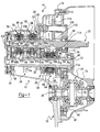
- transmission 10 includes a multi-speed geartrain 12, a reverse idler assembly 14, and a power transfer mechanism 16, all of which are operably mounted within a transmission housing 18.
- Geartrain 12 includes an input shaft 20 which is adapted to be rotatably driven by the output shaft of the motor vehicle's engine and which is connectable thereto through engagement of a manually-operable clutch (not shown).
- Geartrain 12 also includes an output shaft 22 and a series of constant-mesh gearsets 24, 26, 28, 30 and 32.
- Each gearset can be selectively engaged for coupling output shaft 22 to input shaft 20 and establishing five different forward speed ratios (i.e., five forward gears). Engagement of any one of the constant-mesh gearsets results in driven rotation of output shaft 22 in a first direction relative to input shaft 20.
- reverse idler assembly 14 can be selectively engaged for coupling output shaft 22 to input shaft 20 and establishing a reverse speed ratio (i.e., reverse gear). Engagement of rear idler assembly 14 results in driven rotation of output shaft 22 in a second direction relative to input shaft 20.
- Power transfer mechanism 16 is rotatably driven by output shaft 22 and includes a differential assembly 34 that is operable for delivering drive torque through a pair of side gears 36 to a pair of front wheel drive shafts (not shown).
- a drive gear 38 is shown fixed to housing 40 of differential assembly 34 and is in constant meshed engagement with an output gear 42 formed on output shaft 22.
- driven rotation of housing 40 results in side gears 36 being rotatively driven while permitting speed differentiation therebetween.
- input shaft 20, output shaft 22, reverse idler assembly 14 and differential assembly 34 are all rotatably supported within housing 18 by suitable bearings. While the present invention is specifically disclosed in association with a transaxle-type transmission, it will be understood that the teachings are also applicable to rear wheel drive transmissions wherein power transfer mechanism 16 is eliminated and output shaft 22 is directly coupled to the vehicle's rear driveline.
- first gearset 24 is shown to include a first input gear 44 fixed to input shaft 20 and a first speed gear 46 rotatably supported on output shaft 22.
- First input gear 44 is in constant mesh with first speed gear 46 for defining a first power transmission path from input shaft 20 to output shaft 22 which, when engaged, establishes a drive connection therebetween at a first speed ratio.
- Second gearset 26 includes a second input gear 48 fixed to input shaft 20 and a second speed gear 50 rotatably supported on output shaft 22.
- Second input gear 48 is in constant mesh with second speed gear 50 for defining a second power transmission path from input shaft 20 to output shaft 22 which, when engaged, establishes a drive connection therebetween at a second speed ratio.
- Third gearset 28 includes a third input gear 52 rotatably supported on input shaft 20 which is in constant mesh with a third speed gear 54 fixed to output shaft 22 for defining a third power transmission path from input shaft 20 to output shaft 22 which, when engaged, establishes a drive connection therebetween at a third speed ratio.
- Fourth gearset 30 includes a fourth input gear 56 rotatably supported on input shaft 20 and which is in constant mesh with a fourth speed gear 58 fixed to output shaft 22, thereby defining a fourth power transmission path which, when engaged, establishes a drive connection therebetween at a fourth speed ratio.
- fifth gearset 32 includes a fifth input gear 60 rotatably supported on input shaft 20 and which is in constant mesh with a fifth speed gear 62 fixed to output shaft 22, thereby defining a fifth power transmission path which, when engaged, establishes a drive connection therebetween at a fifth speed ratio.
- geartrain 12 is arranged to selectively deliver drive torque from input shaft 20 to output shaft 22 through one of the five different power transmission paths for establishing five different forward gears.
- each gearset of geartrain 12 is associated with a selectively-engageable synchronizer clutch.
- a first synchronizer clutch 64 is operably installed between first gearset 24 and second gearset 26 and includes a first hub 66 fixed to output shaft 22, a first shift sleeve 68, and a pair of cone-type synchronizers 70a and 70b.
- First synchronizer clutch 64 is of the double-acting variety such that first shift sleeve 68 is splined for common rotation with, and bi-directional axial movement on, first hub 66 for selectively coupling one of first and second gearsets 24 and 26, respectively, to output shaft 22 and establishing either of the first or second forward gears.
- forward axial movement of first shift sleeve 68 from its neutral position shown acts to energize synchronizer 70a for generating a synchronizing cone torque which causes speed synchronization between first gearset 24 and output shaft 22.
- first shift sleeve 68 moves through the teeth on a blocker ring 71a and into locked engagement with clutch teeth 72 on first speed gear 46, thereby engaging the first power transmission path and establishing the first forward gear.
- rearward axial movement of first shift sleeve 68 from its neutral position acts to energize synchronizer 70b for generating a synchronizing cone torque which causes speed synchronization between second gearset 26 and output shaft 22.
- first shift sleeve 68 moves through the teeth on a blocker ring 71b and into locked engagement with clutch teeth 74 on second speed gear 50, thereby engaging the second power transmission path and establishing the second forward gear.
- a second synchronizer clutch 76 is operably installed between third gearset 28 and fourth gearset 30 and includes a second hub 78 fixed to input shaft 20, a second shift sleeve 80, and a pair of cone-type synchronizers 82a and 82b. Second synchronizer clutch 76 is also a double-acting arrangement with second shift sleeve 80 splined on second hub 78 for common rotation therewith and bi-directional axial movement thereon for selectively coupling one of third gearset 28 and fourth gearset 30 to input shaft 20 and establishing either of the third or fourth forward gears.
- second shift sleeve 80 forward axial movement of second shift sleeve 80 from its neutral position shown acts to energize synchronizer 82a for generating a synchronizing cone torque to cause speed synchronization between third gearset 28 and input shaft 20.
- second shift sleeve 80 moves through the teeth on a blocker ring 83a and into locked engagement with clutch teeth 84 formed on a clutch ring 86 which is fixed to third input gear 52, thereby engaging the third power transmission path and establishing third forward gear.
- Rearward axial movement of second shift sleeve 80 from its neutral position acts to energize synchronizer 82b for generating a synchronizing cone torque to cause speed synchronization between fourth gearset 30 and input shaft 20.
- second shift sleeve 80 moves through the teeth on blocker ring 83b and into locked engagement with clutch teeth 88 formed on a clutch ring 90 which is fixed to fourth input gear 56, thereby engaging the fourth power transmission path and establishing the fourth forward gear.
- a third synchronizer clutch 92 is operably installed between third gearset 28 and fifth gearset 32 and includes a third hub 94 fixed to input shaft 20, a pair of synchronizers 96a and 96b, and a third shift sleeve 98.
- Third synchronizer clutch 92 is also of the double-acting variety such that third shift sleeve 98 is splined for common rotation with and bi-directional axial movement on, third hub 94 for either selectively coupling fifth gearset 32 to input shaft 20 or braking rotation of input shaft 20 through third gearset 28 without coupling third gearset 28 thereto.
- third shift sleeve 98 forward axial movement of third shift sleeve 98 from its neutral position shown acts to energize synchronizer 96a for generating a synchronizing cone torque which causes speed synchronization between fifth gearset 32 and input shaft 20.
- third shift sleeve 98 moves through the teeth on a blocker ring 97a into locked engagement with clutch teeth 100 formed on a clutch ring 102 fixed to fifth input gear 60, thereby engaging the fifth power transmission path and establishing the fifth forward gear.
- third shift sleeve 98 Rearward axial movement of third shift sleeve 98 from its neutral position acts to energize synchronizer 96b for generating a synchronizing cone torque which causes speed synchronization between third gearset 28 and input shaft 20.
- rearward axial movement of third shift sleeve 98 results in response to the vehicle operator attempting to shift into the reverse gear. Since the reverse gear is normally selected when the vehicle is in a non-motive condition, the front wheel drive shafts and differential assembly 34 hold output shaft 22 and third speed gear 54 of third gearset 28 against rotation.
- a brake ring 104 is shown fixed to third input gear 52. Brake ring 104 is similar to clutch ring 102 except that brake ring 104 does not have clutch teeth formed thereon. As such, upon complete speed synchronization, third shift sleeve 98 moves through the teeth on a blocker ring 97b but does not lockingly engage brake ring 104, whereby third shift sleeve 98 does not engage third gearset 28.
- a stop ring 106 is provided between brake ring 104 and third input gear 52 to limit rearward movement of third shift sleeve 98.
- each of shift sleeves 68, 80 and 98 is shown centrally positioned in a neutral or non-engaged position for cumulatively establishing a neutral mode in which drive torque is not transferred from input shaft 20 to output shaft to 22 through any of the gearsets or reverse idler assembly 14.
- Synchronizers 70a and 70b are shown to be of the dual-cone variety which are energized by a set of spring-biased struts supported in guideways formed in first hub 66 for limited bi-directional axial movement relative to blocker rings 71a and 71b.
- blocker rings 71a and 71b function to inhibit first shift sleeve 68 from passing therethrough and into respective locked engagement with clutch teeth 72 and 74 until the rotary speed of output shaft 22 is substantially synchronous with that of input shaft 20.
- Synchronizers 82a and 82b are shown to be of the single-cone variety which are also energized by a set of spring-biased struts supported for limited bi-directional axial movement in guideways formed in second hub 78.
- blocker rings 83a and 83b function to inhibit second shift sleeve 80 from passing therethrough and into respective locked engagement with clutch teeth 84 and 88 until the rotary speed of input shaft 20 is substantially equal to that of output shaft 22.
- synchronizers 96a and 96 are also shown to be of the single-cone type which are energized by spring-biased struts supported for limited bi-directional axial movement in guideways formed in third hub 94.
- Blocker ring 97a functions to inhibit third shift sleeve 98 from passing therethrough and into locked engagement with clutch ring 102 until the rotary speed of input shaft 20 is substantially equal to that of output shaft 22.
- blocker ring 97b functions to inhibit third shift sleeve 98 from passing therethrough until the rotary speed of input shaft 20 is equal to that of output shaft 22.
- the synchronizers can be of any conventional construction currently known in the manual transmission art for causing speed synchronization between two relatively rotatable components, with such alternative arrangements considered equivalent to that shown.
- reverse idler assembly 14 is shown in FIG. 1 to include an idler shaft 108 fixed to housing 18, an idler gear 110 rotatably supported on idler shaft 104, a reverse input gear 112 fixed to input shaft 20, and a reverse output gear 114 formed as part of first shift sleeve 68.
- Idler gear 110 is connected by the transmission's shift system to third shift sleeve 98 for coordinated movement therebetween such that idler gear 110 is located in the position shown when third shift sleeve 98 is in its centered neutral position. As such, idler gear 110 is moved forwardly in response to forward movement of third shift sleeve 98 into engagement with clutch ring 102.
- idler gear 110 is moved into the position shown by phantom lines when third shift sleeve 98 is moved rearwardly past brake ring 104.
- idler gear 110 is in the engaged position shown by the phantom lines, it is in meshed engagement with reverse input gear 112 and reverse output gear 114, thereby establishing the reverse gear ratio drive connection between input shaft 20 and output shaft 22. Since the energized engagement of cone-type synchronizer 96b with brake ring 104 results in braking of rotation of input shaft 20, idler gear 110 can move into engagement with reverse input gear 112 and reverse output gear 114 without generating gear clash.
- the present invention is directed to a reverse brake arrangement using a non-toothed brake ring in conjunction with a speed synchronizer for braking the input shaft to an existing input gear.
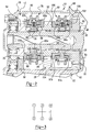
- FIG. 3 shows the gate or shift pattern for the gearshift lever used to establish the five forward gears and the reverse gear.
- FIG. 4 schematically illustrates a shift mechanism 116 which interconnects each of shift sleeves 68, 80 and 98 to a gearshift lever 118 such that the vehicle operator can select the desired gear.
- shift mechanism 116 also interconnects idler gear 110 for coordinated movement with third shift sleeve 98.
- Shift mechanism 116 can be any known mechanical, hydraulic or electrically-actuated system that is capable of controlling movement of shift sleeves 68, 80 and 98 and idler gear 110.
- FIG. 5 shows a portion of transmission 10 having an alternative multi-speed geartrain 12' where all of the input gears are fixed to input shaft 20' and all of the speed gears are rotatably supported on output shaft 22'. Due to the similar function of geartrain 12' to that of geartrain 12, its components are identified by like reference numerals having a primed designation which is indicative of the modified geartrain arrangement.
- third gearset 28' includes a third input gear 52' fixed to input shaft 20' and which is in constant-mesh with a third speed gear 54' rotatably supported on output shaft 22' for defining a third power transmission path from input shaft 20' to output shaft 22' which, when engaged, establishes a drive connection therebetween at a third speed ratio.
- Fourth gearset 30' includes a fourth input gear 56' fixed to input shaft 20' and which is in constant-mesh with a fourth speed gear 58' rotatably supported on output shaft 22', thereby defining a fourth power transmission path, which, when engaged, establishes a drive connection therebetween at a fourth speed ratio.
- Fifth gearset 32' includes a fifth input gear 60' fixed to input shaft 20' and which is in constant-mesh with a fifth speed gear 62' rotatably supported on output shaft 22', thereby defining a fifth power transmission path which, when engaged, establishes a drive connection therebetween at a fifth speed ratio.
- Geartrain 12' includes second synchronizer clutch 76' operably installed between third gearset 28' and fourth gearset 30' and includes a second hub 78' fixed to output shaft 22'.
- Second shift sleeve 80' is splined on second hub 78' for common rotation therewith and bi-directional axial movement thereon for selectively coupling one of third gearset 28' and fourth gearset 30' to output shaft 22' and establishing either of the third or fourth forward gears.
- Forward axial movement of second shift sleeve 80' from its neutral position shown acts to energize synchronizer 82a' for generating a synchronizing cone torque which causes speed synchronization between third gearset 28' and output shaft 22'.
- second shift sleeve 80' moves through the teeth of blocker ring 83a' and into locked engagement with clutch teeth 84' formed on clutch ring 86' which is fixed to third speed gear 54', thereby engaging the third power transmission path and establishing third forward gear.
- Rearward axial movement of second shift sleeve 80' from its neutral position acts to energize synchronizer 82b' for generating a synchronizing cone torque to cause speed synchronization between fourth gearset 30' and output shaft 22'.
- second shift sleeve 80' moves through the teeth on blocker ring 83b' and into locked engagement with clutch teeth 88' formed on clutch ring 90' which is fixed to fourth speed gear 58', thereby engaging the fourth power transmission path and establishing the fourth forward gear.
- Third synchronizer clutch 92' is operably installed between third gearset 28' and fifth gearset 32' and includes a third hub 94' fixed to output shaft 20', synchronizers 96a' and 96b', and third shift sleeve 98'. Forward axial movement of third shift sleeve 98' from its neutral position shown acts to energize synchronizer 96a' for generating a synchronizing cone torque which causes speed synchronization between fifth gearset 32' and output shaft 22'.
- third shift sleeve 98' moves through the teeth on blocker ring 97a and into locked engagement with clutch teeth 100' formed on clutch ring 102' fixed to fifth speed gear 62', thereby engaging the fifth power transmission path and establishing the fifth forward gear.
- Rearward axial movement of third shift sleeve 98' from its neutral position acts to energize synchronizer 96b' for generating a synchronizing cone torque which causes speed synchronization between third gearset 28' and output shaft 22'.
- synchronizer 96b' for generating a synchronizing cone torque which causes speed synchronization between third gearset 28' and output shaft 22'.
- rearward axial movement of third shift sleeve 98' results in response to the vehicle operator attempting to shift transmission 10 into reverse gear.
- third shift sleeve 98' causes speed synchronization between output shaft 22' and third gearset 28' for effectively stopping or braking rotation of input shaft 20'.
- third shift sleeve 98' moves through teeth on blocker ring 97b' but does not lockingly engage brake ring 104' which is fixed to third speed gear 54'.
- brake ring 104' is formed without clutch teeth such that third shift sleeve 98' is inhibited from engaging third gearset 28'.
Landscapes
- Engineering & Computer Science (AREA)
- General Engineering & Computer Science (AREA)
- Mechanical Engineering (AREA)
- Structure Of Transmissions (AREA)
Applications Claiming Priority (2)
| Application Number | Priority Date | Filing Date | Title |
|---|---|---|---|
| US08/820,062 US5845531A (en) | 1997-03-18 | 1997-03-18 | Multi-speed manual transmission with reverse brake |
| US820062 | 1997-03-18 |
Publications (3)
| Publication Number | Publication Date |
|---|---|
| EP0866239A2 true EP0866239A2 (fr) | 1998-09-23 |
| EP0866239A3 EP0866239A3 (fr) | 1999-07-07 |
| EP0866239B1 EP0866239B1 (fr) | 2001-05-23 |
Family
ID=25229789
Family Applications (1)
| Application Number | Title | Priority Date | Filing Date |
|---|---|---|---|
| EP98103040A Expired - Lifetime EP0866239B1 (fr) | 1997-03-18 | 1998-02-20 | Boíte de vitesses à plusieurs rapports à commande manuelle avec dispositif de freinage pour marche arrière |
Country Status (7)
| Country | Link |
|---|---|
| US (1) | US5845531A (fr) |
| EP (1) | EP0866239B1 (fr) |
| AR (1) | AR011197A1 (fr) |
| AT (1) | ATE201488T1 (fr) |
| BR (1) | BR9801128A (fr) |
| CA (1) | CA2230581C (fr) |
| DE (1) | DE69800816T2 (fr) |
Cited By (4)
| Publication number | Priority date | Publication date | Assignee | Title |
|---|---|---|---|---|
| GB2352485A (en) * | 1999-07-23 | 2001-01-31 | Rover Group | Dissipation of drag rotation in synchronised transmissions |
| GB2352487A (en) * | 1999-07-23 | 2001-01-31 | Rover Group | Dissipation of drag rotation in synchronised transmissions |
| EP1031762A3 (fr) * | 1999-02-26 | 2001-08-08 | New Venture Gear, Inc. | Boite-pont manuelle |
| DE19918498B4 (de) * | 1999-04-23 | 2010-04-01 | Zf Friedrichshafen Ag | Verfahren zum ratschenfreien Einlegen des Rückwärtsganges in einem Zahnräderwechselgetriebe |
Families Citing this family (4)
| Publication number | Priority date | Publication date | Assignee | Title |
|---|---|---|---|---|
| US5950490A (en) * | 1998-03-12 | 1999-09-14 | Di Stefano; Alfonso | Multi-clutched transmission system |
| EP1990561B1 (fr) * | 2007-05-10 | 2010-04-14 | Zf Friedrichshafen Ag | Procédé pour réaliser un état de neutre dans une transmission étagée automatisée |
| WO2009087654A2 (fr) * | 2007-11-15 | 2009-07-16 | Mahindra And Mahindra | Nouveau mécanisme pour engager des pignons en mouvement |
| DE102018204490B4 (de) * | 2017-04-25 | 2026-04-23 | Deere & Company | Doppeltrenn-Getriebe-Rücklaufschalter mit einer Trennsynchronisiereinrichtung |
Citations (6)
| Publication number | Priority date | Publication date | Assignee | Title |
|---|---|---|---|---|
| US4225024A (en) | 1977-03-02 | 1980-09-30 | Bayerische Motoren Werke Aktiengesellschaft | Locking device for reverse gear of a motor vehicle transmission, especially for an automobile |
| US4294338A (en) | 1979-11-09 | 1981-10-13 | Borg-Warner Corporation | Transmission shift control apparatus with countershaft brake |
| US4558607A (en) | 1982-11-27 | 1985-12-17 | Dr. Ing. H.C.F. Porsche A.G. | Gear-type change-speed transmission for motor vehicles |
| US4598599A (en) | 1982-09-30 | 1986-07-08 | Toyota Jidosha Kabushiki Kaisha | Device for preventing reverse gear buzzing in a manual transmission |
| US4640141A (en) | 1983-06-07 | 1987-02-03 | Getrag Getriebe- Und Zahnradfabrik Gmbh | Gearbox-transmission with synchronized reverse-gear |
| US5385065A (en) | 1992-03-13 | 1995-01-31 | Ford Motor Company | Multispeed manual transmission for motor vehicles |
Family Cites Families (17)
| Publication number | Priority date | Publication date | Assignee | Title |
|---|---|---|---|---|
| DE2018399C3 (de) * | 1970-04-17 | 1975-01-23 | Daimler-Benz Ag, 7000 Stuttgart | Einrichtung zum Einspuren eines Rückwärtsgang-Zahnrades bei einem insbesondere für Kraftfahrzeuge bestimmten Wechselgetriebe |
| DE2659448C2 (de) * | 1976-12-30 | 1981-11-26 | Getrag Getriebe- Und Zahnradfabrik Gmbh, 7140 Ludwigsburg | Synchronisiereinrichtung für Schaltkupplungen, insbes. von Schaltgetrieben |
| JPS5498451A (en) * | 1978-01-18 | 1979-08-03 | Aisin Seiki Co Ltd | Apparatus for preventing gear noise at reverse shift for car transmission |
| DE3233619C2 (de) * | 1982-09-10 | 1986-06-19 | Daimler-Benz Ag, 7000 Stuttgart | Mechanische Schaltvorrichtung für ein Gangwechselgetriebe eines Kraftfahrzeuges mit einem nicht synchronisierten Rückwärtsgang |
| JPS6091844U (ja) * | 1983-11-29 | 1985-06-22 | トヨタ自動車株式会社 | 手動変速機の操作機構 |
| JPH0637923B2 (ja) * | 1985-06-12 | 1994-05-18 | トヨタ自動車株式会社 | 車両用変速機 |
| FR2618510B1 (fr) * | 1987-07-20 | 1989-12-08 | Peugeot | Dispositif de freinage de pignons d'une boite de vitesses de vehicule automobile |
| JP2910126B2 (ja) * | 1990-02-28 | 1999-06-23 | スズキ株式会社 | 超低速レンジ付トランスミッション |
| DE4116418C1 (fr) * | 1991-05-18 | 1992-12-03 | Ford-Werke Ag, 5000 Koeln, De | |
| JP3225071B2 (ja) * | 1992-01-13 | 2001-11-05 | マツダ株式会社 | 変速機のリバースブレーキ構造 |
| JP3163874B2 (ja) * | 1993-09-30 | 2001-05-08 | スズキ株式会社 | 変速機のリバースギヤ鳴り防止装置 |
| US5445253A (en) * | 1994-02-16 | 1995-08-29 | Saturn Corporation | Shift control mechanism for a multi-speed countershaft transmission |
| GB9419741D0 (en) * | 1994-09-30 | 1994-11-16 | Rover Group | A synchromesh vehicle transmission |
| SE504092C2 (sv) * | 1995-03-03 | 1996-11-11 | Volvo Ab | Motorfordonsväxellåda |
| US5704247A (en) * | 1996-07-22 | 1998-01-06 | New Venture Gear, Inc. | Compact manual transaxle for motor vehicles |
| US5722291A (en) * | 1996-08-26 | 1998-03-03 | New Venture Gear, Inc. | Manual transmission with synchronized reverse gear |
| US5735175A (en) * | 1996-10-18 | 1998-04-07 | New Venture Gear, Inc. | Multi-speed manual transaxle |
-
1997
- 1997-03-18 US US08/820,062 patent/US5845531A/en not_active Expired - Fee Related
-
1998
- 1998-02-20 AT AT98103040T patent/ATE201488T1/de not_active IP Right Cessation
- 1998-02-20 DE DE69800816T patent/DE69800816T2/de not_active Expired - Fee Related
- 1998-02-20 EP EP98103040A patent/EP0866239B1/fr not_active Expired - Lifetime
- 1998-02-25 CA CA002230581A patent/CA2230581C/fr not_active Expired - Fee Related
- 1998-03-17 AR ARP980101201A patent/AR011197A1/es unknown
- 1998-03-18 BR BR9801128-6A patent/BR9801128A/pt not_active IP Right Cessation
Patent Citations (6)
| Publication number | Priority date | Publication date | Assignee | Title |
|---|---|---|---|---|
| US4225024A (en) | 1977-03-02 | 1980-09-30 | Bayerische Motoren Werke Aktiengesellschaft | Locking device for reverse gear of a motor vehicle transmission, especially for an automobile |
| US4294338A (en) | 1979-11-09 | 1981-10-13 | Borg-Warner Corporation | Transmission shift control apparatus with countershaft brake |
| US4598599A (en) | 1982-09-30 | 1986-07-08 | Toyota Jidosha Kabushiki Kaisha | Device for preventing reverse gear buzzing in a manual transmission |
| US4558607A (en) | 1982-11-27 | 1985-12-17 | Dr. Ing. H.C.F. Porsche A.G. | Gear-type change-speed transmission for motor vehicles |
| US4640141A (en) | 1983-06-07 | 1987-02-03 | Getrag Getriebe- Und Zahnradfabrik Gmbh | Gearbox-transmission with synchronized reverse-gear |
| US5385065A (en) | 1992-03-13 | 1995-01-31 | Ford Motor Company | Multispeed manual transmission for motor vehicles |
Cited By (4)
| Publication number | Priority date | Publication date | Assignee | Title |
|---|---|---|---|---|
| EP1031762A3 (fr) * | 1999-02-26 | 2001-08-08 | New Venture Gear, Inc. | Boite-pont manuelle |
| DE19918498B4 (de) * | 1999-04-23 | 2010-04-01 | Zf Friedrichshafen Ag | Verfahren zum ratschenfreien Einlegen des Rückwärtsganges in einem Zahnräderwechselgetriebe |
| GB2352485A (en) * | 1999-07-23 | 2001-01-31 | Rover Group | Dissipation of drag rotation in synchronised transmissions |
| GB2352487A (en) * | 1999-07-23 | 2001-01-31 | Rover Group | Dissipation of drag rotation in synchronised transmissions |
Also Published As
| Publication number | Publication date |
|---|---|
| EP0866239A3 (fr) | 1999-07-07 |
| US5845531A (en) | 1998-12-08 |
| DE69800816D1 (de) | 2001-06-28 |
| AR011197A1 (es) | 2000-08-02 |
| CA2230581C (fr) | 2006-06-27 |
| EP0866239B1 (fr) | 2001-05-23 |
| ATE201488T1 (de) | 2001-06-15 |
| CA2230581A1 (fr) | 1998-09-18 |
| DE69800816T2 (de) | 2001-12-06 |
| BR9801128A (pt) | 1999-09-28 |
Similar Documents
| Publication | Publication Date | Title |
|---|---|---|
| US6113512A (en) | Full-time transfer case with integrated planetary gear assembly and synchronized range shift mechanism | |
| US5946970A (en) | Manual transmission with synchronized reverse gear | |
| JP2941277B2 (ja) | 自動車ギアボックス | |
| US5711740A (en) | Mechanical clutch for planetary-type gear reduction unit | |
| JPH10258647A (ja) | 車のトランスファケースの差動組立体 | |
| JP2001508162A (ja) | 自動車用バックギヤ同期変速機 | |
| JPH0338460B2 (fr) | ||
| JP3370323B2 (ja) | 自動車用歯車箱 | |
| EP0821182A1 (fr) | Transmission manuelle compacte à engrenages pour automobiles | |
| MXPA97005530A (es) | Eje de transmision manual compacto para vehiculos motrices | |
| CA1126539A (fr) | Transmission quatre rapports pour tracteur | |
| US5845531A (en) | Multi-speed manual transmission with reverse brake | |
| US5904632A (en) | Full-time four-wheel drive transmission | |
| CA2415699C (fr) | Boite de vitesses intermediaire pour vehicules automobiles comportant un rapport tout terrain et une sortie decalee | |
| US5888165A (en) | Multiple-speed axle mechanism | |
| CA2211068C (fr) | Boite-pont manuelle compacte | |
| US6378391B2 (en) | Compact front wheel drive six-speed transaxle | |
| EP1062436B1 (fr) | Boite-pont manuelle a six vitesses | |
| MXPA97005531A (es) | Eje de transmision manual compacto | |
| EP0939865B1 (fr) | Mecanisme de marche arriere dans des boites-ponts de traction avant | |
| JPH0155340B2 (fr) | ||
| GB2023518A (en) | Motor vehicle transmission apparatus | |
| EP0882908A2 (fr) | Transmission manuelle à plusieurs rapports pour véhicules automobiles | |
| JPH051059U (ja) | 変速機のギヤ鳴り防止装置 | |
| GB2408083A (en) | Transfer mechanism with range selection controlled by a coupler |
Legal Events
| Date | Code | Title | Description |
|---|---|---|---|
| PUAI | Public reference made under article 153(3) epc to a published international application that has entered the european phase |
Free format text: ORIGINAL CODE: 0009012 |
|
| AK | Designated contracting states |
Kind code of ref document: A2 Designated state(s): AT BE CH DE DK ES FI FR GB GR IE IT LI LU MC NL PT SE |
|
| AX | Request for extension of the european patent |
Free format text: AL;LT;LV;MK;RO;SI |
|
| PUAL | Search report despatched |
Free format text: ORIGINAL CODE: 0009013 |
|
| AK | Designated contracting states |
Kind code of ref document: A3 Designated state(s): AT BE CH DE DK ES FI FR GB GR IE IT LI LU MC NL PT SE |
|
| AX | Request for extension of the european patent |
Free format text: AL;LT;LV;MK;RO;SI |
|
| 17P | Request for examination filed |
Effective date: 19990519 |
|
| 17Q | First examination report despatched |
Effective date: 19991005 |
|
| AKX | Designation fees paid |
Free format text: AT BE CH DE DK ES FI FR GB GR IE IT LI LU MC NL PT SE |
|
| GRAG | Despatch of communication of intention to grant |
Free format text: ORIGINAL CODE: EPIDOS AGRA |
|
| GRAG | Despatch of communication of intention to grant |
Free format text: ORIGINAL CODE: EPIDOS AGRA |
|
| GRAH | Despatch of communication of intention to grant a patent |
Free format text: ORIGINAL CODE: EPIDOS IGRA |
|
| GRAH | Despatch of communication of intention to grant a patent |
Free format text: ORIGINAL CODE: EPIDOS IGRA |
|
| GRAA | (expected) grant |
Free format text: ORIGINAL CODE: 0009210 |
|
| AK | Designated contracting states |
Kind code of ref document: B1 Designated state(s): AT BE CH DE DK ES FI FR GB GR IE IT LI LU MC NL PT SE |
|
| PG25 | Lapsed in a contracting state [announced via postgrant information from national office to epo] |
Ref country code: NL Free format text: LAPSE BECAUSE OF FAILURE TO SUBMIT A TRANSLATION OF THE DESCRIPTION OR TO PAY THE FEE WITHIN THE PRESCRIBED TIME-LIMIT Effective date: 20010523 Ref country code: LI Free format text: LAPSE BECAUSE OF FAILURE TO SUBMIT A TRANSLATION OF THE DESCRIPTION OR TO PAY THE FEE WITHIN THE PRESCRIBED TIME-LIMIT Effective date: 20010523 Ref country code: FR Free format text: LAPSE BECAUSE OF FAILURE TO SUBMIT A TRANSLATION OF THE DESCRIPTION OR TO PAY THE FEE WITHIN THE PRESCRIBED TIME-LIMIT Effective date: 20010523 Ref country code: FI Free format text: LAPSE BECAUSE OF FAILURE TO SUBMIT A TRANSLATION OF THE DESCRIPTION OR TO PAY THE FEE WITHIN THE PRESCRIBED TIME-LIMIT Effective date: 20010523 Ref country code: CH Free format text: LAPSE BECAUSE OF FAILURE TO SUBMIT A TRANSLATION OF THE DESCRIPTION OR TO PAY THE FEE WITHIN THE PRESCRIBED TIME-LIMIT Effective date: 20010523 Ref country code: BE Free format text: LAPSE BECAUSE OF FAILURE TO SUBMIT A TRANSLATION OF THE DESCRIPTION OR TO PAY THE FEE WITHIN THE PRESCRIBED TIME-LIMIT Effective date: 20010523 Ref country code: AT Free format text: LAPSE BECAUSE OF FAILURE TO SUBMIT A TRANSLATION OF THE DESCRIPTION OR TO PAY THE FEE WITHIN THE PRESCRIBED TIME-LIMIT Effective date: 20010523 |
|
| REF | Corresponds to: |
Ref document number: 201488 Country of ref document: AT Date of ref document: 20010615 Kind code of ref document: T |
|
| REG | Reference to a national code |
Ref country code: CH Ref legal event code: EP |
|
| REF | Corresponds to: |
Ref document number: 69800816 Country of ref document: DE Date of ref document: 20010628 |
|
| REG | Reference to a national code |
Ref country code: IE Ref legal event code: FG4D |
|
| ITF | It: translation for a ep patent filed | ||
| PG25 | Lapsed in a contracting state [announced via postgrant information from national office to epo] |
Ref country code: SE Free format text: LAPSE BECAUSE OF FAILURE TO SUBMIT A TRANSLATION OF THE DESCRIPTION OR TO PAY THE FEE WITHIN THE PRESCRIBED TIME-LIMIT Effective date: 20010823 Ref country code: PT Free format text: LAPSE BECAUSE OF FAILURE TO SUBMIT A TRANSLATION OF THE DESCRIPTION OR TO PAY THE FEE WITHIN THE PRESCRIBED TIME-LIMIT Effective date: 20010823 Ref country code: DK Free format text: LAPSE BECAUSE OF FAILURE TO SUBMIT A TRANSLATION OF THE DESCRIPTION OR TO PAY THE FEE WITHIN THE PRESCRIBED TIME-LIMIT Effective date: 20010823 |
|
| PG25 | Lapsed in a contracting state [announced via postgrant information from national office to epo] |
Ref country code: GR Free format text: LAPSE BECAUSE OF FAILURE TO SUBMIT A TRANSLATION OF THE DESCRIPTION OR TO PAY THE FEE WITHIN THE PRESCRIBED TIME-LIMIT Effective date: 20010824 |
|
| NLV1 | Nl: lapsed or annulled due to failure to fulfill the requirements of art. 29p and 29m of the patents act | ||
| PG25 | Lapsed in a contracting state [announced via postgrant information from national office to epo] |
Ref country code: ES Free format text: LAPSE BECAUSE OF FAILURE TO SUBMIT A TRANSLATION OF THE DESCRIPTION OR TO PAY THE FEE WITHIN THE PRESCRIBED TIME-LIMIT Effective date: 20011130 |
|
| REG | Reference to a national code |
Ref country code: CH Ref legal event code: PL |
|
| EN | Fr: translation not filed | ||
| REG | Reference to a national code |
Ref country code: GB Ref legal event code: IF02 |
|
| PG25 | Lapsed in a contracting state [announced via postgrant information from national office to epo] |
Ref country code: LU Free format text: LAPSE BECAUSE OF NON-PAYMENT OF DUE FEES Effective date: 20020220 Ref country code: IE Free format text: LAPSE BECAUSE OF NON-PAYMENT OF DUE FEES Effective date: 20020220 |
|
| PLBE | No opposition filed within time limit |
Free format text: ORIGINAL CODE: 0009261 |
|
| STAA | Information on the status of an ep patent application or granted ep patent |
Free format text: STATUS: NO OPPOSITION FILED WITHIN TIME LIMIT |
|
| 26N | No opposition filed | ||
| PG25 | Lapsed in a contracting state [announced via postgrant information from national office to epo] |
Ref country code: MC Free format text: LAPSE BECAUSE OF NON-PAYMENT OF DUE FEES Effective date: 20020901 |
|
| REG | Reference to a national code |
Ref country code: IE Ref legal event code: MM4A |
|
| PGFP | Annual fee paid to national office [announced via postgrant information from national office to epo] |
Ref country code: IT Payment date: 20060228 Year of fee payment: 9 |
|
| PGFP | Annual fee paid to national office [announced via postgrant information from national office to epo] |
Ref country code: GB Payment date: 20070214 Year of fee payment: 10 |
|
| PGFP | Annual fee paid to national office [announced via postgrant information from national office to epo] |
Ref country code: DE Payment date: 20070215 Year of fee payment: 10 |
|
| GBPC | Gb: european patent ceased through non-payment of renewal fee |
Effective date: 20080220 |
|
| PG25 | Lapsed in a contracting state [announced via postgrant information from national office to epo] |
Ref country code: DE Free format text: LAPSE BECAUSE OF NON-PAYMENT OF DUE FEES Effective date: 20080902 |
|
| PG25 | Lapsed in a contracting state [announced via postgrant information from national office to epo] |
Ref country code: GB Free format text: LAPSE BECAUSE OF NON-PAYMENT OF DUE FEES Effective date: 20080220 |
|
| PG25 | Lapsed in a contracting state [announced via postgrant information from national office to epo] |
Ref country code: IT Free format text: LAPSE BECAUSE OF NON-PAYMENT OF DUE FEES Effective date: 20070220 |