EP0866262B1 - Installation fonctionnant à l'électricité pour projecteur - Google Patents
Installation fonctionnant à l'électricité pour projecteur Download PDFInfo
- Publication number
- EP0866262B1 EP0866262B1 EP98105133A EP98105133A EP0866262B1 EP 0866262 B1 EP0866262 B1 EP 0866262B1 EP 98105133 A EP98105133 A EP 98105133A EP 98105133 A EP98105133 A EP 98105133A EP 0866262 B1 EP0866262 B1 EP 0866262B1
- Authority
- EP
- European Patent Office
- Prior art keywords
- cable
- guide
- holding arrangement
- cable portion
- spotlight
- Prior art date
- Legal status (The legal status is an assumption and is not a legal conclusion. Google has not performed a legal analysis and makes no representation as to the accuracy of the status listed.)
- Expired - Lifetime
Links
- 230000002093 peripheral effect Effects 0.000 claims description 13
- 230000033001 locomotion Effects 0.000 claims description 5
- 238000005286 illumination Methods 0.000 abstract 1
- 230000005540 biological transmission Effects 0.000 description 21
- 230000002441 reversible effect Effects 0.000 description 15
- 230000015572 biosynthetic process Effects 0.000 description 3
- 238000010276 construction Methods 0.000 description 3
- 230000000295 complement effect Effects 0.000 description 2
- 230000000694 effects Effects 0.000 description 2
- 238000004519 manufacturing process Methods 0.000 description 2
- 239000000463 material Substances 0.000 description 2
- 230000006835 compression Effects 0.000 description 1
- 238000007906 compression Methods 0.000 description 1
- 230000001419 dependent effect Effects 0.000 description 1
- 230000002349 favourable effect Effects 0.000 description 1
- 238000009434 installation Methods 0.000 description 1
- 238000012423 maintenance Methods 0.000 description 1
- 239000002184 metal Substances 0.000 description 1
- 230000003287 optical effect Effects 0.000 description 1
- 238000005096 rolling process Methods 0.000 description 1
- 238000007665 sagging Methods 0.000 description 1
- 239000006228 supernatant Substances 0.000 description 1
Images



Classifications
-
- F—MECHANICAL ENGINEERING; LIGHTING; HEATING; WEAPONS; BLASTING
- F21—LIGHTING
- F21V—FUNCTIONAL FEATURES OR DETAILS OF LIGHTING DEVICES OR SYSTEMS THEREOF; STRUCTURAL COMBINATIONS OF LIGHTING DEVICES WITH OTHER ARTICLES, NOT OTHERWISE PROVIDED FOR
- F21V27/00—Cable-stowing arrangements structurally associated with lighting devices, e.g. reels
-
- F—MECHANICAL ENGINEERING; LIGHTING; HEATING; WEAPONS; BLASTING
- F21—LIGHTING
- F21S—NON-PORTABLE LIGHTING DEVICES; SYSTEMS THEREOF; VEHICLE LIGHTING DEVICES SPECIALLY ADAPTED FOR VEHICLE EXTERIORS
- F21S10/00—Lighting devices or systems producing a varying lighting effect
-
- F—MECHANICAL ENGINEERING; LIGHTING; HEATING; WEAPONS; BLASTING
- F21—LIGHTING
- F21V—FUNCTIONAL FEATURES OR DETAILS OF LIGHTING DEVICES OR SYSTEMS THEREOF; STRUCTURAL COMBINATIONS OF LIGHTING DEVICES WITH OTHER ARTICLES, NOT OTHERWISE PROVIDED FOR
- F21V14/00—Controlling the distribution of the light emitted by adjustment of elements
-
- F—MECHANICAL ENGINEERING; LIGHTING; HEATING; WEAPONS; BLASTING
- F21—LIGHTING
- F21V—FUNCTIONAL FEATURES OR DETAILS OF LIGHTING DEVICES OR SYSTEMS THEREOF; STRUCTURAL COMBINATIONS OF LIGHTING DEVICES WITH OTHER ARTICLES, NOT OTHERWISE PROVIDED FOR
- F21V17/00—Fastening of component parts of lighting devices, e.g. shades, globes, refractors, reflectors, filters, screens, grids or protective cages
- F21V17/02—Fastening of component parts of lighting devices, e.g. shades, globes, refractors, reflectors, filters, screens, grids or protective cages with provision for adjustment
-
- F—MECHANICAL ENGINEERING; LIGHTING; HEATING; WEAPONS; BLASTING
- F21—LIGHTING
- F21V—FUNCTIONAL FEATURES OR DETAILS OF LIGHTING DEVICES OR SYSTEMS THEREOF; STRUCTURAL COMBINATIONS OF LIGHTING DEVICES WITH OTHER ARTICLES, NOT OTHERWISE PROVIDED FOR
- F21V9/00—Elements for modifying spectral properties, polarisation or intensity of the light emitted, e.g. filters
- F21V9/40—Elements for modifying spectral properties, polarisation or intensity of the light emitted, e.g. filters with provision for controlling spectral properties, e.g. colour, or intensity
-
- F—MECHANICAL ENGINEERING; LIGHTING; HEATING; WEAPONS; BLASTING
- F21—LIGHTING
- F21V—FUNCTIONAL FEATURES OR DETAILS OF LIGHTING DEVICES OR SYSTEMS THEREOF; STRUCTURAL COMBINATIONS OF LIGHTING DEVICES WITH OTHER ARTICLES, NOT OTHERWISE PROVIDED FOR
- F21V11/00—Screens not covered by groups F21V1/00, F21V3/00, F21V7/00 or F21V9/00
- F21V11/16—Screens not covered by groups F21V1/00, F21V3/00, F21V7/00 or F21V9/00 using sheets without apertures, e.g. fixed
- F21V11/18—Screens not covered by groups F21V1/00, F21V3/00, F21V7/00 or F21V9/00 using sheets without apertures, e.g. fixed movable, e.g. flaps, slides
-
- F—MECHANICAL ENGINEERING; LIGHTING; HEATING; WEAPONS; BLASTING
- F21—LIGHTING
- F21W—INDEXING SCHEME ASSOCIATED WITH SUBCLASSES F21K, F21L, F21S and F21V, RELATING TO USES OR APPLICATIONS OF LIGHTING DEVICES OR SYSTEMS
- F21W2131/00—Use or application of lighting devices or systems not provided for in codes F21W2102/00-F21W2121/00
- F21W2131/40—Lighting for industrial, commercial, recreational or military use
- F21W2131/406—Lighting for industrial, commercial, recreational or military use for theatres, stages or film studios
Definitions
- the invention relates to an electrically operated device, in particular a device driven by an electric motor, such as color changers, anti-dazzle flaps, light blinds or the like, for a spotlight, especially for a stage spotlight.
- the device serves to influence light from the Headlights. It has a holding device for holding the device via a, preferably ring-like, fastening element is connectable to the headlight and the has a, preferably ring-like, rotating element which around one that runs in a potential light propagation direction Axis of rotation is rotatable relative to the fastening element.
- the Fastening element and / or the rotating element encompass the Axis of rotation at least partially at a distance.
- the Headlights are preferably between the two legs a U-shaped support frame around a horizontal axis pivoted.
- the support frame itself is vertical Axially pivoted. So that the headlight Align practically to any desired point.
- the Holding device is usually rotatably mounted, namely around one that runs in a potential light propagation direction Axis of rotation. If the device is operated electrically, it is necessary to make an electrical connection, preferably between the device on the rotatably mounted holding device and to manufacture the stationary headlight.
- this electrical connection is made by a free sagging supply cable, which the rotation of the Holding device allowed relative to the headlight.
- the feed cable must have a length corresponding to the range of rotation. Because of this length, the feed cable can be annoying work, especially when the headlight is close to the Floor is arranged. There is then a risk that people especially stage workers, get stuck on the supply cable, or that when mounting the headlamp the free hanging Part of the supply cable is damaged.
- Another device of the type mentioned is e.g. from the US-A-4, 729, 071.
- the object of the present invention is an electrical operated, in particular an electric motor driven, Device for influencing light from a headlight, especially from a stage spotlight at the beginning Specify the type mentioned, where possible with a supply cable is arranged outside in a trouble-free and space-saving manner.
- the device according to the invention for a headlight has a holding device that is used to hold the device a, preferably ring-like, fastener with the Headlight is connectable and the one, preferably ring-like, Has rotary element, which is in a potential Direction of light propagation axis of rotation relative to the Fastener is rotatable.
- the fastener and / or the rotary element at least partially encompass the axis of rotation with distance.
- An electrical feed cable for the The device is fixed relative to a first cable section to the fastener and to a second cable section positionable relative to the rotating element.
- the essence of the invention therefore lies in the fact that in Electrical supply cable running under circumferential direction Formation of a reverse loop attributed so that, under Change the relative position of the reverse loop to the stationary cable points on the fastening element or Headlights and on the rotating element, the rotating element against that Fastener is rotatable. So that the cable can back and forth in every rotational position in the circumferential directionönerumblen. In particular, it does not have to be from the Hanging device or hanging from the headlight to to allow a twist.
- the predetermined reverse loop also prevents one Danger of compression of the cable, since the reversing loop varies depending on Rotational movement of the holding device moves with it.
- the cable can be clamped on the stationary Stage lights on the one hand and on the rotating stored holding device on the other hand so that the clamped ends in the same circumferential direction point.
- the feed cable is which is then preferably designed as a flat cable between the stationary stage spotlight and the rotating one mounted holding device arranged so that it from the outside is neither accessible nor visible.
- the arrangement of the cable takes place within a circumferential channel or channel section in Area of the pivot bearing between stage lights and Holder.
- the third cable section which is in the course of Cable between the first and the second cable section is deflected by a deflecting element approximately in the reverse direction or deflectable, the deflecting element along a guide on an outer circumference of the rotating element and / or the fastening element is so movable that in a continuous Range of rotational positions of the third cable section is under tension.
- the holding device an elongated, at least in one section reversible bendable transmission element for transmitting a tensile force the third cable section.
- the fastener is with connected to a first end of the transmission element.
- the Transmission element extends approximately in the circumferential direction on the outer circumference of the rotating element and / or the fastening element, is by a deflection element movable along the guide deflected approximately in the reverse direction and is on a second End connected to the rotating element. In this way it is Tension on the third cable section is particularly easy applied.
- the transmission element and the third cable section can be in different spatial areas on the Outer circumference run, so that a disturbing friction of the transmission element excluded on the third section of cable is.
- the transmission element preferably contains an elastic element Tension element for applying the tension. Very cheap it is when the pulling element is slightly spaced from the outer circumference arranged at one end of the transmission element is for a free, undisturbed change in length and thus ensuring the full functionality of the tension element is.
- the tension element is preferably one Coil spring.
- the tension element is the same due to its Elasticity changes in length, for example plastic Strains, the transmission element and the feed cable out.
- a coil spring is particularly advantageous because it can be procured inexpensively and relative to yours Length in the relaxed state a large reversible Allows length change.
- the rotary element has a rotary stop with which the second end of the transmission element connected is.
- the rotary stop therefore fulfills two functions.
- the rotary stop is preferably at a distance from the outer circumference arranged of the fastener on which the guide for the deflection element is formed.
- the rotation stop is there in the radial direction further away from the axis of rotation than that Outer circumference.
- the deflecting element for deflecting the feed cable and the deflecting element to deflect the transmission element can and be the same component. However, it is preferred that the deflecting element a first deflecting element for deflecting the feed cable is that the deflecting element for deflecting the transmission element is a second deflecting element and that the two deflecting elements in the circumferential direction one behind the other and in are arranged in a fixed position relative to each other.
- the distribution of the diverting functions over two diverting elements becomes easier to handle and easier to adjust to the properties, e.g. B. dimensions, coefficient of friction or the ability to bend the parts to be deflected.
- the deflecting element or at least one of the deflection elements with a deflection roller a groove for guiding the supply cable or the transmission element is.
- the supply cable or the transmission element can either roll on the groove without slipping, with Unroll slip or just slide in the groove, when the holding device rotates.
- a material is preferred for the guide roller, especially a bearing material with which special Have low-friction surfaces produced. Low friction prevents wear and tear on the one hand significant noise development.
- the at least one deflection roller preferably on a shaft, is rotatably mounted so that when the rotating element is rotated rolls on the guide. This previously applies to this rolling motion said accordingly.
- the rotary element has a on its outer circumference circumferential, groove-like laterally walled Has tread that the guide for the deflecting element or Deflection elements is.
- the tread is preferably a smooth, especially polished, metal surface.
- alternative for this configuration there is an in the tread Recess extending circumference through which the deflecting element is guided laterally.
- the production is particularly simple because, for example the tread through the outer circumference of an annular Plate is formed on the side wall of the tread coaxial two thinner, also circular plates with a larger outer radius.
- the device according to the invention permits use of supply cables with any cross-section.
- a suitable design of the deflecting element for. B. in use a deflection roller, supports one arranged in this way or arrangable flat cable to guide you in the exercise of your Function.
- the holding device 10 for influencing light from a Headlights are used to hold one or several electrically operated devices, such as color changers, Anti-dazzle devices, light blinds or the like that are also not shown.
- a basic element of the holding device 10 is a ring 11, which can be mounted, for example, a mounting plate, the aforementioned facilities and with which these facilities are rotatable about an axis of rotation 20, which in FIGS. 1 and 3 is perpendicular to the image plane.
- a circumferential tire 12 is arranged on the side of the ring 11, which has an E-shaped profile radially on the outside, the one circumferential groove 13 thus formed for receiving of at least three evenly over the circumference of the Light emission of the headlamp arranged in a distributed manner, in each case rotatably mounted, especially ball or needle bearing, Bearing rollers 15 is used.
- the other circumferential groove 14 is used Inclusion of a drive chain 16 or alternatively a drive belt, the drive chain 16 with a pinion 17 one electric motor mounted on the headlight, in particular one Stepper or geared motor is coupled. So that take away of the ring 11 and thus the rotatable part of the holding device 10, is ensured by the drive chain 16, this is on at least one point with the ring 11 or with that with this connected tires 12 connected. At the same time, this fixation the chain an angle of rotation limitation for the holding device 10th
- the holding device 10 and that in FIGS. 1 to 3 Mounting plate, not shown, have a central through opening 18 for the light from the headlights so that the holding device 10, the axis of rotation 20 completely at a distance embraces.
- the holding device 10 limits the light emission of the headlamp based on their circumference Arrangement in front of the headlight's light emission.
- the electrical connection to the rotatable part of the electrical operated device is manufactured by a feed cable 19, which is designed as a flat cable.
- a section of the Feed cable 19 extends through one through the Holding device 10 formed circumferential channel 21, one flat side of the axis of rotation 20 faces.
- Another one at a time Cable section, in particular one end, is stationary relative to the stage spotlight, or to one with the Stage lights connected fastener, and to that rotatable part of the holding device 10 positioned, especially clamped.
- the axis of rotation of the holding device is in Figures 1 and 3 with the reference number 20th characterized. This axis of rotation is preferably aligned with the optical axis of the stage spotlight.
- the feed cable 19 is below Formed a reversing loop 24 placed so that it without Risk of upsetting when the holding device 10 rotates is moved within the circumferential channel.
- the reverse loop 24 changes its position within the circumferential channel 21, each by about half the angle of rotation Holding device 10.
- This L-profile limits together with a complementary, fixed relative to the headlight arranged L-profile 26, the circumferential channel 21.
- the L-profile 26 extends over a circumferential angle that is the maximum Angle of rotation of the holding device 10 corresponds, for example over a circumferential angle of at least 180 ° to 270 °.
- the complementary L-profile is the correspondingly long and peripheral channel 21 essentially closed on all sides formed for receiving the feed cable 19.
- Fig. 2 is also a piece of one designed as a front plate 27 Fastener to recognize that with the Headlamp is connected and the aperture angle like light of the headlight light defined.
- the L-profile 26 is attached to the front panel 27.
- the front panel 27 can either a component of the headlight, a separate one Component or part of the facility.
- the pinion 17 is also rotatably mounted on the front plate 27 and in this way, as well as that associated with the pinion 17 Drive, mounted on the front plate 27.
- the mirror images face each other L-profiles essentially closed on all sides Canal with rectangular or square Cross-section.
- the feed cable 19, which is designed as a flat cable is kept secure within this channel. Besides, will sufficient radial space for the formation of the mentioned Reverse loop 24 created.
- the axial distance of the rotatably mounted holding device 10 from the front plate 27 is through the mentioned bearing rollers 15th guaranteed due to their placement in the in FIG upper circumferential groove 13.
- bearing rollers 15 can also be that of FIG. 2 be assigned to the lower circumferential groove 14. Then the Recording the drive chain 16 within the upper circumferential groove 13th
- a defined guidance of the supply cable closed by a cross section framed channel guaranteed.
- the channel prevented in particular evading the reverse loop to the outside and the associated disruptive effect mentioned at the beginning.
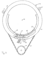
- the holding device 30 shown in FIG. 4 is for holding one electrically operated device can be used to influence of light from a headlight with the headlight is connectable.
- the octagonal ring 48 on Light emission of the headlamp attached that he the one Light has a dimming effect all around.
- the octagonal Ring 48 is part of the fastener 31 or is with the fastener 31 when mounting the holding device 30 connectable.
- Four eight are shown uniformly in FIG Screw connections distributed over the octagonal ring 48 49 to an annular plate of the fastener 31.
- the electrically operated part can in particular be a Anti-dazzle flap that is driven by an electric motor or can be closed.
- the electrically powered part is connected to the rotating ring 32.
- the rotating ring 32 encloses one in a central potential Light propagation direction 28 rotating axis 20 all around in Distance. It is about the axis of rotation 20 relative to the fastener 31 rotatably mounted.
- the holding device has 30 an annular ring (not shown) between the fastening element 31 and the rotary ring 32 arranged rotary bearing, preferably a ball bearing.
- a rotary movement can, for example, that described with reference to FIGS. 1 and 3 Drive arrangement can be used.
- a flat cable 39 supply cable from a connector 43 on the outer periphery of the fastener 31 along via a cable deflection roller 33 on which the flat cable 39 is deflected approximately in the reverse direction up to electrically operated part of the facility.
- the flat cable 39 ends at a rotary stop 47 in the right half of the picture.
- Strain relief for the flat cable 39 may be attached.
- the flat cable 39 fixed relative in another way to the rotating element 32 or to the electrically operated part to position the facility.
- the third cable section 42 is under tension in a continuous range of rotational positions.
- the tensile stress is applied by a transmission element 36 formed from a pull cord 37 and a helical spring 38.
- the third cable section 42 also exerts a tensile force on the transmission element 36 which causes a tension of the transmission element 36.
- the transmission element 36 is connected at its first end to the outer circumference of the fastening element 31. At its second end 45, it is connected to a rotary stop 47 which can be seen in FIGS. 4 and 5 in the left half of the figure.
- the helical spring 38 connects the rotary stop 47 to the end of the pull cord 37.
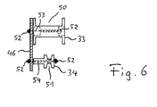
- the cable deflection roller 33 has a central, axial bore or recess in which a shaft 53 is arranged.
- the shaft 53 is at its ends each provided with an external thread, one on each Nut 52 is screwed on. One end protrudes a hole in a connecting plate 46 through to the side of the connecting plate facing away from the cable deflection roller 33 46.
- the drawstring pulley 34 connected to the connecting plate 46.
- the cable deflection roller 33 has an approximately in profile rectangular groove 50 for receiving the flat cable 39.
- the Drawstring pulley 34 has a conical profile tapering groove 51 for receiving the pull cord 37.
- the groove-like tread 35 only a shallow groove profile depth, d. H. the supernatant of the two Walls laterally on the tread 35 in the radial direction to the outside is small.
- the device according to the invention in particular by the is particularly preferred embodiment described above reliable routing of a supply cable within of a defined spatial area over a continuous range of rotational positions of the device guaranteed. Due to the special construction of the Holding device of the device is handling, especially the assembly and maintenance, compared to the facility already known facilities simplified.
Landscapes
- Engineering & Computer Science (AREA)
- General Engineering & Computer Science (AREA)
- Physics & Mathematics (AREA)
- Spectroscopy & Molecular Physics (AREA)
- Lighting Device Outwards From Vehicle And Optical Signal (AREA)
- Non-Portable Lighting Devices Or Systems Thereof (AREA)
- Circuit Arrangements For Discharge Lamps (AREA)
- Storing, Repeated Paying-Out, And Re-Storing Of Elongated Articles (AREA)
Claims (18)
- Installation fonctionnant à l'électricité, en particulier installation entraínée par un moteur électrique, telle que changeur de couleur, volet de réduction de lumière, store à lumière, ou similaire, pour exercer une influence sur une lumière sortant d'un projecteur, en particulier d'un projecteur de scène, avec un dispositif de maintien (10, 30) qui peut être relié avec le projecteur par l'intermédiaire d'un élément de fixation, en particulier en forme d'anneau, (31) pour maintenir l'installation et qui comprend un élément tournant, en particulier en forme d'anneau, (11, 12, 32), lequel peut tourner, en étant en particulier entraíné en rotation, par rapport à l'élément de fixation (31) autour d'un axe de rotation (20) s'étendant dans une direction potentielle d'extension de la lumière (28), alors que l'élément de fixation (31) et/ou l'élément tournant (11, 12, 32) s'étendent au moins partiellement avec un espacement autour de l'axe de rotation (20), caractérisée en ce qu'un câble électrique d'alimentation (19, 39) pour l'installation, qui est positionné ou qui peut être positionné sur une première section de câble (22, 40) de manière fixe par rapport à l'élément de fixation (31) et sur une deuxième section de câble (23, 41) de manière fixe par rapport à l'élément tournant (11, 12, 32), se trouve dans une troisième section de câble (42) s'étendant à peu près en direction périphérique et réalise entre la première section de câble (22, 40) et la deuxième section de câble (23, 41) un renvoi tel dans la direction opposée en formant une boucle de renvoi (24) qu'avec la rotation du dispositif de maintien (10, 30) la position de la boucle de renvoi par rapport à la première section de câble (22, 40) et à la deuxième section de câble (23, 41) change.
- Installation selon la revendication 1, caractérisée en ce que le câble d'alimentation (19) est configuré comme câble plat et s'étend dans la troisième section de câble, le côté plat étant à peu près parallèle à l'axe de rotation (20) du dispositif de maintien (10).
- Installation selon la revendication 1 ou 2, caractérisée en ce que le câble d'alimentation (19) s'étend à l'intérieur d'un canal périphérique (21) formé entre le dispositif de maintien (10) et le projecteur de scène.
- Installation selon la revendication 3, caractérisée en ce que le dispositif de maintien (10) comprend une bague de montage (11) ainsi qu'une platine de montage qui est fixée sur celle-ci et qui comprend une ouverture centrale de passage (18) pour la sortie de la lumière.
- Installation selon l'une quelconque des revendications 1 à 4, caractérisée en ce qu'un palier tournant entre le projecteur de scène et le dispositif de maintien (10) est formé d'une part par un cerceau (12) disposé sur le dispositif de maintien (10) et d'autre part par au moins trois rouleaux de palier (15) disposés sur le projecteur de scène en association avec le cerceau (12) et répartis uniformément sur la périphérie de celui-ci en circulant sur lui, ou inversement.
- Installation selon la revendication 5, caractérisée en ce que le cerceau (12) disposé sur le dispositif de maintien (10) est configuré sur le côté dirigé dans le sens radial vers l'extérieur comme profilé en E, alors que l'une des rainures périphériques (13) sert à recevoir les au moins trois rouleaux de palier (15) et que l'autre rainure périphérique (14) sert à recevoir une chaíne d'entraínement (16) ou une courroie d'entraínement qui est. couplée avec un pignon (17) ou avec une poulie d'entraínement d'un moteur électrique monté sur le projecteur de scène, en particulier un moteur pas à pas ou un motoréducteur.
- Installation selon la revendication 5 ou 6, caractérisée en ce que le cerceau (12) disposé sur le dispositif de maintien (10) est configuré sur le côté radial intérieur comme profilé en L qui, en état de montage du dispositif de maintien (10), délimite avec un profilé en L (26) monté en sens inverse sur le projecteur de scène autour de sa sortie de lumière le canal périphérique (21) servant à recevoir le câble d'alimentation (19).
- Installation selon la revendication 7, caractérisée en ce que le profilé en L (26) qui s'étend sur le projecteur de scène autour de la sortie de lumière est une section de profilé s'étendant sur un angle périphérique qui correspond à l'angle de rotation maximal du dispositif de maintien (10), en particulier sur un angle d'au moins 180° à environ 270°, de sorte qu'un canal périphérique (21) d'une longueur correspondante, sensiblement fermé vers tous les côtés et servant à recevoir du câble d'alimentation (19) est défini, c'est-à-dire de telle façon que la boucle de renvoi (24) du câble d'alimentation (19) puisse, à l'intérieur du canal périphérique (21), suivre sans contraintes le mouvement de rotation du dispositif de maintien (10).
- Installation selon l'une quelconque des revendications 1 à 8, caractérisée en ce que la troisième section de câble (42) fait l'objet d'un renvoi ou peut faire l'objet d'un renvoi par exemple dans la direction de renvoi au moyen d'un élément de renvoi (33) en formant la boucle de renvoi et en ce que l'élément de renvoi (33) peut être déplacé de telle façon le long d'un guide (35) sur un pourtour extérieur de l'élément tournant (32) et/ou de l'élément de fixation (31) que la troisième section de câble (42) soit soumise à une contrainte de traction dans une zone continue de positions de rotation.
- Installation selon la revendication 9, caractérisée en ce que le dispositif de maintien (30) comprend un élément de transmission oblong (36), pouvant être plié de manière réversible au moins dans une section et servant à transmettre une force de traction sur la troisième section de câble (42), en ce que l'élément de fixation (32) est relié avec une première extrémité (44) de l'élément de transmission (36) et en ce que l'élément de transmission (36) s'étend par exemple en direction du pourtour, fait l'objet d'un renvoi par exemple dans le sens inverse à l'aide d'un élément de renvoi (34) pouvant être déplacé le long du guide (35) et est relié à une deuxième extrémité (45) avec l'élément tournant (32).
- Installation selon la revendication 10, caractérisée en ce que l'élément de transmission (36) comprend un élément souple de traction (38) pour appliquer la tension de traction.
- Installation selon la revendication 11, caractérisée en ce que l'élément de traction (38) est un ressort hélicoïdal.
- Installation selon l'une quelconque des revendications 10 à 12, caractérisée en ce que l'élément tournant (32) comprend une butée de rotation (47) avec laquelle est reliée la deuxième extrémité (45) de l'élément de transmission (36).
- Installation selon l'une quelconque des revendications 10 à 13, caractérisée en ce que l'élément de renvoi (33) selon la revendication 9 est un premier élément de renvoi, en ce que l'élément de renvoi (34) selon la revendication 10 est un deuxième élément de renvoi et en ce que les deux éléments de renvoi (33 ; 34) sont disposés l'un derrière l'autre dans le sens périphérique et dans une position fixe l'un par rapport à l'autre.
- Installation selon l'une quelconque des revendications 9 à 14, caractérisée en ce que l'élément de renvoi (33) selon la revendication 9 ou au moins un des éléments de renvoi (33 ; 34) selon la revendication 14 est un rouleau de renvoi avec une rainure (50 ; 51) pour le guidage du câble d'alimentation (39) ou de l'élément de transmission (36).
- Installation selon la revendication 15, caractérisée en ce que l'au moins un rouleau de renvoi est logé de manière tournante telle, de préférence sur un arbre (53 ; 54), qu'il roule sur le guide (35) lors de la rotation de l'élément tournant (32).
- Installation selon l'une quelconque des revendications 9 à 16, caractérisée en ce que l'élément tournant (32) comprend sur son pourtour extérieur une surface de roulement s'étendant en direction du pourtour et disposant de parois latérales à la manière d'une rainure, laquelle surface de roulement constitue le guide (35) pour l'élément de renvoi ou pour les éléments de renvoi (33 ; 34).
- Installation selon la revendication 17, caractérisée en ce que le câble d'alimentation (39) est configuré comme câble plat qui est disposé ou qui peut être disposé de telle façon que, dans la troisième section de câble (42), un côté plat s'étend à peu près le long de la surface de roulement.
Applications Claiming Priority (4)
| Application Number | Priority Date | Filing Date | Title |
|---|---|---|---|
| DE29705129U | 1997-03-20 | ||
| DE29705129U DE29705129U1 (de) | 1997-03-20 | 1997-03-20 | Beleuchtungseinrichtung |
| DE29713757U DE29713757U1 (de) | 1997-08-01 | 1997-08-01 | Elektrisch betriebene Einrichtung für Scheinwerfer |
| DE29713757U | 1997-08-01 |
Publications (3)
| Publication Number | Publication Date |
|---|---|
| EP0866262A2 EP0866262A2 (fr) | 1998-09-23 |
| EP0866262A3 EP0866262A3 (fr) | 2000-11-02 |
| EP0866262B1 true EP0866262B1 (fr) | 2004-10-06 |
Family
ID=26060099
Family Applications (1)
| Application Number | Title | Priority Date | Filing Date |
|---|---|---|---|
| EP98105133A Expired - Lifetime EP0866262B1 (fr) | 1997-03-20 | 1998-03-20 | Installation fonctionnant à l'électricité pour projecteur |
Country Status (4)
| Country | Link |
|---|---|
| EP (1) | EP0866262B1 (fr) |
| AT (1) | ATE278907T1 (fr) |
| DE (1) | DE59812055D1 (fr) |
| ES (1) | ES2230632T3 (fr) |
Family Cites Families (3)
| Publication number | Priority date | Publication date | Assignee | Title |
|---|---|---|---|---|
| DE8519583U1 (de) * | 1985-07-12 | 1986-11-27 | Quartzcolor Ianiro S.p.A., Rom/Roma | Fernsteuerbare Beleuchtungseinrichtung, insbesondere für Theater, Photo-, Film- und Fernsehstudios u. dgl. |
| US4729071A (en) * | 1986-11-03 | 1988-03-01 | Altman Stage Lighting Co. | Low-inertial beam direction lighting system |
| GB2270969A (en) * | 1992-09-29 | 1994-03-30 | Strand Lighting Ltd | Luminaire closure assembly |
-
1998
- 1998-03-20 AT AT98105133T patent/ATE278907T1/de active
- 1998-03-20 ES ES98105133T patent/ES2230632T3/es not_active Expired - Lifetime
- 1998-03-20 DE DE59812055T patent/DE59812055D1/de not_active Expired - Lifetime
- 1998-03-20 EP EP98105133A patent/EP0866262B1/fr not_active Expired - Lifetime
Also Published As
| Publication number | Publication date |
|---|---|
| DE59812055D1 (de) | 2004-11-11 |
| ATE278907T1 (de) | 2004-10-15 |
| EP0866262A3 (fr) | 2000-11-02 |
| EP0866262A2 (fr) | 1998-09-23 |
| ES2230632T3 (es) | 2005-05-01 |
Similar Documents
| Publication | Publication Date | Title |
|---|---|---|
| EP0338362B1 (fr) | Dispositif de protection solaire | |
| DE69735102T2 (de) | Tragebandwickelvorrichtung für fensterabdeckung | |
| EP4015848B1 (fr) | Dispositif d'entraînement par câble d'un véhicule automobile | |
| DE602004001992T2 (de) | Getriebe mit schraube, mutter und seil | |
| DE60210207T2 (de) | Vorrichtung für das automatische Bewegen eines Vorhanges entlang einer Vorhangschiene | |
| DE69508549T2 (de) | Wickelvorrichtung für Tragebänder von Jalousien | |
| DE2056725C3 (de) | Elektromechanische Zugvorrichtung zu schienengeführten Gehängen | |
| AT399370B (de) | Jalousie | |
| EP0313809A1 (fr) | Volet roulant pour fenêtre de toiture | |
| DE2831870A1 (de) | Universal-seilzugfensterheber | |
| AT394880B (de) | Rafflamellenstore | |
| DE3415551C2 (de) | Rolladen für Dachfenster | |
| DE69703620T2 (de) | Elastische mittel zum aufrollen eines rollvorhangs | |
| DE2853763A1 (de) | Vertikaljalousie mit um ihre lotrechte achse schwenkbaren sowie seitlich verschiebbaren lamellen | |
| WO2001018346A1 (fr) | Store en lamelles | |
| DE3731374C2 (fr) | ||
| EP0684361B1 (fr) | Dispositif de levage et de pivotement pour stores à lamelles | |
| EP0866262A2 (fr) | Installation fonctionnant à l'électricité pour projecteur | |
| DE19930785B4 (de) | Rolladen, insbesondere Trapezrolladen | |
| EP0377844B1 (fr) | Dispositif de levage d'un store | |
| DE19645230C2 (de) | Gurtführungsvorrichtung | |
| DE4327230C1 (de) | Rolladen für Dachfenster | |
| DE29713757U1 (de) | Elektrisch betriebene Einrichtung für Scheinwerfer | |
| EP0651123A1 (fr) | Ensemble de connection pour le raccordement d'un arbre d'entraînement d'un panneau de porte à différents ensembles d'entraînement motorisés | |
| DE3210793A1 (de) | Vorrichtung zum aufwickeln eines kabels |
Legal Events
| Date | Code | Title | Description |
|---|---|---|---|
| PUAI | Public reference made under article 153(3) epc to a published international application that has entered the european phase |
Free format text: ORIGINAL CODE: 0009012 |
|
| AK | Designated contracting states |
Kind code of ref document: A2 Designated state(s): AT DE ES FR GB IT |
|
| AX | Request for extension of the european patent |
Free format text: AL;LT;LV;MK;RO;SI |
|
| PUAL | Search report despatched |
Free format text: ORIGINAL CODE: 0009013 |
|
| AK | Designated contracting states |
Kind code of ref document: A3 Designated state(s): AT BE CH DE DK ES FI FR GB GR IE IT LI LU MC NL PT SE |
|
| AX | Request for extension of the european patent |
Free format text: AL;LT;LV;MK;RO;SI |
|
| 17P | Request for examination filed |
Effective date: 20001208 |
|
| AKX | Designation fees paid |
Free format text: AT DE ES FR GB IT |
|
| GRAP | Despatch of communication of intention to grant a patent |
Free format text: ORIGINAL CODE: EPIDOSNIGR1 |
|
| GRAS | Grant fee paid |
Free format text: ORIGINAL CODE: EPIDOSNIGR3 |
|
| GRAA | (expected) grant |
Free format text: ORIGINAL CODE: 0009210 |
|
| RIC1 | Information provided on ipc code assigned before grant |
Ipc: 7F 21V 21/30 B Ipc: 7F 21S 8/00 A |
|
| AK | Designated contracting states |
Kind code of ref document: B1 Designated state(s): AT DE ES FR GB IT |
|
| REG | Reference to a national code |
Ref country code: GB Ref legal event code: FG4D Free format text: NOT ENGLISH |
|
| REF | Corresponds to: |
Ref document number: 59812055 Country of ref document: DE Date of ref document: 20041111 Kind code of ref document: P |
|
| GBT | Gb: translation of ep patent filed (gb section 77(6)(a)/1977) |
Effective date: 20050201 |
|
| REG | Reference to a national code |
Ref country code: ES Ref legal event code: FG2A Ref document number: 2230632 Country of ref document: ES Kind code of ref document: T3 |
|
| PLBE | No opposition filed within time limit |
Free format text: ORIGINAL CODE: 0009261 |
|
| STAA | Information on the status of an ep patent application or granted ep patent |
Free format text: STATUS: NO OPPOSITION FILED WITHIN TIME LIMIT |
|
| ET | Fr: translation filed | ||
| 26N | No opposition filed |
Effective date: 20050707 |
|
| PGFP | Annual fee paid to national office [announced via postgrant information from national office to epo] |
Ref country code: ES Payment date: 20070308 Year of fee payment: 10 |
|
| REG | Reference to a national code |
Ref country code: ES Ref legal event code: FD2A Effective date: 20080322 |
|
| PG25 | Lapsed in a contracting state [announced via postgrant information from national office to epo] |
Ref country code: ES Free format text: LAPSE BECAUSE OF NON-PAYMENT OF DUE FEES Effective date: 20080322 |
|
| REG | Reference to a national code |
Ref country code: FR Ref legal event code: PLFP Year of fee payment: 19 |
|
| PG25 | Lapsed in a contracting state [announced via postgrant information from national office to epo] |
Ref country code: IT Free format text: LAPSE BECAUSE OF NON-PAYMENT OF DUE FEES Effective date: 20160320 |
|
| REG | Reference to a national code |
Ref country code: FR Ref legal event code: PLFP Year of fee payment: 20 |
|
| PGFP | Annual fee paid to national office [announced via postgrant information from national office to epo] |
Ref country code: FR Payment date: 20170327 Year of fee payment: 20 |
|
| PGFP | Annual fee paid to national office [announced via postgrant information from national office to epo] |
Ref country code: AT Payment date: 20170328 Year of fee payment: 20 Ref country code: GB Payment date: 20170328 Year of fee payment: 20 |
|
| PGFP | Annual fee paid to national office [announced via postgrant information from national office to epo] |
Ref country code: DE Payment date: 20170330 Year of fee payment: 20 |
|
| PG25 | Lapsed in a contracting state [announced via postgrant information from national office to epo] |
Ref country code: IT Free format text: LAPSE BECAUSE OF NON-PAYMENT OF DUE FEES Effective date: 20160320 |
|
| PGFP | Annual fee paid to national office [announced via postgrant information from national office to epo] |
Ref country code: IT Payment date: 20170323 Year of fee payment: 20 |
|
| PGRI | Patent reinstated in contracting state [announced from national office to epo] |
Ref country code: IT Effective date: 20170710 |
|
| REG | Reference to a national code |
Ref country code: DE Ref legal event code: R071 Ref document number: 59812055 Country of ref document: DE |
|
| REG | Reference to a national code |
Ref country code: GB Ref legal event code: PE20 Expiry date: 20180319 |
|
| PG25 | Lapsed in a contracting state [announced via postgrant information from national office to epo] |
Ref country code: GB Free format text: LAPSE BECAUSE OF EXPIRATION OF PROTECTION Effective date: 20180319 |
|
| REG | Reference to a national code |
Ref country code: AT Ref legal event code: MK07 Ref document number: 278907 Country of ref document: AT Kind code of ref document: T Effective date: 20180320 |